 Open Access Article
Enhanced charge transport properties of an LFP/C/graphite composite as a cathode material for aqueous rechargeable lithium batteries†
Wenyuan Duan a,
Mubashir Husain
 b,
Yanlin Li
 *c,
Najeeb ur Rehman Lashari*de,
Yuhuan Yanga,
Cheng Maa,
Yuzhen Zhao
 a and
Xiaorui Lif
aXi'an Key Laboratory of Advanced Photo-electronics Materials and Energy Conversion Device, Xijing University, Xi'an 710123, China
bMaterials Research Laboratory, Department of Physics, Faculty of Sciences (FOS), International Islamic University (IIU), H-10, Islamabad 44000, Pakistan
cSchool of Materials Science and Engineering, Xi'an University of Architecture & Technology, Xi'an 710055, China. E-mail: liyanlin@xauat.edu.cn
dInstitute for Advanced Study, Shenzhen University, Shenzhen, 518060, China. E-mail: najeeblashari@xpu.edu.cn
eDepartment of Chemistry and Physics, Jackson State University, USA
fSchool of Environmental and Chemical Engineering, Jiangsu University of Science and Technology, Zhenjiang, 212114, P. R. China
First published on 23rd August 2023
Abstract
Electrodes that offer quick ion transport, a large surface area, and excellent electrical conductivity support high performance aqueous rechargeable lithium batteries. LiFePO4 (LFP) nanoparticles have been successfully coated with carbon by a chemical sol–gel route, and assembled on graphite by an ultrasonication method to acquire LFP/C/graphite. This LFP/C/graphite composite exhibits exceptional electrochemical performance at various current densities (1C to 20C). LFP/C/graphite delivers better capacity that is higher than that of LFP/C particles and high stability after 60 cycles at a current density of 1C for aqueous rechargeable lithium batteries as a cathode material. The graphite serves as a good volume buffer in improving the lithium performance of LFP/C/graphite during the charge/discharge process. The LFP/C/graphite composite shows high rate capability at 20C that returned to the initial capacity at 1C after 25 cycles with coulombic efficiency of 97%. Therefore, this effort presents a super low-cost route to fabricate high performance cathode materials in aqueous rechargeable lithium batteries and other energy storage appliances.
Introduction
Rechargeable lithium-ion batteries are extensively used in modern electronics and are fast growing in the field of hybrid electric vehicles and electric cars. However, in order to make their use more viable for large scale applications like hybrid electric cars and vehicles, these must be substantially more efficient, and several basic difficulties associated with them must be eliminated.1–4 The use of organic electrolytes raises concerns about environmental deterioration and expense. The most critical concern that must be addressed right away is the safety. Due to the fact that lithium-ion batteries are commonly built with organic electrolyte, they cannot meet high power instruments owing to safety concerns caused by volatile and combustible organic electrolytes as well as the issues associated with the flammable electrolytes, such as stringent fabrication and packaging cost. As a result, it is critical to investigate novel energy storage technologies in order to increase their safety.5–7 Dahn et al. proposed the first aqueous rechargeable lithium battery that consists of an anode (VO2) and a cathode (LiMn2O4) in a 5 M LiNO3 aqueous electrolyte.8 An aqueous rechargeable lithium battery provides various potential advantages over typical lithium-ion batteries including higher safety and reduced cost with organic electrolytes. Additionally, aqueous electrolytes have far superior ionic conductivity than organic electrolytes, hence, allowing the aqueous rechargeable lithium batteries to be used at a higher cycle rate with lesser electrolyte resistance. Since the last two decades due to a limited stable operating voltage range, aqueous rechargeable lithium batteries' low energy density has stifled their expansion.9,10 The limited electrochemical stability window renders the aqueous rechargeable lithium battery less tolerant to overcharging.Aside from the ionic conductivity of electrode materials, recent research on aqueous rechargeable lithium batteries has concentrated on expanding the stable working voltage window, enhancing cycle performance, and increasing working voltage.11–14 There are several techniques that researchers have been used to boost performance. The simplest and most targeted technique is to make changes to the cathode of the battery. The discovery of high-performance cathode materials for lithium-ion batteries has piqued the interest of researchers all around the world. As a result, the electrochemical characteristics and processes of cathode materials have received a lot of attentions during the last decade.15–17 The cathode materials such as LiFePO4, LiMn2O4, and LiCoO2 were employed for the aqueous rechargeable lithium batteries.18–20 Lithium iron phosphate (LiFePO4) has a high theoretical specific capacity of 170 mA h g−1, is structurally stable, and exhibits chemical resistance, making it an ideal cathode material for large lithium batteries. Additionally, non-toxic LiFePO4 removes the cost restrictions of a cathode that contains cobalt, which is a significant advantage for large-scale applications.21 TiS2/LiFePO4 complete cells were systematically optimized in order to produce highly efficient aqueous rechargeable lithium-ion batteries. The overall electrochemical performance of the cell was examined in relation to the working potential window, the concentration of tri-methyl-silyl-borate salt, and the current collectors. A cell operated under ideal circumstances generated a steady 41 W h kg−1 energy density having excellent coulombic efficiency of about 99% and after 100 cycles, 70% capacity was retained.22 Ultra-thick LiFePO4 electrodes with millimeter-scale were prepared with varying concentrations of Li2SO4 to adjust the conductivity of the aqueous electrolyte. The improved electrolyte conductivity optimized electrochemical behavior by delivering strong lithium-ion flux even in 2.0 mm ultra-thick LiFePO4 electrodes with a capacity of 52 mA h cm−2. The functioning of mm-thick ultra-thick LiFePO4 electrodes in a handmade three-electrode cell demonstrated better cycle performance and rate capability not possible with organic electrolytes.23 Wang et al. found that employing LiNi0.5Mn1.5O4 as the cathode led to 126 W h kg−1 energy density and high discharge voltage in aqueous rechargeable lithium batteries.24
For many cathode materials, the core issue is lack of adequate electron transport channels which results in significant loss of energy during charge/discharge cycles at high cycling rates. This issue can be solved by incorporating conductive nano-additives such as graphite into active materials to produce composite structures. The electrophoresis was employed to fabricate battery cathodes constructed of LiFePO4/EGO composites having fiber-reinforcements. The greatest performances were 72 and 131 mA h g−1 at 2C and 0.1C, respectively with a retention of 55.4% of starting capacity. The electrodes made up of LiFePO4/EGO composites were used as a cathode in construction of a full cell. With exceptional long-lasting cycling stability of over 88% for 300 cycles, it demonstrated maximum specific energy (222.1 W h kg−1) and specific power (290.9 W kg−1). This indicates that these LiFePO4/EGO composites are offering great promise to be used as the cathode material for highly effective lithium-ion batteries.21 The hydrothermal process was used to effectively produce a 3D porous LiFePO4/graphene composite aerogel and the sample with 10% graphene confirmed high discharge capacity (168 mA h g−1), high (96%) retention and superlative electrochemical performance for 800 cycles.25 Hydrothermal technique was used to manufacture the self-assembled LiFePO4/graphene composites. The composite LiFePO4/graphene has a high discharge capacity of 145.8 mA h g−1 at 0.2C, which is much higher than LiFePO4. Furthermore, LiFePO/graphene has significantly higher rate capability and great cyclability.26
In current research work, we presented a super low-cost method to synthesize LiFePO4/C/graphite (LFP/C/graphite) composites by using commercial graphite with ultra-low selling price. Carbon-graphite emulsion can improve cathode material ionic conductivity and avoid LFP particle agglomeration. The acquired LFP/C/graphite composite demonstrates high reversible capacity and excellent cycling performance as a cathode material in aqueous rechargeable lithium batteries.
Experimental
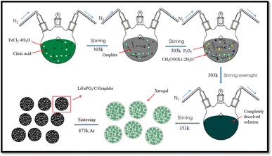
The chemical sol–gel method is used to synthesize LFP/C particles using FeCl2·4H2O, P2O5, CH3COOLi·2H2O and critic acid with a molar ratio of 10![[thin space (1/6-em)]](https://www.rsc.org/images/entities/char_2009.gif) :
:![[thin space (1/6-em)]](https://www.rsc.org/images/entities/char_2009.gif) 10
10![[thin space (1/6-em)]](https://www.rsc.org/images/entities/char_2009.gif) :
:![[thin space (1/6-em)]](https://www.rsc.org/images/entities/char_2009.gif) 5
5![[thin space (1/6-em)]](https://www.rsc.org/images/entities/char_2009.gif) :
:![[thin space (1/6-em)]](https://www.rsc.org/images/entities/char_2009.gif) 5. Continues magnetic stirring is used to liquefy the 4 wt% graphite in 50 mL ethanol solution at 303 K. Then, the solution is stirred overnight under nitrogen gas environment until it completely dissolved and placed for heating at 353 K to acquire xerogel as shown in Fig. 1. Afterwards, the xerogel is sintered for 06 hours at 873 K temperature in argon gas atmosphere to achieve well organized LFP/C/G composites as displayed in Fig. 1.
5. Continues magnetic stirring is used to liquefy the 4 wt% graphite in 50 mL ethanol solution at 303 K. Then, the solution is stirred overnight under nitrogen gas environment until it completely dissolved and placed for heating at 353 K to acquire xerogel as shown in Fig. 1. Afterwards, the xerogel is sintered for 06 hours at 873 K temperature in argon gas atmosphere to achieve well organized LFP/C/G composites as displayed in Fig. 1.
Three electrode system including the working electrode, counter electrode, and reference electrode is utilized to assemble and analyze the electrochemical performance. The electrolyte is prepared with magnetic stirring for 30 min by dissolving ZnSO4·7H2O in a saturated LiNO3 solution and adding drop by drop saturated LiOH·H2O solution until pH 4. For electrochemical analysis, the cathode is LFP/C/graphite (working electrode), the reference electrode is saturated calomel electrode, and the counter electrode is zinc (anode). The working electrode is configured with 12 mg active material weight, 0.2 mm in thickness, 15 mm in length, and 5 mm in width. With the help of n-methylpyrrolidone solvent, the working electrode is fabricated with a ratio of 10![[thin space (1/6-em)]](https://www.rsc.org/images/entities/char_2009.gif) :
:![[thin space (1/6-em)]](https://www.rsc.org/images/entities/char_2009.gif) 80
80![[thin space (1/6-em)]](https://www.rsc.org/images/entities/char_2009.gif) :
:![[thin space (1/6-em)]](https://www.rsc.org/images/entities/char_2009.gif) 10 of acetylene black, LFP/C/graphite (active material), and polyvinylidene fluoride, respectively. The attained slurry is homogeneously mixed through ultra-sonication for 5 minutes. The slurry is then coated on nickel mesh and dried for 10 hours at a temperature of 373 K in furnace under vacuum. Also, the zinc sheet is mixed in ethanol under vacuum for 02 hours at 323 K using ultra-sonicator. For the electrochemical testing, the experimental de-oxygenated electrolyte is prepared thru spangling high purity nitrogen for 02 and 03 hours.
10 of acetylene black, LFP/C/graphite (active material), and polyvinylidene fluoride, respectively. The attained slurry is homogeneously mixed through ultra-sonication for 5 minutes. The slurry is then coated on nickel mesh and dried for 10 hours at a temperature of 373 K in furnace under vacuum. Also, the zinc sheet is mixed in ethanol under vacuum for 02 hours at 323 K using ultra-sonicator. For the electrochemical testing, the experimental de-oxygenated electrolyte is prepared thru spangling high purity nitrogen for 02 and 03 hours.
The XRD investigations of LFP/C and LFP/C/graphite composites are performed using a Bruker D8-Advanced XRD diffractometer. The morphology of LFP/C and LFP/C/graphite is visualized through SEM, Model JEOL JEM-2100, and TEM, Model JEOL JEM-7000F, Japan. To monitor the Raman spectroscopy of LFP/C and LFP/C/graphite composites in the spectral range of 100 cm−1 to 4000 cm−1, a laser confocal micro RAMAN spectrometer with three lasers was used. The thermal behavior of LFP/C and LFP/C/graphite composites were investigated on a thermogravimetry (TG) using a Labsys Evo 1600 °C, SETARAM Instrumentation, Caluire. An Ametek VMC-4 system is used to perform cyclic voltammetry (CV) measurements in aqueous electrolyte from −0.6 V to 1.2 V at 2 mV s−1. The Arbin BT2000 instrument is utilized to achieve the galvanostatic charge/discharge tests.
Results and discussion
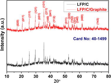
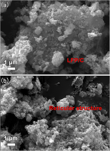
X-rays diffraction (XRD) is used to investigate the crystal structure of LFP/C and LFP/C/graphite composites as given in Fig. 2. The XRD spectra of LFP/C and LFP/C/graphite composites possesses main (020), (011), (111), (121), (131), (222) and (400) diffraction peaks at 17.1°, 20.7°, 25.5°, 29.7°, 35.4°, 52.5° and 61.7° diffraction angles. The indexed diffraction peaks exactly matched with JCPDS-ICDD card No. 40-1499 that reflect crystalline orthorhombic olivine structure. No peak shift is observed in the XRD spectra of LFP/C/graphite composites which indicates that graphite did not alter the structure of LFP/C due to its intrinsic nature.The scanning electron microscopy (SEM) is utilized to investigate the morphology and size of the synthesized material. Fig. 3 displays the SEM images of the composites made of LFP/C and LFP/C/graphite, respectively. The nano-micron particles are clearly visible in the SEM images of LFP/C nanoparticles (Fig. 3a), while a uniform morphology is observed with the addition of graphite on the LFP/C nanoparticles (Fig. 3b). This structure provides pathways for lithium ions for intercalation/de-intercalation as well as adequate contact between the aqueous electrolyte and the electrode. In Fig. 4, TEM images are used to further explore the morphology of LFP/C and LFP/C/graphite composites. The synthesized LFP nanoparticles explicit a uniform morphology with carbon Fig. 4a. It can be seen from Fig. 4b that LFP/C/graphite composite consist of several small crystallites. The presence of carbon suggests that LFP particles are firmly combined with graphite. Moreover, the connections between the carbon coated LFP particles and graphite is clearly evident from Fig. 4b. Combined with Fig. 3 and 4, it can be seen that the surface of LFP/C nanoparticles is uniformly coated with a flocculent carbon layer, and on this basis, a more three-dimensional network structure is formed on the surface of LFP/C/graphite nanoparticles by the addition of graphite. All of these factors contribute to improved electrochemical performance of electrode materials. Furthermore, the clearer structure of LFP and flocculent carbon, as well as graphite, could be obtained from HRTEM in Fig. 4c and d.
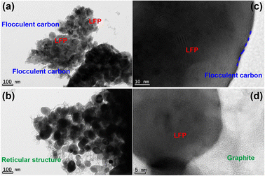 | ||
| Fig. 4 TEM micrographs of (a) LFP/C and (b) LFP/C/graphite composites, HRTEM micrographs of (c) LFP/C and (d) LFP/C/graphite composites. | ||
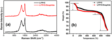
Fig. 5 investigates the structural and compositional characteristics of LFP/C and LFPO/C/graphite composites using Raman spectroscopy and thermogravimetry (TG). Fig. 5a depicts the Raman spectroscopy of LFP/C and LFP/C/graphite composites that shows the Raman shift of the composites. The oxygen atoms at the tetragonal positions are prone to the symmetric stretching (A1g mode) along tetrahedral bonds. The bands appeared in Raman spectra confirmed the structure of LFP nanoparticles. In Fig. 5a, the vibrations of the planar sp2-carbon atoms is denoted by E2g symmetry (G-band), and began around 1548 cm−1. In the Raman spectra, the peak around 1330 cm−1 reflected the j-point phonons of A1g symmetry (D-band) corresponds the aggregations or defect levels that arises inside the covers of graphite in LFP/C/graphite composites. The breakage of sp2 bonds to form further sp3 bonds is connected with the strong D-band in LFP/C/graphite composites. Fig. 5b shows the TG curves of LFP/C and LFPO/C/graphite composites. The TG curves reveal that the total mass loss during the entire heating process of the sample from room temperature to 1000 °C. The mass loss process occurred and continuous from 60 °C to 200 °C. The mass loss process from 60 °C to 200 °C is due to evaporation of water molecules of LFP/C and LFP/C/graphite electrodes. From around 200 °C to 700 °C, no thermal or steep mass loss process can be observed. The mass loss process occurred quickly from 700 °C to 1000 °C that corresponds to the pyrolysis of LFP and C. Thus, it can be assumed that LFP/C and LFP/C/graphite composites exhibited crystalline phase are thermally stable.
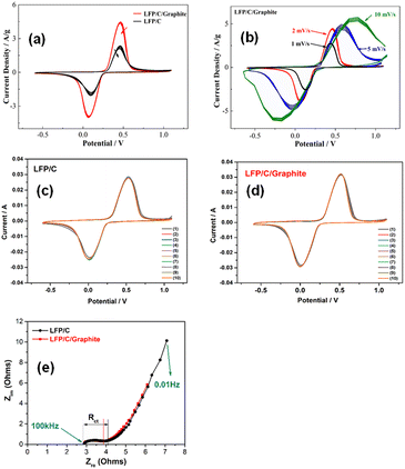
The cyclic voltammetry “CV” curves of the LFP/C and LFP/C/graphite electrodes for 10 cycles at a scan rate of 2 mV s−1 are shown in Fig. 6a. The electrodes' CV curves in an aqueous electrolyte of LiNO3/ZnSO4 are measured between 0.6 and 1.2 V. The anodic peaks for LFP/C and LFP/C/graphite electrodes are at 0.70 V and 0.75 V, respectively, and the cathodic peaks are at −0.18 V and −0.23 V, respectively. The reversible extraction/insertion of lithium ions from the LFP/C electrode to the LFP/C/graphite electrode is represented by these cathodic/anodic peaks. The cathodic/anodic peaks of LFP/C/graphite electrode did not show any change in position after 10 cycles which is due to good reversibility for lithium ions extraction/insertion. Furthermore, LFP/C/graphite electrode current density peaks are greater than LFP/C electrode at 0.70 V as presented in Fig. 6(a). This may be due to the fact that aqueous rechargeable lithium batteries with LFP/C/graphite electrode can provide high discharge/charge capacity. The CV curves of LFP/C/graphite electrode at different scan rates (i.e. 1 mV s−1, 2 mV s−1, 5 mV s−1, and 10 mV s−1) are shown in Fig. 6b. It is evident from Fig. 6b that the current density increases gradually with the increase of the scan rate of LFP/C/G electrode. The extraordinary stability in the contours of the CV curves of the LFP/C/graphite electrode at various scan rates indicates superior charge storage capacity of working electrode. The intercalation/de-intercalation reversibility of lithium ions can be determined using the area under CV curves. When compared to LFP/C electrodes, the area under the CV curves for LFP/C/graphite electrodes increases, indicating that the maximal electrode active surfaces are reachable with good electrical conductivity.26 Fig. 6c and d displays the CV curves of the LFP/C and LFP/C/graphite electrodes at a scan rate of 5 mVs for 10 cycles. For LFP/C and LFP/C/graphite electrodes, the anodic/cathodic peaks are located at 0.70/0.18 V and 0.75/0.23 V, respectively. This is equivalent to the lithium ions' reversible insertion and extraction into LFP/C and LFP/C/graphite electrodes. It is evident from Fig. 6c and d that there is no change in position of the anodic and cathodic peaks of the composites after 10 cycles. For both LFP/C and LFP/C/graphite electrodes, the tenth CV curves nearly converged into a single curve, indicating the uniformity of the synthesized composites. This suggests that LFP/C/G composites will offer strong reversibility for the insertion and extraction of lithium ions. Aqueous rechargeable lithium batteries with LFP/C/graphite electrode may offer a greater capacity for both charging and discharging than LFP/C electrode. It should be noted that the current for LFP/C/graphite electrode peak is higher than that of LFP/C electrode. The values of both the peak currents and the integrated areas of the peaks indicating the irreversible capacity loss. Nyquist plots are used to determine the charge transfer resistance with the electrochemical impedance spectroscopy (EIS) of LFP/C and LFP/C/graphite electrodes. Typically, in Nyquist plots, a semicircle at high frequency indicates charge-transfer resistance, while a straight line at low frequency is indicative of various diffusion-controlled processes occurring at the electrode interfaces.27 It has been observed that the charge transfer resistance (Rct) is typically ascribed to the semicircle's diameter and that this value increases as semicircle diameter increases in the Nyquist plots. In Fig. 6e, the Nyquist plots of the LFP/C and LFP/C/graphite electrodes are displayed. The semicircle diameter of these electrodes decreased with the graphite loadings indicating improved electrochemical behavior. The Rct received a high value for the LFP/C electrode that was killed with graphite emulsion. This could be owing to high inter-particle electrical interaction between LFP/C and graphite, resulting in lower electrical resistivity.
Fig. 7a depicts the cyclic discharge capability of LFP/C and LFP/C/graphite electrodes at 1C density rate. The discharge capacity of the LFP/C electrode is remarkably enhanced due to the addition of graphite in carbon coated LFP particles. The discharge capacity for LFP/C electrode is around 153 mA h g−1 for the first cycle that reduced to 138 mA h g−1 after 60 cycles due to rapid capacity fading. Whereas, the discharge capacity for LFP/C/graphite electrode is around 154 mA h g−1 for the first cycle and maintained at 168 mA h g−1 after 60 cycles as shown in Fig. 7a. This designated that the addition of lower resistant graphite on the LFP/C electrode improved the capacitive performance of aqueous rechargeable lithium batteries. The coulombic efficiency of LFP/C and LFP/C/graphite electrodes is also presented in Fig. 7a. The lower values of coulombic efficiency for LFP/C electrodes correlates with the loss of lithium ions that can affix weight to entirely configured battery, consequently increased values of coulombic efficiency for LFP/C/graphite electrode are critical in practical applications.26,28 Furthermore, the coulombic efficiency and cyclic discharge capacity of LFP/C and LFP/C/graphite electrodes are also measured at higher C-rates (i.e. 50C), as presented in Fig. 7b. It is evident that the discharge capacity immensely enhanced and maintained at 75 mA h g−1 for LFP/C/graphite electrode as compared to LFP/C electrode (i.e. 10 mA h g−1) after 500 cycles. This high rate of cycling performance (i.e. capacity and coulombic efficiency) for aqueous rechargeable lithium batteries maybe owed to the adequate interaction between the aqueous electrolyte and the electrode.29–33 The large surface area and three-dimensional network structure are formed on the surface of LFP/C by the addition of graphite, which are in favor of improvement of electrolyte penetration and diffusion rate of Li+, decrease of local current density passing through electroactive materials and reduction of the electrochemical polarization during charge/discharge processes, resulting in improved electrochemical performance.34 In addition, the 1st, 2nd, 10th, 50th, 100th charge/discharge profiles for both Fig. 7a and b have been added in Fig. S1 and S2 (ESI).†
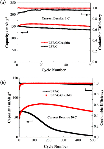 | ||
| Fig. 7 Variation of capacity and coulombic efficiency verses number of cycles for LFP/C and LFP/C/graphite composites at (a) 1C, and (b) 50C current density. | ||
The N2 adsorption–desorption isotherms and pore size distribution of the LFP/C and LFP/C/graphite materials are presented in Fig. S3.† At a relative pressure of 0–1.0, it exhibited a type IV hysteresis, which demonstrated a characteristic of mesoporous materials. The LFP/C/graphite materials have a BET surface area of 27 m2 g−1, which was much higher than that of LiFePO4/C materials (8.7 m2 g−1). The pore size distribution indicated that the presence of multiple pore scales, including micropores (0.4–2 nm), mesopores (2–50 nm) and macropores (50–200 nm). Two figures of pore size distribution showed the same curve type. The pore size was mainly concentrated at 10–50 nm in the inset of figures, which was consistent with type IV hysteresis in N2 adsorption–desorption isotherms. The difference of two curve was that the quantity of mesopores (2–50 nm) in pore size distribution of LFP/C/graphite materials was much higher than that of mesopores materials. This demonstrated that the addition of Graphite into LFP/C materials contributed to the formation of 3D network which increased BET surface and mesopores of LFP/C/graphite materials.
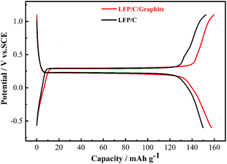
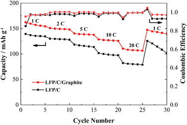
The charge/discharge curves of LFP/C and LFP/C/graphite electrodes are illustrated in Fig. 8 observed between −0.6 V and 1.2 V. The electrodes' charge/discharge curves plateau at around 0.3 V indicates LFP redox processes. It is important that the potential difference between the charge/discharge voltage plateaus in aqueous rechargeable lithium batteries is nearly similar, since this is related to voltage lag and electrode material polarization. The charge/discharge curves of LFP/C/graphite electrode indicate enhanced values of discharge capacity and alike voltage plateaus as compared to LFP/C electrode which maybe owed to the polarization of electrodes due to the addition of graphite. Fig. 9 illustrates the rate capabilities of the LFP/C and LFP/C/graphite electrodes at various current rates with 10-time cycling. The varying reversible capacities of LFP/C and LFP/C/graphite electrodes at 1C, 2C, 5C, 10C, and 20C rates are presented in Fig. 9. Remarkably, the LFP/C/graphite electrode revealed best capacity at different current densities. The capacity of LFP/C electrode is observed to be 140, 135, 125, 85 and 73 mA h g−1, while the capacity for LFP/C/graphite electrode is 163, 151, 148, 142, and 128 mA h g−1 at 1, 2, 5, 10, and 20C, respectively. This could potentially be the result of a number of factors, including the electrode and aqueous solution having a lot of contact surface, the intercalation and de-intercalation of lithium ions or homogenous particle size distribution. When the aqueous rechargeable lithium battery is recycled at 1C current rate, it showed almost 93% retention for LFP/C/graphite as compared to LFP/C. This indicates that the addition of graphite on carbon coated LFP particles exhibit good rate performance due to low resistant graphite. Therefore, the graphite significantly improves the conductive networks in LFP/C electrode that accomplish as current collectors, thus enhance the electrochemical properties.
Conclusions
The two-step superficial scheme is employed to synthesize LFP/C composites and subsequently layered with graphite to achieve LFP/C/graphite. The carbon coated LFP particles are evenly wrapped by 3D network. This practice is awfully effective in exploiting commercially available graphite without any alterations. XRD confirms the crystalline orthorhombic olivine structure of carbon coated LFP particles with graphite with no extra phases. The SEM and TEM micrographs indicate presence of several small crystallites and connections between the carbon coated LFP particles and the graphite. During the course of charge and discharge, the LFP/C/graphite promise rapid ions and electrons transport. The existence of graphite with carbon coated LFP particles improved surface contacts between aqueous electrolyte and the electrode. This structure provides conductive pathways and as a result this LFP/C/graphite composite shows remarkable lithium storage properties. Furthermore, the carbon coated LFP particles with emulsion of graphite illustrates high discharge capacity, good cyclic stability, high coulombic efficiency (97%) and better capacity retention. Henceforth, the electrochemical estimations pondered that the LFP/C/graphite composites with super low-cost are favorable contenders being used as cathode materials in rechargeable aqueous lithium batteries.Conflicts of interest
There are no conflicts to declare.Acknowledgements
This work was supported by the Natural Science Foundation of Shaanxi Provincial Education Department (No. 22JK0595), the Scientific Research Program Funded by Shaanxi Provincial Education Department Program (No. 22JP100), the Natural Science Foundation of Shaanxi Province (2023-JC-QN-0615) and the Youth Innovation Team of Shaanxi Universities. We acknowledged the testing and analysis from Xi'an Key Laboratory of Advanced Photo-electronics Materials and Energy Conversion Device in Xijing University (China), and the Key Laboratory of Advanced Functional Materials and Mesoscopic Physics in Xi'an Jiaotong University (China).Notes and references
- P. A. Johns, M. R. Roberts, Y. Wakizaka, J. H. Sanders and J. R. Owen, Electrochem. Commun., 2009, 11, 2089–2092 CrossRef CAS
.
- Y. G. Wang, J. Yi and Y. Y. Xia, Adv. Energy Mater., 2012, 2, 830–840 CrossRef CAS
.
- M. S. Zhao, G. L. Huang, B. Zhang, F. Wang and X. P. Song, J. Power Sources, 2012, 211, 202–207 CrossRef CAS
.
- C. Yang, J. Chen, X. Ji, T. P. Pollard, X. Lu, C. J. Sun, S. Hou, Q. Liu, C. Liu and T. Qing, Nature, 2019, 569, 245–250 CrossRef CAS PubMed
.
- N. Alias and A. A. Mohamad, J. Power Sources, 2015, 274, 237–251 CrossRef CAS
.
- J. L. Liu, C. H. Xu, Z. Chen, S. B. Ni and Z. X. Shen, Green Energy Environ., 2018, 3, 20–41 CrossRef
.
- D. Bin, Y. P. Wen, Y. G. Wang and Y. Y. Xia, J. Energy Chem., 2018, 27, 1521–1535 CrossRef
.
- W. Li, J. R. Dahn and D. S. Wainwright, Science, 1994, 264, 1115–1118 CrossRef CAS PubMed
.
- L. Suo, O. Borodin, T. Gao, M. Olguin, J. Ho, X. Fan, C. Luo, C. Wang and K. Xu, Science, 2015, 350, 938–943 CrossRef CAS PubMed
.
- Y. Yamada, K. Usui, K. Sodeyama, S. Ko, Y. Tateyama and A. Yamada, Nat. Energy, 2016, 1, 16129–16137 CrossRef CAS
.
- C. Lin, K. Sun and M. Ge, Sci. Adv., 2020, 6, 7129 CrossRef PubMed
.
- L. Chen, J. Zhang and Q. Li, ACS Energy Lett., 2020, 5, 968–974 CrossRef CAS
.
- A. Tron, Y. N. Jo, S. Oh, Y. Park and J. Mun, ACS Appl. Mater. Interfaces, 2017, 9, 2391–12399 CrossRef PubMed
.
- P. Byeon, H. Lee, J. Choi and S. Y. Chung, ChemSusChem, 2019, 12, 787–794 CrossRef CAS PubMed
.
- X. H. Liu, T. Saito, T. Doi, S. Okada and J. I. Yamaki, J. Power Sources, 2009, 189, 706–710 CrossRef CAS
.
- W. Tang, Y. Hou, F. Wang, L. Liu, Y. Wu and K. Zhu, Nano Lett., 2013, 13, 2036–2040 CrossRef CAS PubMed
.
- Y. Wu, F. Wang, S. Xiao, Z. Chang and Y. Yang, Chem. Commun., 2013, 49, 9209–9211 RSC
.
- R. Ruffo, C. Wessells, R. A. Huggins and Y. Cui, Electrochem. Commun., 2009, 11, 247–249 CrossRef CAS
.
- J. Y. Luo and Y. Y. Xia, Adv. Funct. Mater., 2007, 17, 3877–3884 CrossRef CAS
.
- G. Yuan, J. Bai, T. N. L. Doan and P. Chen, Mater. Lett., 2015, 158, 248–251 CrossRef CAS
.
- J. S. Sanchez, S. Jaime, J. Xu, Z. Xia, J. Sun, L. E. Asp and V. Palermo, Compos. Sci. Technol., 2021, 208, 108768 CrossRef CAS
.
- K. W. Gebrewahid, T. N. Vo, S. So, J. Hur and I. T. Kim, Appl. Surf. Sci., 2021, 553, 149496 CrossRef
.
- L. Suhyun, J. Jang, D. Lee, J. Kim and J. Mun, Int. J. Energy Res., 2022, 46, 6480–6486 CrossRef
.
- F. Wang, L. Suo, Y. Liang, C. Yang, F. Han, T. Gao, W. Sun and C. Wang, Adv. Energy Mater., 2017, 7, 1600922 CrossRef
.
- D. Guodong, Y. Xi, X. Tian, Y. Zhu, Y. Zhou, C. Deng, H. Zhu and A. Natarajan, Ceram. Int., 2019, 45, 18247–18254 CrossRef
.
- W. Duan, M. Zhao, J. Shen, S. Zhao and X. Song, Dalton Trans., 2017, 46, 12019 RSC
.
- M. M. Mubasher, M. Mumtaz, M. Hassan, N. U. R. Lashari, Z. Ahmad, M. T. Khan and M. Ali, J. Mater. Sci.: Mater. Electron., 2020, 31, 13909–13918 CrossRef CAS
.
- W. Xiang, Z. G. Wu, E. H. Wang, M. Z. Chen, Y. Song, J. B. Zhang, Y. J. Zhong, S. L. Chou, J. H. Luo and X. D. Guo, J. Power Sources, 2016, 329, 94–103 CrossRef CAS
.
- B. Sun, D. Xu, Z. Wang, Y. Zhan and K. Zhang, Battery Energy, 2022, 1, 20220001 CrossRef
.
- X. Wang, Y. Wang, J. Hao, Y. Liu, H. Xiao, Y. Ma, L. Chen, Y. Huang and G. Yuan, Energy Storage Mater., 2022, 50, 454–463 CrossRef
.
- D. Kornilov, T. R. Penki, A. Cheglakov and D. Aurbach, Battery Energy, 2022, 1, 20210002 CrossRef CAS
.
- L. Wang, L. Xie, Y. Song, X. Liu, H. Zhang and X. He, Battery Energy, 2023, 2, 20220025 CrossRef CAS
.
- Y. Guo, Y. Zhang and H. Lu, Battery Energy, 2022, 1, 20210014 CrossRef CAS
.
- Q. Zhu, M. Wang, B. Nan, H. Shi, X. Zhang, Y. Deng, L. Wang, Q. Chen and Z. Lu, J. Power Sources, 2017, 362, 147–159 CrossRef CAS
.
Footnote |
| † Electronic supplementary information (ESI) available. See DOI: https://doi.org/10.1039/d3ra04143c |
| This journal is © The Royal Society of Chemistry 2023 |

