 Open Access Article
Atomic layer deposition of Y2O3 films using a novel liquid homoleptic yttrium precursor tris(sec-butylcyclopentadienyl)yttrium [Y(sBuCp)3] and water†
Akihiro Nishida *ab,
Tsukasa Katayamacd and
Yasutaka Matsuoc
aGraduate School of Chemical Sciences and Engineering, Hokkaido University, N13W8, Kita-ku, Sapporo 060-8628, Japan. E-mail: nishida.akihiro.y9@elms.hokudai.ac.jp
bSemiconductor Materials Department, Electronic Materials Development Laboratory, ADEKA CORPORATION, 7-2-34 Higashiogu, Arakawa-ku, Tokyo 116-8553, Japan. E-mail: a.nishida@adeka.co.jp
cResearch Institute for Electronic Science (RIES), Hokkaido University, N21W10, Sapporo 001-0021, Japan
dJST-PRESTO, Kawaguchi, Saitama 332-0012, Japan
First published on 12th September 2023
Abstract
Atomic layer deposition (ALD) of Y2O3 thin films was studied using a novel homoleptic yttrium ALD precursor: tris(sec-butylcyclopentadienyl)yttrium [Y(sBuCp)3]. Y(sBuCp)3 is a liquid at room temperature. The thermogravimetry curve for Y(sBuCp)3 is clean, with no indication of decomposition or residue formation. Thermogravimetry–differential thermal analysis measurements showed that Y(sBuCp)3 is stable for 18 weeks at 190 °C. Y(sBuCp)3 has a homoleptic structure. Thus, a reduction in manufacturing costs is expected compared to those associated with heteroleptic precursors because additional chemical synthesis steps are usually necessary to produce heteroleptic compounds. In addition, ALD of Y2O3 was demonstrated using Y(sBuCp)3 and water as a co-reactant. The deposition temperature was varied from 200 to 350 °C. The growth rate was 1.7 Å per cycle. In addition, neither carbon nor nitrogen contamination was detected in the Y2O3 films by X-ray photoelectron spectroscopy. Furthermore, smooth films were confirmed by X-ray secondary-electron microscopy. The root-mean-square roughness was measured to be 0.660 nm by atomic force microscopy. Metal–insulator–semiconductor (MIS) Pt/Y2O3/p-Si devices were fabricated to evaluate the electrical properties of the Y2O3 films. An electric breakdown field of −6.5 MV cm−1 and a leakage current density of ∼3.2 × 10⁻³ A cm−2 at 1 MV cm−1 were determined. The permittivity of Y2O3 was estimated to be 11.5 at 100 kHz. Therefore, compared with conventional solid precursors, Y(sBuCp)3 is suitable for use in ALD manufacturing processes.
Introduction
Yttrium oxide (Y2O3) is well known to exhibit attractive properties, including a high melting point (∼2410 °C), high dielectric constant (∼15), wide bandgap (∼5.5 eV), and high refractive index.1 It has been used in several industrial applications such as ceramics, dielectric insulators, superconductors, optical films,2 protective films,3 and buffer layers. In the energy field, thin-film solid oxide fuel cells (TF-SOFCs) are promising as next-generation high-efficiency energy sources.4,5 To fabricate TF-SOFCs, defect-free yttria-stabilized zirconia (YSZ) and yttria-doped ceria (YDC) electrolyte films with thicknesses less than 100 nm are required.6–8 In microelectronics, Y2O3 is promising as a next-generation gate insulating film material. Recent studies have revealed that the dielectric constant (k) and crystal stability of materials such as ZrO2, HfO2, and La2O3 are improved by doping with Y2O3.9–12 These Y2O3-containing thin films are mainly deposited by physical vapor deposition (PVD),2,11,12 chemical vapor deposition (CVD),3 or atomic layer deposition (ALD)4,6–9,13 processes.The importance of the ALD process has recently increased because of its ability to prepare thin films with a uniform smooth surface.13,14 However, almost all conventional yttrium ALD precursors are poorly suited for industrial use because they are solids at room temperature. As an example, tris(2,2,6,6,-tetramethyl-3,5-heptanedione)yttrium [Y(thd)3] is the most commonly used yttrium ALD precursor. However, Y(thd)3 is difficult to use in mass production processes because it is a solid and has a high melting point of 176 °C. The ALD growth rate [i.e., growth per cycle (GPC)] for Y(thd)3 is 0.2 Å per cycle.15 As an example, a film thickness greater than 100 nm is typically required for protective films; thus, a higher GPC is desirable.3 When Y(thd)3 is used in the ALD process, its GPC is low; hence, productivity is too low for thicker films to be obtained.
Several yttrium ALD precursors have been studied thus far. One such example is tris(N,N′-diisopropylacetamidinate) [Y(iPr2amd)3].16 It exhibits a relatively high ALD growth rate of 0.8 Å per cycle; however, its melting point is greater than 220 °C. Cyclopentadienyl-type ALD precursors have also been reported. Tris(cyclopentadienyl) yttrium [Y(Cp)3] and tris(methylcyclopentadienyl) yttrium [Y(MeCp)3] have high ALD growth rates of 1.5–1.8 and 1.2–1.3 Å per cycle, respectively.17 However, their melting points are 296 and 124 °C, respectively.
Ideally, the melting point of yttrium ALD precursors should be lowered to overcome several problems, including clogging of supply lines, particle formation, and complex purification processes. Alkyl-Cp-type yttrium precursors [Y(RCp)3], which have comparatively low melting points, have also been recently developed.18–20 Tris(ethylcyclopentadienyl) yttrium [Y(EtCp)3], tris(n-propylcyclopentadienyl) yttrium [Y(nPrCp)3], and tris(isopropylcyclopentadienyl) yttrium [Y(iPrCp)3] have melting points of 48, 66, and 55 °C, respectively. Tris(n-butylcyclopentadienyl) yttrium [Y(nBuCp)3] is a liquid precursor at room temperature, and a crystalline Y2O3 film has been prepared by ALD using [Y(nBuCp)3].21 However, with increasing alkyl chain lengths, the vapor pressure was found to worsen compared with that for precursors with shorter chain lengths.
Another approach to improving several precursor properties is to develop heteroleptic precursors. The liquid yttrium ALD precursor (iPrCp)2Y(iPr-amd), which has a high vapor pressure and a growth rate of 0.6 Å per cycle, has been reported.22 However, the synthetic routes for producing such heteroleptic precursors are usually complicated. In addition, the disproportionation reaction of the precursors must be suppressed. As a result, the cost of heteroleptic precursors is greater than that of homoleptic precursors.
Given the above considerations, from the perspectives of manufacturing cost, disproportionation reaction, melting point, and vapor pressure, we expected homoleptic alkyl-Cp-type yttrium precursors [Y(RCp)3] to be promising as a basic structure; we therefore modified its alkyl chain structure. In the present study, the yttrium precursor tris(sec-butylcyclopentadienyl)yttrium(III) [Y(sBuCp)3] (Table 1), which is a liquid at room temperature, was developed as an industrially preferred precursor. We carried out ALD testing using the [Y(sBuCp)3] precursor with water as a co-reactant.
Experimental
Characterization of Y(sBuCp)3 precursor
The 1H-NMR data for Y(sBuCp)3 were obtained using a JEOL ECA-400. Thermogravimetric analysis (TGA) was carried out at 10 Torr in an Ar-filled glovebox using a Rigaku ThermoPlus2 TG8120. Thermal decomposition temperature was measured by differential scanning calorimetry (DSC) with a Bruker AXS DSC 3100.ALD testing of Y(sBuCp)3 precursor with water
Y2O3 films were deposited using a commercial ALD apparatus (NCD Lucida D100) equipped with a cross-flow ALD reactor; water was used as the co-reactant. Prior to deposition, Si(100) substrates were cut to 25 mm × 25 mm and subsequently cleaned with 0.5% HF solution for 1 min to remove the native oxide layer. The cleaned wafers were dried using N2 gas and immediately loaded into the ALD chamber. Before the ALD process, the wafer was heated for 30 min to stabilize its temperature. The Y(sBuCp)3 was provided by ADEKA (CAS no. 847153-22-4, product name: Y-5000). The Y(sBuCp)3 precursor was added to a stainless steel canister and heated at 175 °C. The precursor supply method was vapor drawing using Ar carrier gas at 50 sccm. The chamber pressure was controlled at ∼0.75 Torr by Ar process gas.Characterization of deposited Y2O3 films
Yttrium deposition was measured by X-ray fluorescence (XRF) analysis using a Rigaku ZSX Primus IVi. The stoichiometry and elemental bonding states in the films were characterized by X-ray photoelectron spectroscopy (XPS) using a Thermo Fisher Scientific K-Alpha. The film morphology and thickness were studied by field-emission scanning electron microscopy (FE-SEM) and atomic force microscopy (AFM) with a Hitachi High-Tech S-4800 and a Bruker Multimode 8, respectively. The scanning mode in AFM measurement is “Peak Force Tapping”. The tip for AFM is Bruker SCANASYST-AIR. The film thickness and the crystallinity were evaluated by X-ray reflectivity (XRR) and X-ray diffraction (XRD) measurements using a Rigaku Ultima IV.Electric characterization of Y2O3 films
The electric properties of the obtained Y2O3 films were evaluated by preparing metal–insulator–semiconductor (MIS) structures of Pt/Y2O3/p-Si. The deposition temperature of the Y2O3 layer was 300 °C. The Pt electrodes were deposited onto the Y2O3 films through a shadow mask at room temperature by DC magnetron sputtering using a Sanyu Electron SC-701MC. The thicknesses of the Pt electrode, Y2O3 layer, and p-Si substrate were 100 nm, 19.4 nm and 0.5 mm, respectively. Capacitance–voltage (C–V) curves for the MIS structure were recorded using a precision LCR meter (Agilent, 4980A). The current–voltage (I–V) curves were also acquired (Keithley, Sourcemeter 2450). The probe station was coaxial probe.Results and discussion
Chemical identification of Y(sBuCp)3 precursor
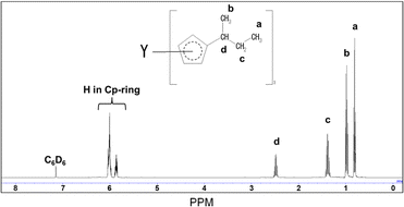
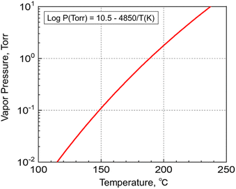
The synthesized Y(sBuCp)3 was confirmed by 1H-NMR measurement. Fig. 1 shows the 1H-NMR spectrum of Y(sBuCp)3. The signal of each proton on the cyclopentadienyl ring appeared at 6.011 and 5.866 ppm as a multiplet. The coupling to the proton on the tertiary carbon atom showed as a hexaplet at 2.489 ppm. The methyl group on the sec-butyl group showed as a multiplet at 0.982 ppm. The ethyl group on the sec-butyl group showed as a multiplet at 1.391 ppm (2H) and a triplet at 0.819 ppm (3H). Each peak was overlapped or a multiplet because the sec-butyl Cp ligand has a stereocenter on the alpha carbon. On the basis of the 1H NMR analysis results, Y(sBuCp)3 was considered a chiral compound.Fig. 2 shows the vapor pressure variations with temperature of the Y(sBuCp)3 precursor. The vapor pressure of Y(sBuCp)3 was 0.1 Torr at 149 °C. The vapor pressure of Y(nBuCp)3 has been reported to be 0.1 Torr at 150 °C.20 Thus, the introduction of a branched alkyl structure slightly improved the vapor pressure.
Fig. 3(a) shows the TGA curves for Y(sBuCp)3 and conventional precursors such as the solid precursor Y(EtCp)3 and the liquid precursor Y(nBuCp)3. The curve for Y(sBuCp)3 is clean, with no indication of decomposition or residue formation at 10 Torr. The 50% volatile temperature (TG1/2) was 197 °C. The TG1/2 for Y(EtCp)3 was 186 °C; it thus exhibits greater volatility than Y(sBuCp)3 even though it is a solid. Compared with Y(nBuCp)3, Y(sBuCp)3 exhibits greater volatility. The TG1/2 for Y(nBuCp)3 was 219 °C because of its linear and alkyl chain structure. For hydrocarbon molecules with the same molecular weight, a compound with a branched structure will exhibit a lower boiling point than one with a linear structure.23 A branched alkyl chain of the precursor is critical for achieving greater volatility. With the introduction of a sec-butyl group, the volatility of the Y(sBuCp)3 precursor was improved and became similar to that of the Y(EtCp)3 precursor.
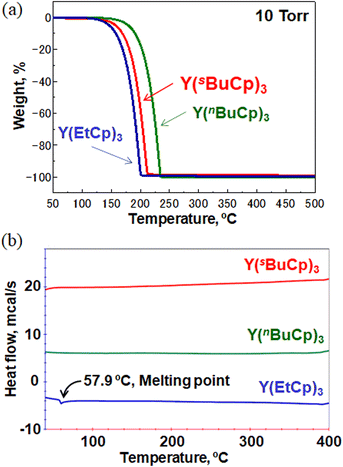 | ||
| Fig. 3 (a) TGA curves for Y(sBuCp)3 and conventional precursors Y(EtCp)3 and Y(nBuCp)3 (b) DSC thermograms of Y(sBuCp)3 and conventional precursors Y(EtCp)3 and Y(nBuCp)3. | ||
Fig. 3(b) shows DSC thermograms for the Y(sBuCp)3 and conventional precursors. A thermal decomposition peak was not observed at a temperature less than 400 °C for any of the precursors. These results indicate that the Y(RCp)3 base structure exhibits high thermal stability. Y(sBuCp)3 and Y(nBuCp)3 were liquid precursors; melting was therefore not observed in the investigated temperature range. Y(sBuCp)3 has three chiral centers; thus, four types of diastereomers are possible, excluding enantiomers, because it contains eight stereoisomer structures (i.e., RRR, SRR, RRS, SRS, RSR, SSR, RSS, and SSS). In general, stereoisomer mixtures have lower melting points than single-structure compounds because of poor crystallization of the molecule.24 Y(sBuCp)3 is expected to have a lower melting point than Y(nBuCp)3. That is, Y(sBuCp)3 is expected to remain a liquid over a wide temperature range.
Long-term thermal stability of Y(sBuCp)3 precursor
An ALD precursor is heated to a high temperature during the ALD process. Long-term thermal stability at the vaporization temperature for more than a few months is critical for ALDs used industrially, where long-life precursors enable films to be continuously produced without stopping the production line. The DSC results indicate that Y(RCp)3-type complexes exhibit high thermal stability. We therefore evaluated the long-term thermal stability of Y(sBuCp)3 as a novel compound. The Y(sBuCp)3 was heated at 190 °C, which is the temperature at which it vaporizes at 1 Torr, and periodically characterized by TGA and 1H-NMR. The results show very clean TG curves before and after the sample was heated at 190 °C for 18 weeks in Fig. S1 of ESI.† Fig. 4 shows TGA residue recorded during the long-term thermal stability test. The TG residue of Y(sBuCp)3 did not change before or after it was heated at 190 °C for 18 weeks. Fig. S2 of ESI† presents 1H-NMR spectra acquired during the long-term thermal stability test. The spectrum of Y(sBuCp)3 did not change before or after it was heated at 190 °C for 18 weeks. Therefore, Y(sBuCp)3 was confirmed to exhibit excellent long-term thermal stability and volatility for at least 18 weeks.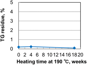 | ||
| Fig. 4 TG residue recorded during long-term thermal stability test of Y(sBuCp)3 at 190 °C for 18 weeks. | ||
ALD testing of Y(sBuCp)3 precursor with water
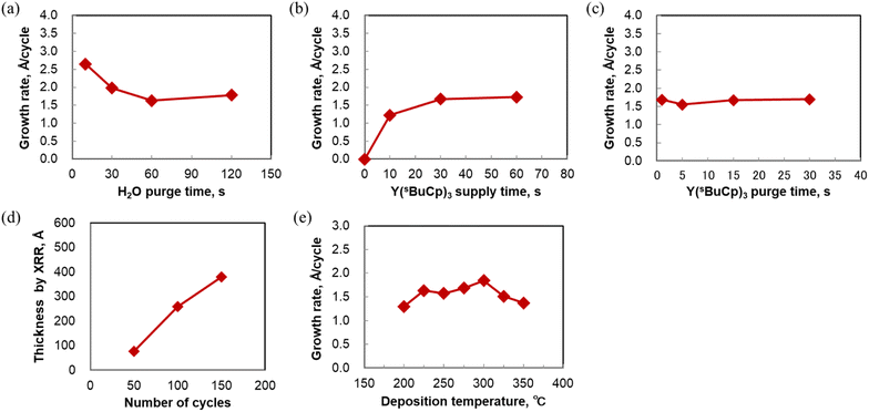
The ALD sequence involves dosing and purging steps for the metal complex, and the use of a co-reactant. The dosing and purging times should be optimized to enable the fabrication of ultra-thin, conformal films with high uniformity. Experiments to determine the optimal dosing and purging times were carried out for ALD of Y2O3 using the Y(sBuCp)3 precursor with water as a co-reactant. To remove the moisture in the ALD chamber, various water purge times were investigated at 250 °C. Fig. 5(a) shows that a higher growth rate was achieved at 10 and 30 s, although a constant growth rate was observed when the purge time was longer than 60 s. The results show that adsorption of Y(sBuCp)3 was affected by remaining moisture when the water purge time was shorter than 30 s in our ALD reactor. Therefore, the deposition was carried out using a water purge time of 60 s.Fig. 5(b) shows that saturation occurred when the Y(sBuCp)3 supply time on the Si substrate was varied at 250 °C. The results show that self-limited film growth occurred. The Y(sBuCp)3 was confirmed to be saturated when the supply time was 30 s or longer. Under our experimental conditions, the saturation time was long compared with those for conventional precursors.17,18,21 Y(sBuCp)3 exhibits volatility similar to that of Y(RCp)3; we therefore considered that this difference was caused by our experimental conditions. To reduce the saturation time, the partial pressure of Y(sBuCp)3 should be increased in the ALD chamber to improve precursor adsorption onto the substrate. For further improvement, a higher precursor heating temperature and bubbling of the precursor supply are promising. The saturated film growth rate was ∼1.7 Å per cycle at 250 °C.
The Y(sBuCp)3 purge time was also optimized. Fig. 5(c) shows the Y(sBuCp)3 purge time dependence of the film growth rate at 250 °C. A constant growth rate was observed when the purge time was 15 s or longer. Small variations in the growth rate were confirmed at shorter purge times because of incomplete purging of the metal precursor. Because carbon contamination originating from the ligand was a concern in this range of short purge times, a purge time of at least 15 s was considered necessary.
On the basis of the above results, the standard pulsing ALD sequence was designed as follows: 30 s supply of metal precursor with carrier gas, followed by 15 s Ar purge, 0.2 s pulse of water, and finally 60 s purge with Ar gas. We used this standard sequence to evaluate the ALD behavior of Y(sBuCp)3.
Fig. 5(d) shows the film thickness as a function of the number of ALD cycles. The film thickness was measured by XRR. The thickness increased linearly with increasing number of ALD cycles at 250 and 300 °C. These results indicate that the film grew at a constant rate; thus, Y(sBuCp)3 demonstrated excellent thickness control characteristics. The results thus far verify the linear dependence and the saturation behavior; we therefore concluded that Y(sBuCp)3 exhibits an ALD-type growth mode.
ALD behavior of Y(sBuCp)3 at 250 °C was confirmed; we therefore next investigated the deposition temperature dependence in the range 200–400 °C. Fig. 5(e) shows the growth rate at various deposition temperatures. In this experiment, Y2O3 films were deposited by ALD onto Si substrates for 50 cycles. The growth rate reached 1.5 Å per cycle at 250 °C. The maximal growth rate at 300 °C was found to be 1.8 Å per cycle. The growth rate was 1.3–1.8 Å per cycle in the temperature range 200–350 °C. These values are similar to those reported for thermal ALD of Y2O3 using cyclopentadienyl yttrium precursors such as Y(Cp)3, Y(MeCp)3, Y(EtCp)3, Y(iPrCp)3, and Y(nBuCp)3.17,18,21,25 The growth rate decreased with increasing deposition temperature beyond 300 °C. The yttrium intensity detected by XRF also decreased when the deposition temperature was greater than 300 °C because Y(sBuCp)3 was desorbed as a result of the greater thermal energy at higher temperatures during the ALD process. According to the DSC measurement results, the thermal decomposition temperature of Y(sBuCp)3 is greater than 400 °C. Thus, we deduced that the decrease in the growth rate was not a result of thermal decomposition but rather desorption at higher temperatures.
We compared the growth rate achieved using Y(sBuCp)3 as a precursor with those achieved using conventional precursors. Y(thd)3 showed a low growth rate of 0.2 Å per cycle with O3 as a co-reactant.10 Y(iPr2amd)3 enabled Y2O3 film growth at 0.8 Å per cycle.11 The heteroleptic precursor (iPrCp)2Y(iPr-amd) showed a growth rate of 0.6 Å per cycle.16 We concluded that Y(sBuCp)3 enables a higher growth rate than the conventional precursors, thereby enabling greater productivity of Y2O3 films.
Film properties of Y(sBuCp)3 precursor with water
The film concentration and impurities in the films were measured by XPS analysis. Fig. 6(a–c) shows XPS depth profiles for films deposited at (a) 200 °C, (b) 250 °C, and (c) 300 °C. The results confirm that high-purity Y2O3 was deposited at all three investigated temperatures. The oxygen concentration slightly increased with increasing deposition temperature. For the above films, the Y/O ratio was found to be 0.74, 0.71, and 0.69, respectively, indicating the formation of hydroxylated or reduced Y2O3−x at low deposition temperatures.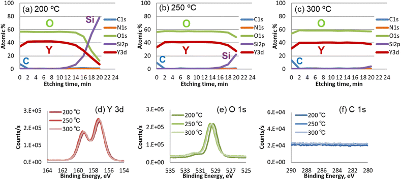 | ||
| Fig. 6 XPS depth profiles for Y2O3 films deposited at (a) 200 °C, (b) 250 °C, and (c) 300 °C. XPS spectra of Y2O3 films deposited at (d) 200 °C, (e) 250 °C, and (f) 300 °C. | ||
Fig. 6(d–f) shows the Y 3d, O 1s, and C 1s regions of the XPS spectra of the deposited films. The Y main peaks (d) appeared at 156.8 and 158.8 eV. The O 1s spectra (e) of the Y2O3 films show a Y–O peak at ∼529.5 eV. The peak at 200 °C was shifted to lower energy because of an insufficient oxidation reaction due to the low deposition temperature. No peak attributable to Y–OH was observed in the spectra of any of the films. In addition, neither C (f) nor N impurities were detected in any of the films.
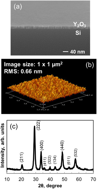
Fig. 7(a) shows FE-SEM images of the Y2O3 films deposited onto p-type Si(100) substrates. Continuous films with a smooth surface and a thickness of 23.1 nm were deposited at 200 °C. Isolated particles were not detected on the surface.
Fig. 7(b) shows a three-dimensional AFM image of a Y2O3 film deposited onto a p-type Si(100) substrate at 200 °C. The film thickness was 23.1 nm, and the scanned area was 1.0 μm × 1.0 μm. The imaging results indicate that the film had a smooth surface. The root mean square (RMS) roughness determined by AFM measurement was 0.66 nm, which is lower than the roughness values of Y2O3 films deposited using conventional precursors.16,17
Fig. 7(c) shows that the 23.1 nm-thick Y2O3 film on a Si substrate was crystalline, as indicated by XRD measurements. The results confirmed that the as-deposited Y2O3 film was crystallized without annealing. Peaks associated with (222), (400), (332), (431), (440), and (622) planes were observed, indicating that the crystal phase is mainly cubic.26,27 A monoclinic-rich film can be deposited at high temperatures. In addition, the structure of the film is affected by the oxygen partial pressure, deposition pressure, and the substrate. The XRD pattern showed no additional peaks caused by impurities.
These film characterization results confirm that the Y(sBuCp)3 precursor can easily provide a high-quality Y2O3 film.
Electric properties of Y2O3 films
Fig. 8(a) shows C–V curves for the Pt/Y2O3/p-Si MIS capacitor. The thickness and deposition temperature of the Y2O3 layer were 19.4 nm and 300 °C, respectively, and the area of the Pt top electrode was 0.015 mm2. The measurement was conducted at 25 °C and a frequency of 100 kHz. The voltage range was from 3 V to −3 V. The sweep rate was 0.48 V s−1. When a negative bias was applied, the capacitance value was 80 pF. From these results, the dielectric constant for the Y2O3 layer was estimated to be 11.5, which is similar to previously reported values of ∼10 (Y(Cp)3 and Y(MeCp)3).17,28 However, when a positive bias was applied to the MIS capacitor, the capacitance substantially decreased because of the formation of a depletion layer in the p-Si.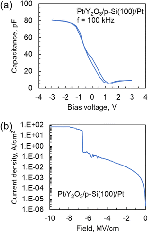 | ||
| Fig. 8 (a) C–V and (b) leakage current density vs. electric field curves for the Pt/Y2O3/p-Si capacitor. The deposition temperature for the Y2O3 layer was 300 °C. | ||
Fig. 8(b) shows leakage current density vs. electric field curves for the Pt/Y2O3/p-Si MIS capacitor. The voltage range was from 0 V to −20 V. The sweep rate and compliance current were 0.48 V s−1 and 100 mA, respectively. The leakage current density at 1 MV cm−1 and breakdown electric field were approximately 3.2 × 10⁻³ A cm−2 and 6.5 MV cm−1, respectively. These values are comparable to those for a previously reported MIS capacitor fabricated using a Y2O3 layer prepared from solid or heteroleptic ALD precursors.17,29 Thus, these results indicate that a Y2O3 layer with high electronic performance could be attained even when a liquid homoleptic ALD precursor was used.
Conclusions
We have demonstrated ALD of Y2O3 films using a newly developed yttrium precursor, Y(sBuCp)3. Y(sBuCp)3 is a liquid at room temperature and exhibits high volatility because of its branched alkyl chain structure. In addition, a lower melting point is expected because of its stereoisomerism. This molecular design imparted the precursor with industrially preferred properties. Y(sBuCp)3 also exhibits high thermal stability, exhibiting a lifetime of at least 18 weeks at 190 °C. This evaluation is ongoing, so the lifetime might be longer than 18 weeks. In addition, like the conventional Y(RCp)3 precursor, Y(sBuCp)3 exhibits a high growth rate and a wide ALD window. The deposited Y2O3 films exhibit high purity, high crystallinity, and a smooth surface. The Y2O3 films prepared from Y(sBuCp)3 also exhibit high electronic performance. Therefore, we conclude that Y(sBuCp)3 is an attractive Y2O3 precursor for industrial use.Conflicts of interest
There are no conflicts to declare.Acknowledgements
We are grateful to ADEKA for providing the Y(sBuCp)3 precursor and 1H-NMR, vapor pressure, TGA, and DSC data. This work was partly supported by “Crossover Alliance to Create the Future with People, Intelligence and Materials” and Advanced Research Infrastructure for Materials and Nanotechnology (ARIM) Japan from the Ministry of Education, Culture, Sports, Science and Technology (MEXT).References
- K. J. Hubbard and D. G. Schlom, J. Mater. Res., 1996, 11, 2757–2776 CrossRef CAS.
- G. Atanassov, R. Thielsch and D. Popov, Thin Solid Films, 1993, 223, 288–292 CrossRef CAS.
- G. Bonnet, M. Lachkar, J. P. Larpin and J. C. Colson, Solid State Ionics, 1994, 72, 344–348 CrossRef CAS.
- I. Chang, S. Ji, J. Park, M. H. Lee and S. W. Cha, Adv. Energy Mater., 2015, 5(10), 1402251 CrossRef.
- J. Park, I. Chang, J. Y. Paek, S. Ji, W. Lee, S. W. Cha and J.-M. Lee, CIRP Ann., 2014, 63, 513–516 CrossRef.
- J. H. Shim, C. C. Chao, H. Huang and F. B. Prinz, Chem. Mater., 2007, 19, 3850–3854 CrossRef CAS.
- Z. Fan, C.-C. Chao, F. Hossein-Babaei and F. B. Prinz, J. Mater. Chem., 2011, 21, 10903–10906 RSC.
- J. Park, Y. Lee, I. Chang, G. Y. Cho, S. Ji, W. Lee and S. W. Cha, Energy, 2016, 116, 170–176 CrossRef CAS.
- C. Bernay, A. Ringuedé, P. Colomban, D. Lincot and M. Cassir, J. Phys. Chem. Solids, 2003, 64, 1761–1770 CrossRef CAS.
- S. J. Wang, C. K. Ong, S. Y. Xu, P. Chen, W. C. Tjiu, A. C. H. Huan, W. J. Yoo, J. S. Lim, W. Feng and W. K. Choi, Semicond. Sci. Technol., 2001, 16, L13–L16 CrossRef CAS.
- Y. Zhao, K. Kita, K. Kyuno and A. Toriumi, Appl. Phys. Lett., 2006, 89, 252905 CrossRef.
- J. Y. Dai, P. F. Lee, K. H. Wong, H. L. W. Chan and C. L. Choy, J. Appl. Phys., 2003, 94, 912–915 CrossRef CAS.
- J. Y. Paek, I. Chang, J. H. Park, S. Ji and S. W. Cha, Renewable Energy, 2014, 65, 202–206 CrossRef CAS.
- S. M. George, Chem. Rev., 2010, 110, 111–131 CrossRef CAS PubMed.
- M. Putkonen, T. Sajavaara, L. S. Johansson and L. Niinistö, Chem. Vap. Deposition, 2001, 7, 44–50 CrossRef CAS.
- P. de Rouffignac, J.-S. Park and R. G. Gordon, Chem. Mater., 2005, 17, 4808–4814 CrossRef CAS.
- J. Niinistö, M. Putkonen and L. Niinistö, Chem. Mater., 2004, 16, 2953–2958 CrossRef.
- P. Majumder, G. Jursich, A. Kueltzo and C. Takoudis, J. Electrochem. Soc., 2008, 155(8), G152–G158 CrossRef CAS.
- C. Dubourdieu, presented in part at the ALD conference, 2011 Search PubMed.
- N. Blasco, presented in part at the ALD conference, Kyoto, Japan, 2014 Search PubMed.
- A. I. Abdulagatov, R. R. Amashaev, K. N. Ashurbekova, S. M. Ramazanov, D. K. Palchaev, A. M. Maksumova, M. K. Rabadanov and I. M. Abdulagatov, Russ. Microelectron., 2019, 48, 1–12 CrossRef CAS.
- I.-S. Park, Y. Chan Jung, S. Seong, J. Ahn, J. Kang, W. Noh and C. Lansalot-Matras, J. Mater. Chem. C, 2014, 2, 9240–9247 RSC.
- P. Y. Bruice, Handbook of Organic Chemistry, 5th edn, Kagakudojin, 2009 Search PubMed.
- R. J. Prankerd and M. Z. Elsabee, Thermochim. Acta, 1995, 248, 147–160 CrossRef CAS.
- R. Xu, S. K. Selvaraj, N. Azimi and C. G. Takoudis, ECS Trans., 2013, 50, 107–116 CrossRef.
- K. Jayasankar, A. Pandey, B. K. Mishra and S. Das, Mater. Chem. Phys., 2016, 171, 195–200 CrossRef CAS.
- R. Marder, R. Chaim, G. Chevallier and C. Estournes, Mater. Sci. Eng., A, 2011, 528, 7200–7206 CrossRef CAS.
- N. Boysen, D. Zanders, T. Berning, S. M. J. Beer, D. Rogalla, C. Bock and A. Devi, RSC Adv., 2021, 11, 2565–2574 RSC.
- J.-S. Lee, W.-H. Kim, I.-K. Oh, M.-K. Kim, G. Lee, C.-W. Lee, J. Park, C. Lansalot-Matras, W. Noh and H. Kim, Appl. Surf. Sci., 2014, 297, 16–21 CrossRef CAS.
Footnote |
| † Electronic supplementary information (ESI) available. See DOI: https://doi.org/10.1039/d3ra05217f |
| This journal is © The Royal Society of Chemistry 2023 |


