 Open Access Article
Advancing structural batteries: cost-efficient high-performance carbon fiber-coated LiFePO4 cathodes†
Jaehoon Choi,
Omid Zabihi ,
Mojtaba Ahmadi and
Minoo Naebe
 *
*
Carbon Nexus, Institute for Frontier Materials (IFM), Deakin University, Waurn Ponds, VIC, 3216, Australia. E-mail: minoo.naebe@deakin.edu.au
First published on 18th October 2023
Abstract
Structural batteries (SBs) have gained attention due to their ability to provide energy storage and structural support in vehicles and airplanes, using carbon fibers (CFs) as their main component. However, the development of high-performance carbon fiber-based cathode materials for structural batteries is currently limited. To address this issue, this study proposes a cost-efficient and straightforward method for creating a high-performance structural lithium iron phosphate (LiFePO4) positive electrode by coating carbon fibers at mild temperatures and pressures. The resulting cathode demonstrated a high LiFePO4 loading (at least 74%) and a smooth coating, as confirmed by X-ray spectroscopy, scanning electron microscopy, and Raman spectroscopy. This structural cathode exhibited a capacity of 144 mA h g−1 and 108 mA h g−1 at 0.1 C and 1.0 C, respectively. Additionally, the LiFePO4 cathode displayed excellent electrochemical properties, with a capacity retention of 96.4% at 0.33 C and 81.2% at 1.0 C after 300 cycles. Overall, this study presents a promising approach for fabricating high-performance structural batteries with enhanced energy storage and structural capabilities.
Introduction
The demand for eco-friendly transportation has been on the rise worldwide, partly driven by carbon-neutral regulations set to take effect by 2050. Consequently, electric vehicles (EVs) have garnered increasing interest from investors in research and development as well as commercialization.1,2 Lithium-ion batteries (LiBs) are widely investigated for use in EVs. However, one of the key challenges faced by EVs is their relatively shorter range per charging cycle, when compared to combustion engine vehicles. Therefore many studies are currently focused on enhancing the energy density of LiBs to address this limitation and make EVs more practical for daily use.3–5Carbon fibers (CFs) are being utilized as a replacement for heavy car panels due to their lightweight and strong characteristics. This makes them an ideal material for improving energy efficiency by reducing the weight of vehicles.6–8 Additionally, the graphitic structure of CFs allow energy storage9,10 and its outstanding electrical conductivity makes it ideal to be used as a current collector.11,12 Due to these unique characteristics CFs have been investigated to realize structural batteries which enables not only carrying mechanical load, but also simultaneously storing energies.13,14 A structural composite battery is made up of carbon fibres that act as a reinforcing structure, electrode, and solid polymeric electrolyte which serves as both a separator and an electrolyte.13,15–17
At the early stage of research for structural batteries, there were significant focuses on developing CFs based anode as well as efforts to integrate CFs to fabricate CFs-composite electrode via solid polymer electrolyte.18,19 However, there have not been many research on development of positive electrodes for structural batteries. To fabricate a positive electrode for structural batteries, there are various cathode materials such as LiCoO2, LiMn2O4, LiFePO4, which can be used in the conventional LiBs due to not only its considerable theoretical capacity (170 mA h g−1) but also structural stability.20–22
Liu et al. reported carbon nanofiber based lithium cobalt oxide (LiCoO2) cathode holding a specific capacity of 90 mA h g−1.19 However, carbon nanofiber is not only being used more commonly as an additive rather than a current collector, but also requires a slow dry casting process to remove the plasticizer (propylene carbonate). Recently, coating cathode material onto CFs via electrophoretic deposition (EPD) and autoclave method have been investigated for use in structural batteries.11,23,24 Hagberg et al. reported that LiFePO4 coated onto polyacrylonitrile (PAN)-based CFs tow via EPD method delivers a specific capacity of 108 mA h g−1 at 0.1 C.11 However, the coating performance was dependent on the distance between Pt wire (counter electrode) and CFs (working electrode) at EPD instrumental set-up, making it difficult to obtain a high yield. Park et al. reported a method using vacuum bag and autoclave to coat LiFePO4 onto woven carbon fibre, and recorded a capacity of 112 mA h g−1 at 0.1 C with 0.82 retention (at 1.0 C) after 500 cycles.23 Despite obtaining such a good capacity using autoclave for coating, makes this method less cost efficient.
In this study, we utilized a feasible cost-efficient method to fabricate a LiFePO4 coated CFs cathode electrode for a composite structural battery. To the best of our knowledge, this approach has not been reported elsewhere. The CFs tow performs not only as current collector, but also provides mechanical stiffness and strength. The choice of LiFePO4 as the cathode material is based not only on its non-toxic properties, but also on its cost-effectiveness when compared to other cathode materials. This makes it highly beneficial for scale-up applications. LiFePO4 cathode slurry are composed of LiFePO4 particles, carbon black particles and PVDF to bind the particles. To seek an optimum LiFePO4 slurry ratio, different ratios of LiFePO4 were prepared. The morphology and properties of LiFePO4 coatings on CFs tow were investigated. Electrochemical analysis was conducted to evaluate capacity, rate performance and cycling life. Furthermore, tensile testing for the structural cathode was carried out to investigate not only mechanical strength, but also the crack propagation of LiFePO4 coating on the surface of CFs.
Experimental
Materials
LiFePO4 (LFP) whose particle size ranging between 100 and 300 nm was supplied by TARGRAY. Carbon black (CB, SUPER C65) with dimension of 20 nm was purchased from TIMCAL. Anhydrous 1-methyl-2-pyrrolidinone (NMP, purity of 99.5%) and polyvinylidene fluoride (PVDF) with molecular weight 534![[thin space (1/6-em)]](https://www.rsc.org/images/entities/char_2009.gif) 000 measured by GPC were purchased from Sigma Aldrich. Furthermore, lithium hexafluorophosphate solution in ethylene carbonate and dimethyl carbonate (1.0 M LiPF6 in EC/DEC = 50/50, battery grade) electrolyte were also obtained from Sigma-Aldrich. All purchased chemicals were utilised without any pre purifications. Unidirectional (UD) T300 CF tow (A38-6k) were obtained from DowAksa (Turkey).
000 measured by GPC were purchased from Sigma Aldrich. Furthermore, lithium hexafluorophosphate solution in ethylene carbonate and dimethyl carbonate (1.0 M LiPF6 in EC/DEC = 50/50, battery grade) electrolyte were also obtained from Sigma-Aldrich. All purchased chemicals were utilised without any pre purifications. Unidirectional (UD) T300 CF tow (A38-6k) were obtained from DowAksa (Turkey).
Fabrication of UD carbon fibre substrate
To prepare a CFs substrate, UD CFs tow (6k) was placed onto a Si rubber plate with dimensions of 75 mm × 25 mm. Subsequently, the tow was secured with tape. Next, the CFs were wrapped with a release film layer, peel-ply strip, and breather on a 30 × 30 cm stainless-steel plate. Afterward, the PVDF binder, consisting of 0.2 g of PVDF dissolved in 1 mL of NMP, was used for vacuum infusion. The prepared mold was then placed in a hot press for the coating step at 80 °C with an applied pressure of approximately 3 bar for 30 minutes. This process was carried out in a vacuum environment.Fabrication of LiFePO4/CF structural cathode
Developed UD carbon fibres substrate was used to fabricate the LiFePO4/CF structural cathode for this study. To fabricate LiFePO4 slurry for the CFs structural cathode, different ratios of LiFePO4, carbon black, NMP and PVDF as listed in Table 1 were prepared.| LiFePO4 (wt%) | Carbon black (wt%) | PVDF (wt%) | NMP |
|---|---|---|---|
| 92 | 2 | 6 | 1![[thin space (1/6-em)]](https://www.rsc.org/images/entities/char_2009.gif) : :![[thin space (1/6-em)]](https://www.rsc.org/images/entities/char_2009.gif) 4 ratio (PVDF 4 ratio (PVDF![[thin space (1/6-em)]](https://www.rsc.org/images/entities/char_2009.gif) : :![[thin space (1/6-em)]](https://www.rsc.org/images/entities/char_2009.gif) NMP) in 2 mL of acetone NMP) in 2 mL of acetone |
| 90 | 4 | 6 | |
| 88 | 4 | 8 | |
| 78 | 10 | 12 |
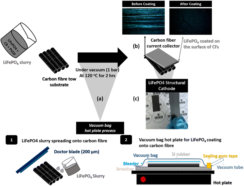
The composed cathode materials were poured into a mixed solvent (0.48 mL of NMP + 2 mL of acetone) and stirred using a magnet stirrer at 40 °C for 30 min. Then, the product was sonicated for the same temperature and duration in a bath sonicator and stirred for further 30 min at 40 °C prior to coating onto the CFs substrate. The cathode slurry was applied to a stainless-steel plate using a doctor blade with a thickness of 200 μm. Next, a CFs substrate, which was attached to a Si rubber plate, was placed on top of the electrode slurry. The same vacuum bagging procedure used to prepare the CFs substrate was then conducted. The vacuum-sealed mold was transferred to a hot press and kept at 120 °C for 2 hours under 1 bar pressure, as shown in Scheme 1.
Characterization methods
![[thin space (1/6-em)]](https://www.rsc.org/images/entities/char_2009.gif) :
:![[thin space (1/6-em)]](https://www.rsc.org/images/entities/char_2009.gif) DEC of 1
DEC of 1![[thin space (1/6-em)]](https://www.rsc.org/images/entities/char_2009.gif) :
:![[thin space (1/6-em)]](https://www.rsc.org/images/entities/char_2009.gif) 1) as working electrode, reference electrode, separator, and electrolyte. All coin-cell fabrication was conducted in a glove box with argon environment (<1 ppm O2 and H2O), and LiFePO4/CF was vacuum dried in a conventional oven for 24 h at 60 °C for 24 before the cell fabrication step.
1) as working electrode, reference electrode, separator, and electrolyte. All coin-cell fabrication was conducted in a glove box with argon environment (<1 ppm O2 and H2O), and LiFePO4/CF was vacuum dried in a conventional oven for 24 h at 60 °C for 24 before the cell fabrication step.Results and discussions
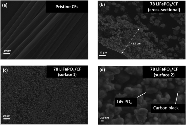
1. Structural characterization of the LiFePO4/CF electrode compositeScheme 1 shows the entire process of the LiFePO4 cathode coating on to UD CFs substrate using a facile vacuum compression molding press. In Fig. 1, the microstructure of 78 LiFePO4/CF electrode composite was investigated via SEM. As illustrated in Fig. 1(a) and (b), LiFePO4 slurry was adequately adhered onto the surface of pre-prepared CFs tow substrate. Furthermore, the thickness of 78 LiFePO4/CF is confirmed as 42.9 μm via the cross-section image in Fig. 1(b) which is comparable to the commercial electrodes having 20–30 μm thickness. Fig. 1(c) shows the LiFePO4 coating onto the surface of CFs at low magnification which is uniform.
Fig. 1(d) reveals the distribution of coated particles (LiFePO4 and carbon black) on the surface of CFs, demonstrating a good particle distribution on the coating surface. In addition, the particle distribution on the surface of LiFePO4 coated CFs was evaluated via EDX (Fig. S2†) as it enables identifications of key elements (Fe and P from LiFePO4, F from PVDF) distribution and no distinct defects was found.
Fig. 2(a) shows XRD graphs of LiFePO4 and LiFePO4/CF. All evaluated diffraction peaks can be indexed to crystalline orthorhombic LiFePO4 phase according to JCPDS card no. is 40–1499.25,26 In Fig. 2(a), the CFs peak disappeared from the XRD pattern of LiFePO4/CF electrode composite, indicating that LiFePO4 is coated on to the surface of CFs substrate. Furthermore, by comparing the XRD pattern between the electrode composite and LiFePO4, no significant peaks were found in the LiFePO4/CF composite, revealing that vacuum compression moulding approach did not influence the LiFePO4 crystalline structure.
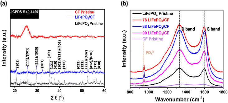 | ||
| Fig. 2 Microstructural evaluation of neat materials (CFs pristine and LiFePO4 powder) and different LiFePO4 slurry applied structural cathode composite via (a) XRD and (b) Raman. | ||
In Fig. 2(b), two distinct peaks were appeared at 1335 cm−1 and 1596 cm−1 which is related to D-band (sp3 hybridization, disordered carbon) and G-band (sp2 hybridization, graphite), correspondingly.27,28 Xie et al. reported that the intensity ratio of ID/IG is an index of the degree of disorder carbon layers.29 The ID/IG ratio of 78 LiFePO4/CF is 1.01 which is lower in comparison with 88 LiFePO4/CF (1.03) and 90 LiFePO4/CF (1.05). This suggests that 78 LiFePO4/CF has graphite-like coating layers compared to other composite samples which present more amorphous coating layers, thereby it may influence the lithium-ion interaction while performing electrochemical analysis.
Shi et al. reported the peak between 500 and 1100 cm−1 in Raman spectra can be associated with vibration of the Fe–O and PO43− group.29 As shown in Fig. 2(b), all LiFePO4 coated CFs composite displayed PO43− peak at 950 cm−1, and hence these are another evidence of LiFePO4 coating performance on the surface of CFs which is in agreement with XRD result.
2. The half-cell performance
For the half-cell performance of the LiFePO4 composite electrodes, the half-cell was fabricated as depicted on Fig. 3.
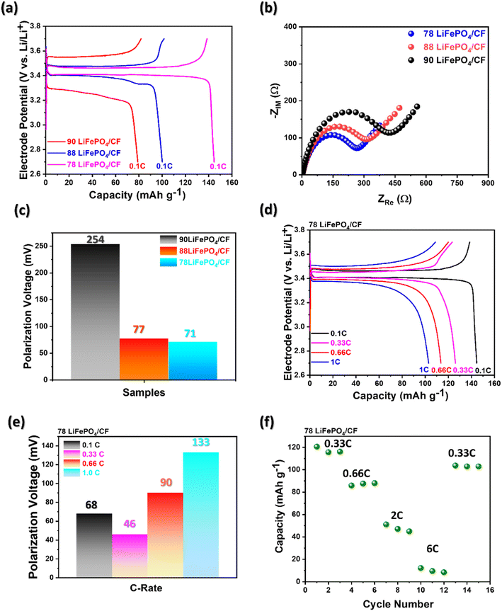
As illustrated in Fig. 4(a), the results of electrochemical performance of the fabricated cathode at 0.1 C exhibit that the different LiFePO4 electrode slurry ratios influenced the capacity difference. The electrochemical performance at 0.1 C reveals that 78 LiFePO4/CF indicated the highest capacity as 144 mA h g−1 compared to the other ratio samples. As mentioned earlier about the LiFePO4 coating performance in regards with ID/IG ratio, this result may be obtained by more graphitized coating structure, which enables better lithium-ion intercalation, on 78 LiFePO4/CF compared to other samples. Sanchez et al. reported that the lower overall resistance between electrolyte and electrode attaining from electrochemical impedance spectroscopy (EIS) can be reflected to superior capacity performance.29 In addition, Ferg and Vuuren reported a battery cell having higher internal resistance (Rct) could not perform well compared to a cell with lower Rct.30
As shown in Fig. 4(b) and Table 2, the resistance between electrolyte and electrode for 78 LiFePO4/CF, 88 LiFePO4/CF and 90 LiFePO4/CF samples were obtained via the intercept on the real axis (Zre) in the intrinsic resistance (Rs) of the spectra to be 3.19, 2.99 and 2.84 Ω cm−1, respectively. In addition, the semicircle between high and low frequencies indicates the Rct and it was the smallest in 78LiFePO4/CF (263.6 Ω) compared to 88LiFePO4/CF (313.6 Ω) and 90LiFePO4/CF (417.1 Ω). According to obtained resistances, the interfacial redox reaction is more likely to be favoured in 78LiFePO4/CF compared to other samples.
| Weight of LFP (mg cm−2) | Rs (Ω cm−1) | Rct (Ω) | |
|---|---|---|---|
| 78 LiFePO4/CF | 7.53 | 3.19 | 263.6 |
| 88 LiFePO4/CF | 5.78 | 2.99 | 313.6 |
| 90 LiFePO4/CF | 4.94 | 2.84 | 417.1 |
Cui et al. reported that cycle stability can be enhanced by reducing interfacial resistance between the electrolyte and electrode, as well as decreasing polarization voltage during charging and discharging.31 Additionally, Wang et al. found that an increase in cell polarization leads to capacity fading.32 Fig. 4(c) shows the lowest polarization voltage at 78 LiFePO4/CF compared to other slurry composition samples, and it also exhibits the smallest Rct value as mentioned earlier. These results explain the capacity fading observed in different slurry compositions in terms of electrochemical performance at 0.1 C, as shown in Fig. 4(a), by correlating it with interfacial resistance and polarization voltage.
Fig. 4(d) shows charge/discharge profiles at different C-rates for a CFs electrode coated via a vacuum hot press with the slurry composition 78![[thin space (1/6-em)]](https://www.rsc.org/images/entities/char_2009.gif) :
:![[thin space (1/6-em)]](https://www.rsc.org/images/entities/char_2009.gif) 10
10![[thin space (1/6-em)]](https://www.rsc.org/images/entities/char_2009.gif) :
:![[thin space (1/6-em)]](https://www.rsc.org/images/entities/char_2009.gif) 2 (LiFePO4
2 (LiFePO4![[thin space (1/6-em)]](https://www.rsc.org/images/entities/char_2009.gif) :
:![[thin space (1/6-em)]](https://www.rsc.org/images/entities/char_2009.gif) PVDF
PVDF![[thin space (1/6-em)]](https://www.rsc.org/images/entities/char_2009.gif) :
:![[thin space (1/6-em)]](https://www.rsc.org/images/entities/char_2009.gif) CB). The voltage plateau of 78 LiFePO4/CF was indicated as around 3.4 V vs. Li+/Li, attributed to the redox reaction of Fe2+/Fe3+ in agreement of the previous studies.33,34 Furthermore, the specific capacity is decreasing via increasing C-rate from 0.1 C to 1.0 C in agreement with the previous reported.35,36 Interestingly, Fig. 4(e) shows increasing trend in polarization voltage by increasing C-rate, and hence it could be evaluated as a crucial parameter on battery performance.
CB). The voltage plateau of 78 LiFePO4/CF was indicated as around 3.4 V vs. Li+/Li, attributed to the redox reaction of Fe2+/Fe3+ in agreement of the previous studies.33,34 Furthermore, the specific capacity is decreasing via increasing C-rate from 0.1 C to 1.0 C in agreement with the previous reported.35,36 Interestingly, Fig. 4(e) shows increasing trend in polarization voltage by increasing C-rate, and hence it could be evaluated as a crucial parameter on battery performance.
As shown in Fig. 4(f), the performance of 78LiFePO4/CF reduces with enhancing C-rate. Nevertheless, it is reversible procedure because the initial capacity was returned by returning to 0.33 C.
Fig. 5(a–c) show a long-term cycling stability which is a key parameter for an electrode of Li-ion batteries. Two different conditions for long-term cycling stability were conducted not only at 0.33 C over 100 cycles, but also 1.0 C over 300 cycles. Fig. 5(a) and (b) exhibit slightly fading the specific capacity at 0.33 C and at 1.0 C over 100 cycles. However, no significant capacity drop was observed and also high-capacity retentions of 96.4% at 0.33 C and 95.8% at 1.0 C were obtained. Previous works have reported that the capacity fade occurred by growth of the negative electrode SEI, consequently it causes a continuous capacity fading.37,38
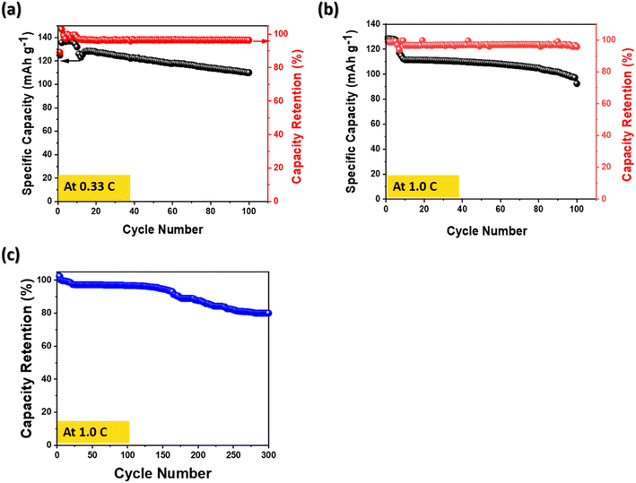 | ||
| Fig. 5 Long-term cycling stability for 78 LiFePO4/CF composite electrode (a) at 0.33 C-rate over 100 cycle (b) at 1.0 C-rate over 100 cycle and (c) coulombic efficiency at 1.0 C-rate over 300 cycle. | ||
In addition, the capacity over 300 cycles exhibited 81.2% retention, demonstrating that the performance degradation was not occurred rapidly at a high C-rate. By comparing the obtained electrochemical performance with the previous studies in Table 3, the structural cathode prepared via a vacuum bag hot plate process reveals a potential to utilize for structural batteries.
| Method | Carbon fibre | Materials | Capacity (mA h g−1) | Cycling retention (%) | Mass loading (mg cm−2) | Ref. | |
|---|---|---|---|---|---|---|---|
| 1 | Hot press (at 120 °C under 1 bar pressure) | 6k tow | LiFePO4/carbon black/PVDF | 144 (at 0.1 C) | 96.4 at 0.33 C, 95.8 at 1.0 C (100 cycles) and 81.2 at 1.0 C (300 cycles) | 4.7 | This work |
| 2 | Electro-deposition (EPD) | 12k tow | LiFePO4/carbon black/PVDF | 110 (at 0.1 C) | 62 at 1.0 C (500 cycles) | n/a | 11 |
| Acetone and surfactant for EPD | |||||||
| 3 | Electro-deposition (EPD) | 12k tow | LiFePO4/carbon black/graphene oxide (GO) | 131 (at 0.1 C) | 91 at 1.0 C (500 cycles) | 1 | 39 |
| DMF and surfactant for EPD | |||||||
| 4 | Electro-deposition (EPD) | Carbon cloth | LiFePO4/carbon black | 110 (at 0.1 C) | 80 at 0.5 C (300 cycles) | 20 | 24 |
| EtOH | |||||||
| 5 | Electro-deposition (EPD) | Carbon cloth | LiFePO4/carbon black | 140 (at 0.1 C) | 84 at 0.1 C (100 cycles) | 10 | 24 |
| EtOH | |||||||
| 6 | Autoclave | Woven fabric | LiFePO4/carbon black/PVDF | 112 (at 0.1 C) | 82 at 1.0 C(500 cycles) | n/a | 23 |
3. Mechanical properties of structural cathode
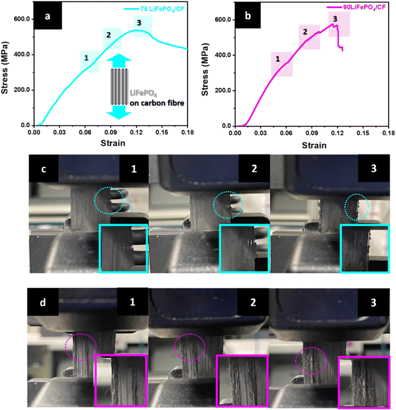
The tensile tests were carried out to study mechanical properties of structural CFs cathodic composite as well as investigate propagating crack regions while applying force. Fig. 5 exhibits the results of tensile test and photography of LiFePO4 coating crack propagation on the surface of CFs. The first surface crack was initiated in the region 1 in Fig. 6(a) and confirmed through a photography of the region 1 in Fig. 6(c). According to Fig. 6(a) and (b), the surface crack propagation was continued until the fracture region appeared in the stress–strain curve. In addition, the crack propagation occurred at the outer surface area of the composite electrode. However, the resultants of 90 LiFePO4/CF in Fig. 6(b and d) showed a significant surface crack propagation at the centre and outer surface area compared to 78 LiFePO4/CF. Interestingly after the test, 78 LiFePO4/CF sustained its structure as well as LiFePO4 coating on the surface of CFs compared to 90 LiFePO4/CF. This phenomenon may be attributed by the different ratio of PVDF in the cathode slurry. Because it influences determining the degree of binding LiFePO4 and CB particles on the surface of CFs.38–40
Furthermore, the optimized structural cathode composite (78 LiFePO4/CF) in Table 4 shows high mechanical performances, 538.7 MPa tensile strength, 4.30 GPa elastic modulus and 64.4 MJ m−3 toughness. This result indicates that higher binder affects not only effectively holding active materials, but also physically bonding to CFs substrate.41,42 According to these results, a vacuum bag hot press process to coat LiFePO4 on CFs is a potential applicable method for a structural composite battery.
| Sample | Young's modulus (GPa) | Stress at elongation at break (MPa) | Toughness (MJ m−3) |
|---|---|---|---|
| a Toughness was calculated by integrating the tensile stress–strain curve. | |||
| 78 LiFePO4 | 4.30 ± 0.23 | 538.7 ± 0.99 | 64.4 ± 0.14 |
| 90 LiFePO4 | 4.74 ± 1.06 | 517.9 ± 79.27 | 42.5 ± 5.09 |
Conclusions
In summary, we employed a straightforward approach to fabricate a LiFePO4-coated CFs composite electrode for structural batteries. Based on XRD and Raman analyses, the LiFePO4 slurry was well-coated onto the surface of CFs. Furthermore, the 78 LiFePO4/CF composite exhibited thicker graphite coating layers compared to other samples, as evidenced by the ratio of ID/IG, which also confirmed its influence on electrochemical performance. The morphology of the LiFePO4 coating on the CFs' surface, as observed via SEM, displayed not only flawless surface coating but also clear separation between the LiFePO4 coating layer and CFs in the cross-sectional view.The optimized cathode composite half-cell, with high mechanical performance (538.7 MPa tensile strength and 4.12 GPa elastic modulus), achieved a discharge capacity of 144 mA h g−1 at 0.1 C and 102 mA h g−1 at 1.0 C. Additionally, long-term cycling stability demonstrated 96.4% (over 100 cycles) and 81.2% (over 300 cycles) at 0.33 C and 1.0 C, respectively. These results suggest that the developed LiFePO4-coated CFs composite electrode holds great promise as a candidate for cathode materials in structural battery development.
Conflicts of interest
There are no conflicts to declare.Acknowledgements
The authors gratefully acknowledge the Australian Research Council (ARC) Research Hub for Future Fibres (IH140100018) funded by the Australian Government for their financial support.References
- S. Solaymani, CO2 emissions patterns in 7 top carbon emitter economies: The case of transport sector, Energy, 2019, 168, 989–1001, DOI:10.1016/j.energy.2018.11.145.
- M. Pichler, N. Krenmayr, E. Schneider and U. Brand, EU industrial policy: Between modernization and transformation of the automotive industry, Environ. Innov. Soc. Transit., 2021, 38, 140–152, DOI:10.1016/j.eist.2020.12.002.
- C. C. Kwasi-Effah and T. Rabczuk, Dimensional analysis and modelling of energy density of lithium-ion battery, J. Energy Storage, 2018, 18, 308–315, DOI:10.1016/j.est.2018.05.002.
- X. Lv, W. Wei, B. Huang and Y. Dai, Achieving high energy density for lithium-ion battery anodes by Si/C nanostructure design, J. Mater. Chem. A, 2019, 7, 2165–2171, 10.1039/C8TA10936B.
- X. Dong, L. Chen, X. Su, Y. Wang and Y. Xia, Flexible Aqueous Lithium-Ion Battery with High Safety and Large Volumetric Energy Density, Angew. Chem., Int. Ed., 2016, 55, 7474–7477, DOI:10.1002/anie.201602766.
- A. Jacob, Carbon fibre and cars – 2013 in review, Reinf. Plast., 2014, 58, 18–19, DOI:10.1016/S0034-3617(14)70036-0.
- H. Adam, Carbon fibre in automotive applications, Mater. Des., 1997, 18, 349–355, DOI:10.1016/S0261-3069(97)00076-9.
- K. Badii, J. S. Church, G. Golkarnarenji, M. Naebe and H. Khayyam, Chemical structure based prediction of PAN and oxidized PAN fiber density through a non-linear mathematical model, Polym. Degrad. Stab., 2016, 131, 53–61, DOI:10.1016/j.polymdegradstab.2016.06.019.
- W. Kang, N. Deng, J. Ju, Q. Li, D. Wu and X. Ma, et al., A review of recent developments in rechargeable lithium–sulfur batteries, Nanoscale, 2016, 8, 16541–16588, 10.1039/C6NR04923K.
- V. Ghanooni Ahmadabadi, K. Shirvanimoghaddam, R. Kerr, N. Showkath and M. Naebe, Structure-rate performance relationship in Si nanoparticles-carbon nanofiber composite as flexible anode for lithium-ion batteries, Electrochim. Acta, 2020, 330, 135232, DOI:10.1016/j.electacta.2019.135232.
- J. Hagberg, H. A. Maples, K. S. P. Alvim, J. Xu, W. Johannisson and A. Bismarck, et al., Lithium iron phosphate coated carbon fiber electrodes for structural lithium ion batteries, Compos. Sci. Technol., 2018, 162, 235–243, DOI:10.1016/j.compscitech.2018.04.041.
- H. Khayyam, R. N. Jazar, S. Nunna, G. Golkarnarenji, K. Badii and S. M. Fakhrhoseini, et al., PAN precursor fabrication, applications and thermal stabilization process in carbon fiber production: Experimental and mathematical modelling, Prog. Mater. Sci., 2020, 107, 100575, DOI:10.1016/j.pmatsci.2019.100575.
- L. E. Asp and E. S. Greenhalgh, Structural power composites, Compos. Sci. Technol., 2014, 101, 41–61, DOI:10.1016/j.compscitech.2014.06.020.
- J. Galos, K. Pattarakunnan, A. S. Best, I. L. Kyratzis, C.-H. Wang and A. P. Mouritz, Energy Storage Structural Composites with Integrated Lithium-Ion Batteries: A Review, Adv. Mater. Technol., 2021, 6, 2001059, DOI:10.1002/admt.202001059.
- J. Choi, O. Zabihi, R. J. Varley, B. Fox and M. Naebe, Enhancement of ionic conduction and mechanical properties for all-solid-state polymer electrolyte systems through ionic and physical bonding, Mater. Today Chem., 2022, 23, 100663, DOI:10.1016/j.mtchem.2021.100663.
- J. Choi, O. Zabihi, R. J. Varley, B. Fox and M. Naebe, High Performance Carbon Fiber Structural Batteries Using Cellulose Nanocrystal Reinforced Polymer Electrolyte, ACS Appl. Mater. Interfaces, 2022, 14, 45320–45332, DOI:10.1021/acsami.2c11034.
- J. Choi, O. Zabihi, R. Varley, J. Zhang, B. L. Fox and M. Naebe, Multiple Hydrogen Bond Channel Structural Electrolyte for an Enhanced Carbon Fiber Composite Battery, ACS Appl. Energy Mater., 2022, 5, 2054–2066, DOI:10.1021/acsaem.1c03354.
- Y. Yu, B. Zhang, M. Feng, G. Qi, F. Tian and Q. Feng, et al., Multifunctional structural lithium ion batteries based on carbon fiber reinforced plastic composites, Compos. Sci. Technol., 2017, 147, 62–70, DOI:10.1016/j.compscitech.2017.04.031.
- P. Liu, E. Sherman and A. Jacobsen, Design and fabrication of multifunctional structural batteries, J. Power Sources, 2009, 189, 646–650, DOI:10.1016/j.jpowsour.2008.09.082.
- I. J. Davidson, R. S. McMillan, J. J. Murray and J. E. Greedan, Lithium-ion cell based on orthorhombic LiMnO2, J. Power Sources, 1995, 54, 232–235, DOI:10.1016/0378-7753(94)02074-D.
- J.-M. Chen, C.-H. Hsu, Y.-R. Lin, M.-H. Hsiao and G. T.-K. Fey, High-power LiFePO4 cathode materials with a continuous nano carbon network for lithium-ion batteries, J. Power Sources, 2008, 184, 498–502, DOI:10.1016/j.jpowsour.2008.04.022.
- J. Ying, C. Jiang and C. Wan, Preparation and characterization of high-density spherical LiCoO2 cathode material for lithium ion batteries, J. Power Sources, 2004, 129, 264–269, DOI:10.1016/j.jpowsour.2003.10.007.
- H.-W. Park, M.-S. Jang, J.-S. Choi, J. Pyo and C.-G. Kim, Characteristics of woven carbon fabric current collector electrodes for structural battery, Compos. Struct., 2021, 256, 112999, DOI:10.1016/j.compstruct.2020.112999.
- K. Moyer, R. Carter, T. Hanken, A. Douglas, L. Oakes and C. L. Pint, Electrophoretic deposition of LiFePO4 onto 3-D current collectors for high areal loading battery cathodes, Mater. Sci. Eng. B, 2019, 241, 42–47, DOI:10.1016/j.mseb.2019.02.003.
- W. Li, A. Garg, M. L. P. Le, C. Ruhatiya, L. Gao and V. M. Tran, Electrochemical performance investigation of LiFePO4/C0.15−x (x = 0.05, 0.1, 0.15 CNTs) electrodes at various calcination temperatures: Experimental and Intelligent Modelling approach, Electrochim. Acta, 2020, 330, 135314, DOI:10.1016/j.electacta.2019.135314.
- B. Wang, Q. Wang, B. Xu, T. Liu, D. Wang and G. Zhao, The synergy effect on Li storage of LiFePO4 with activated carbon modifications, RSC Adv., 2013, 3, 20024–20033, 10.1039/C3RA44218G.
- A. Manthiram, A. Vadivel Murugan, A. Sarkar and T. Muraliganth, Nanostructured electrode materials for electrochemical energy storage and conversion, Energy Environ. Sci., 2008, 1, 621–638, 10.1039/B811802G.
- X. Liu, X. Liu, B. Sun, H. Zhou, A. Fu and Y. Wang, et al., Carbon materials with hierarchical porosity: Effect of template removal strategy and study on their electrochemical properties, Carbon, 2018, 130, 680–691, DOI:10.1016/j.carbon.2018.01.046.
- Y. Xie, F. Song, C. Xia and H. Du, Preparation of carbon-coated lithium iron phosphate/titanium nitride for a lithium-ion supercapacitor, New J. Chem., 2015, 39, 604–613, 10.1039/C4NJ01169D.
- E. E. Ferg and F. van Vuuren, Comparative capacity performance and electrochemical impedance spectroscopy of commercial AA alkaline primary cells, Electrochim. Acta, 2014, 128, 203–209, DOI:10.1016/j.electacta.2013.08.110.
- Z. Cui, S. Inoue, J. Hassoun and Y. Tominaga, Enhanced Performance of All-Solid-State Li Metal Battery Based on Polyether Electrolytes with LiNO3 Additive, Macromol. Chem. Phys., 2022, 223, 2100396, DOI:10.1002/macp.202100396.
- F. Wang, Z. Lin, L. Liu, X. Wei, S. Lin and L. Dai, et al., Does Polarization Increase Lead to Capacity Fade?, J. Electrochem. Soc., 2020, 167, 090549, DOI:10.1149/1945-7111/ab956b.
- X. Rui, X. Zhao, Z. Lu, H. Tan, D. Sim and H. H. Hng, et al., Olivine-Type Nanosheets for Lithium Ion Battery Cathodes, ACS Nano, 2013, 7, 5637–5646, DOI:10.1021/nn4022263.
- V. A. Sugiawati, F. Vacandio, C. Perrin-Pellegrino, A. Galeyeva, A. P. Kurbatov and T. Djenizian, Sputtered Porous Li-Fe-P-O Film Cathodes Prepared by Radio Frequency Sputtering for Li-ion Microbatteries, Sci. Rep., 2019, 9, 11172, DOI:10.1038/s41598-019-47464-2.
- A. Tomaszewska, Z. Chu, X. Feng, S. O'Kane, X. Liu and J. Chen, et al., Lithium-ion battery fast charging: A review, ETransportation, 2019, 1, 100011, DOI:10.1016/j.etran.2019.100011.
- G. Ning, B. Haran and B. N. Popov, Capacity fade study of lithium-ion batteries cycled at high discharge rates, J. Power Sources, 2003, 117, 160–169, DOI:10.1016/S0378-7753(03)00029-6.
- M. Safari and C. Delacourt, Aging of a Commercial Graphite/LiFePO4 Cell, J. Electrochem. Soc., 2011, 158, A1123, DOI:10.1149/1.3614529.
- A. J. Smith, J. C. Burns, X. Zhao, D. Xiong and J. R. Dahn, A High Precision Coulometry Study of the SEI Growth in Li/Graphite Cells, J. Electrochem. Soc., 2011, 158, A447, DOI:10.1149/1.3557892.
- J. S. Sanchez, J. Xu, Z. Xia, J. Sun, L. E. Asp and V. Palermo, Electrophoretic coating of LiFePO4/Graphene oxide on carbon fibers as cathode electrodes for structural lithium ion batteries, Compos. Sci. Technol., 2021, 208, 108768, DOI:10.1016/j.compscitech.2021.108768.
- X.-M. Fan, Y.-D. Huang, H.-X. Wei, L.-B. Tang, Z.-J. He, C. Yan, J. Mao, K.-H. Dai and J.-C. Zheng, Surface Modification Engineering Enabling 4.6 V Single-Crystalline Ni-Rich Cathode with Superior Long-Term Cyclability, Adv. Funct. Mater., 2022, 32(6), 2109421, DOI:10.1002/adfm.202109421.
- Y.-D. Huang, H.-X. Wei, P.-Y. Li, Y.-H. Luo, Q. Wen, D.-H. Le, Z.-J. He, H.-Y. Wang, Y.-G. Tang, C. Yan, J. Mao, K.-H. Dai, X.-H. Zhang and J.-C. Zheng, Enhancing structure and cycling stability of Ni-rich layered oxide cathodes at elevated temperatures via dual-function surface modification, J. Energy Chem., 2022, 75, 301–309, DOI:10.1016/j.jechem.2022.08.010.
- Y.-d Huang, H.-X. Wei, P.-Y. Li, L.-B. Tang, Y.-H. Luo, X.-M. Fan, C. Yan, J. Mao, K.-H. Dai, H.-Z. Chen, X.-h Zhang and J.-c Zheng, Rational design of surface reconstruction with pinning effect to relieving bulk fatigue for high energy single-crystal Ni-rich cathodes, J. Chem. Eng., 2023, 470, 144254, DOI:10.1016/j.cej.2023.144254.
Footnote |
| † Electronic supplementary information (ESI) available. See DOI: https://doi.org/10.1039/d3ra05228a |
| This journal is © The Royal Society of Chemistry 2023 |

