
 Open Access Article
 This Open Access Article is licensed under a Creative Commons Attribution-Non Commercial 3.0 Unported Licence
Effect of urea and ammonium fluoride ratio on CuCo2S4/NF as a highly efficient HER catalyst
Yifei Dia,
Rongda Zhaoa,
Jun Xiang *a,
Xiangsen Menga,
Fufa Wu*a and
Jing Lib
*a,
Xiangsen Menga,
Fufa Wu*a and
Jing Lib
aSchool of Materials Science and Engineering, Liaoning University of Technology, Jinzhou 121001, China. E-mail: xiangj@lnut.edu.cn; ffwu@lnut.edu.cn; Fax: +86-416-4199650; Tel: +86-416-4199650
bFoshan Graduate School of Innovation, Northeastern University, Foshan 528311, China
First published on 2nd October 2023
Abstract
CuCo2S4 as a spinel-structured transition metal sulfide is a highly effective HER catalyst due to its excellent endurance, low overpotential, and low Tafel slope. In this work, the CuCo2S4/Ni foam (NF) catalysts with various morphologies have been successfully synthesized by controlling the ratio of urea and ammonium fluoride (NH4F) based on the hydrothermal method. Urea and NH4F ratio exhibit a great influence on the microstructure and the HER catalytic performance of CuCo2S4/NF catalysts is discussed in detail.
1. Introduction
The environmental pollution caused by energy consumption has become an important problem faced by modern society. The excessive use of fossil fuels leading to serious environmental problems runs counter to the social responsibility of environmentally sustainable development.1–4 Consequently, in order to reduce the dependence on fossil fuels, renewable energy has been paid more and more attention as a substitute for fossil fuels.5–9 In this regard, hydrogen is considered a promising fuel. Electrochemical reactions that produce oxygen from oxygen evolution reactions (OER) and hydrogen from hydrogen evolution reactions (HER) have attracted a lot of research attention.10,11 Problems of slow reaction and high energy consumption in energy supply technology such as hydrogen production, rechargeable metal–air batteries and renewable fuel cells can be solved by adding catalytic materials to the two semi-reactions.12–23 Currently, Pt-based HER oxides and Ir/Ru OER catalysts are widely used as commercial catalysts in the above-mentioned fields.24 However, the scarcity and high cost of these precious metals impede their extensive use.25–27 Well-designed catalysts prepared using abundant Earth elements such as iron, cobalt, nickel and copper and their derivatives stand out as affordable alternatives.28–30Recently, several non-noble metal catalysts for HER have been reported, such as transition metal chalcogenides.31–41 Transition metal sulfides are promising candidate compounds due to their low cost and easily preparation. For instance, Ji42 et al. used two continuous liquid–solid reactions to design CuS nanowires on copper foil at room temperature. Wang43 et al. synthesized Co3S4/CoP in an Ar atmosphere through simultaneous phosphating and sulfurization of cobalt hydroxide precursors. The material showed a very low HER onset potential, only 34 mV. Geng44 et al. synthesized a metallic phase MoS2 (M-MOS2) with two-dimensional structure for HER catalytic reaction by hydrothermal method. In 0.5 M H2SO4 solution, the overpotential of the electrocatalyst was 175 mV at 10 mA cm−2, and the Tafel slope was 41 mV dec−1. After 1000 cycles by cyclic voltammetry (CV), the current density attenuation of MoS2 nanosheets was less than 12%. Ji45 et al. synthesized 3D flower-like CoS2 microspheres by a typical hydrothermal method and mixed them with IL in isopropyl alcohol solution, and then prepared CoS2-IL catalyst for OER through multi-step solvent evaporation. In 0.1 M KOH solution, a voltage of 1.63 V is required to reach a current density of 10 mA cm−2. The Tafel slope of the electrocatalyst was 81.7 mV dec−1. After 1000 CV cycles, the voltage was only increased by 8 mV at 10 mA cm−2. However, the performance of these electrocatalysts are good at low H coverage, but with the increase of H coverage, the conductivity will decrease significantly.46
CuCo2S4 is a paramagnetic sulfur spinel with ideal AB2S4 molecular formula and metallic properties. Its structure and molecular formula indicate the presence of mixed valence metal cations, so it has high electrical conductivity and electrochemical activity.47,48 Since its features are suitable for various reactions such as HER and OER, CuCo2S4 has been reportedly studied in electrocatalysis applications.49 For instance, Pawar50 et al. directly fabricated highly porous CuCo2O4 nanosheets on nickel foam by electrodeposition approach. In a 1 M KOH solution, the sample exhibited a low overpotential of 260 mV at 20 mA cm−2 with a corresponding Tafel slope of 67 mV dec−1 and an electrochemical surface area (ECSA) value of 4712.5 cm2. At different KOH solution (1 M and 3 M), the capacitance retention rates were 85% and 93%, respectively, after 5000 cycles. Sun51 et al. prepared high-quality Ni doped CuCo2S4 nanoparticles (NCCS NPs) using triethanolamine (TEOA) molecules by a simple hydrothermal method. In 0.5 M H2SO4 solution, the overpotential reached 249 mV at 10 mA cm−2, Tafel slope was 105 mV dec−1, and the double layer capacitance value was 3.4 mF cm−2. After 10 hours stability test of continuous current density of 10 mA m−2, the capacitance retention of NCCS NPs catalyst did not decrease significantly. These studies show that CuCo2S4 can reduce the overpotential, thereby speeding up OER. The increase in OER activity of Cu–Co sulfide is largely due to the synergistic effect of bimetallic structure between copper and other types of atoms to optimize the electronic structure, increase the number of active centers, improve the conductivity, reduce the resistivity, and greatly promote the electrocatalytic activity. However, most OER catalysts perform well in alkaline solutions, the HER-role of CuCo2S4 in alkaline media has not been developed on a large scale, so this material has a certain development potential.52–54 Therefore, we selected CuCo2S4 as HER catalyst to study.
In this work, because of urea and NH4F affect the nucleation capacity of the compound and change the microscopic morphology of CuCo2S4, meaning that different microstructure can be synthesized in different ratio,55,56 which can increase the number of active sites and improve HER performance, CuCo2S4/NF catalysts with different morphology were synthesized by controlling urea and NH4F ratio based on hydrothermal method, and then the influence of urea and NH4F ratio on the microstructure and HER catalytic characteristics of CuCo2S4/NF catalyst was discussed in detail.
2. Experimental section
2.1 Effects of urea and NH4F ratio on the preparation of Cu–Co sulfide catalyst and electrocatalytic HER performance
2.2 Structural characterization of materials
X-ray diffractometer (XRD, D/max-2500/PC−1) with Cu Kα (λ = 1.54 Å) at 2θ range of 10–90° was used to characterize crystal structure of the materials. Field emission scanning electron microscope (FE-SEM, Sigma 500), High Resolution Transmission Electron Microscope (HRTEM) and energy dispersive spectrometer (EDS, Oxford AZtec X-Max 50) were used to analyze the morphology and surface element distribution of the samples. The instrument works at a high voltage of 30 kV, with a vacuum of 133 Pa and an acceleration voltage of 2 kV. X-ray photoelectron spectroscopy (XPS, Thermo Scientific K-Alpha) was used to study the elemental composition and chemical valence state of the sample.2.3 Electrochemical characterization of the materials
The electrochemical performance was tested by Shanghai CHI660E electrochemical workstation. First of all, a three-electrode system was established as the electrochemical test platform, using the as-prepared materials as the working electrode, Hg/HgO as reference electrode, Pt plate as counter electrode, the electrolyte was 1 M KOH aqueous solution, and the current collector was pretreated NF. CuCo2O4 was used as anode and CuCo2S4 as cathode to assemble a two-electrode electrolytic cell. By analyzing CV curve, linear sweep voltammetry (LSV) curve, Tafel curve, electrochemical impedance spectroscopy (EIS) curve, double layer capacitance curve, long-term stability curve the electrochemical performance of electrode materials and practical application ability can be judged. All the potentials measured are converted into reversible hydrogen electrodes (RHE) at 25 °C by Nernst equation:57| ERHE (V) = EHg/HgO (V) + 0.098 + 0.059 pH | (1) |
Over potential can be calculated by following equation:58
| η = E(RHE) − 1.23 V | (2) |
The Tafel slope is given by the following equation:59
η = a + b![[thin space (1/6-em)]](https://www.rsc.org/images/entities/char_2009.gif) log|j| log|j|
| (3) |
The Electrochemical Active Surface Area (ECSA) can be determined by the following equation, where Cdl is the double-layer capacitance of the electrode material and CS is the specific capacitance:60
| ECSA = Cdl/CS |
3. Results and discussion
3.1 Effect of urea on the preparation of CuCo2S4/NF catalyst and its electrocatalytic hydrogen evolution performance
CuCo2S4 with different urea ratios were synthesized by two-step hydrothermal method and calcination, as shown in Fig. 1. Firstly, CuCo2O4 precursors were synthesized on nickel foam. Secondly, the nanosheet-like precursors were calcined in air. Finally, CuCo2S4 was obtained by sulfurization process. | ||
| Fig. 1 Schematic illustration of the synthesis of CuCo2O4/NF nanowires with different urea ratios. | ||
Fig. 2(a) shows the XRD patterns of CuCo2S4/NF catalysts synthesized with different urea ratios. The diffraction peaks can be observed at 2θ values of 16.131°, 26.586°, 31.271°, 37.966°, 46.993°, 49.989°, 54.793°, 57.439°, 61.889°, 64.426°, 68.594°, 77.323° and 81.170°. These diffraction peaks correspond to the (111), (022), (113), (004), (224), (115), (044), (135), (026), (335), (444), (137) and (008) crystal planes of the CuCo2S4 phase (JCPDS no. 42-1450), respectively. Compared with Fig. 2(a) and (b), it can be seen that the CuCo2O4 is completely transformed into CuCo2S4 after the second hydrothermal process.
 | ||
| Fig. 2 (a) XRD patterns of CuCo2S4/NF catalyst with different urea ratios and (b) XRD patterns of CuCo2O4/NF catalyst with different urea ratios. | ||
Fig. 3 is the SEM images of CuCo2S4/NF catalyst. The microstructure of CuCo2S4/NF catalyst prepared with various urea ratio is obviously distinct. Fig. 3(a) and (b) are SEM images of CuCo2S4/NF catalyst prepared with 2 mmol urea. The microstructure of CCS-1 sample is obvious hexagonal nanosheet structure uniformly covered on NF, and the thickness of the single nanosheet is about 500 nm. Fig. 3(c) and (d) are SEM images of CuCo2S4/NF catalyst prepared with 4 mmol urea. The morphology of CCS-2 samples is banded nanosheet structure and uniformly grown on NF substrate. Fig. 3(e) and (f) are SEM images of CuCo2S4/NF catalyst prepared with 8 mmol urea. The morphology of CCS-3 sample is nanosheet structure like willow leaf, and the thickness of nanosheet is about 40 nm. The morphologies of three CuCo2S4/NF catalysts are gradually refined and dispersed with the increment of urea ratio, which will affect the contact between the catalyst surface and the electrolyte. Moreover, the change of morphology will catalytic active sites of CuCo2S4/NF catalysts participate in the electrocatalytic reaction. Thus, HER catalytic performance of CuCo2S4/NF catalyst can be affected by the variable morphology.
 | ||
| Fig. 3 SEM images of CuCo2S4/NF catalyst with different urea ratios: (a and b) SEM images of CCS-1 at low and high magnification, (c and d) SEM images of CCS-2 at low and high magnification, (e and f) SEM images of CCS-3 at low and high magnification. | ||
Fig. 4 shows the CV curves of CuCo2S4/NF catalysts synthesized at various urea ratio in the non-Faraday area at scanning rates of 5–50 mV s−1. Comparison of the electrochemical properties of three CuCo2S4/NF catalysts shows that the CV integral area of CCS-1 sample is the largest, and that of CCS-3 sample is the smallest.59 The specific capacitance of the three CuCo2S4/NF catalysts decreases with urea ratio increment. According to Fig. 3, the electrochemical performance of CCS-1 samples with hexagonal nanosheet structure is the best among the three. Therefore, the electrochemical properties of CuCo2S4/NF catalyst are significantly affected by different morphology.
 | ||
| Fig. 4 CV curves of CuCo2S4/NF catalyst with different urea ratios: (a) CCS-1, (b) CCS-2, (c) CCS-3. | ||
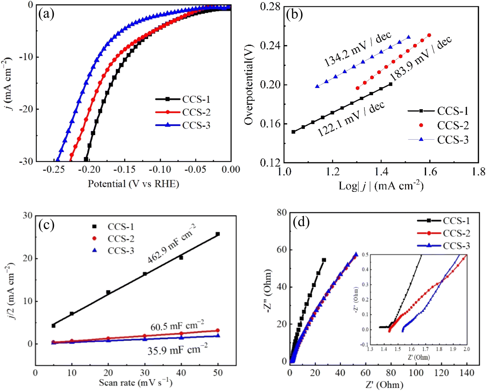
In 1 M KOH solution, LSV is used to study HER catalytic performance of three CuCo2S4/NF catalysts under a scanning rate of 5 mV s−1, as shown in Fig. 5. All polarization curves are iR compensation. CuCo2S4/NF catalyst is used as the working electrode in the three-electrode system. Fig. 5(a) shows the polarization curves of three CuCo2S4/NF catalysts. When the current density is less than 10 mA cm−2, the overpotentials of CCS-1 and CCS-2 electrodes are almost the same. At 10 mA cm−2, the overpotentials of CCS-1 CCS-2 and CCS-3 electrodes are 147 mV, 161 mV and 187 mV, respectively. When the current density is higher than 10 mA cm−2, the overpotential of CCS-1 is significantly lower than that of CCS-2. At 20 mA cm−2, the overpotentials of CCS-1 CCS-2 and CCS-3 samples are 184 mV, 199 mV and 218 mV, respectively. The overpotential of CCS-1 sample is always the smallest. In addition, the electrochemical kinetics of three CuCo2S4/NF catalysts were studied by Tafel slope, as shown in Fig. 5(b). The Tafel slope of CCS-2 sample is the highest, which is 183.9 mV dec−1. The Tafel slope of CCS-1 is much lower than that of CCS-2. The Tafel slope of CCS-1 sample is the lowest, and the corresponding value is 122.1 mV dec−1. Smaller Tafel slope is the result of more catalytic active sites leading to faster electrochemical reaction kinetics.61 As shown in Fig. 3, the hexagonal nanosheet structure provides more catalytic active sites for CCS-1 samples, leading to faster electrochemical reaction of CCS-1 samples and thus better HER catalytic activity. Therefore, the hexagonal nanosheet structure is more favorable to the HER process. Fig. 5(c) are the double-layer capacitance (Cdl) curves according to the CV curves of three CuCo2S4/NF catalysts calculated in Fig. 4. Cdl values reflects the ECSA values of three CuCo2S4/NF catalysts. It can be observed that the Cdl values of CCS-1, CCS-2 and CCS-3 samples are 462.9 mF cm−2, 60.5 mF cm−2 and 35.9 mF cm−2, respectively. The Cdl value of CCS-1 sample was the highest, which reflected that CCS-1 sample had the most catalytic active sites. Fig. 5(d) illustrates the EIS curves of three CuCo2S4/NF catalysts. The catalytic activity of the three CuCo2S4/NF catalysts is influenced by electrochemical charge transfer kinetics and thus can be analyzed by EIS curves. The slope of CCS-1 sample in the low-frequency range is the largest among the three CuCo2S4/NF catalysts, while the radius in the high-frequency one is the smallest among the three, indicating that CCS-1 sample has the fastest charge transfer rate, which contributes to the improvement of electrochemical reaction kinetics and HER catalytic activity, corresponding to the previous results.62
 | ||
| Fig. 5 HER performances of CuCo2S4/NF catalyst with different urea ratios: (a) LSV polarization curves, (b) Tafel curves, (c) double layer capacitance curves, (d) EIS curves. | ||
The long-term stability test is another important technique for evaluating the catalyst performance. The stability of three CuCo2S4/NF catalysts is tested by chronoamperometry at a scanning rate of 10 mV s−1 with the fixed voltage η = 0.6 V for 14 h, as shown in Fig. 6. Because of hydrogen adhering to CuCo2S4/NF catalyst within HER process, the curves fluctuate in different degrees. From Fig. 6(a) that the electric current density generated by CCS-1 sample is the maximum at the initial stage of the reaction, which also confirms the excellent catalytic activity of HER of the previous CCS-1 sample. After the reaction time reached 2 h, the current density of CCS-1 samples began to decrease. After the reaction time reached 8 h, the decrease degree declines. The current density of CCS-2 is essentially the same for 14 h. The current density of CCS-3 samples also decreased from 8 h. Therefore, CCS-2 samples with banded nanosheet structure have good stability, which can be attributed to cross-banded nanosheets providing structural advantage with sufficient reactions. Fig. 6(b) demonstrates the HER performance of the three CuCo2S4/NF catalysts degrades after 14 h.
 | ||
| Fig. 6 Stability test curves of CuCo2S4/NF catalyst with different urea ratios: (a) long-term stability curves, (b) LSV polarization curves after long-term stability test. | ||
Fig. 7 shows the elemental composition of three CuCo2S4/NF catalysts after 14 h stability test. The distribution of Ni, Cu, Co and S elements can be clearly seen from the EDS spectra, indicating that after 14 h HER process, the composition of the three CuCo2S4/NF catalysts did not change significantly, and they are still evenly distributed on the NF substrate.
 | ||
| Fig. 7 SEM and EDS images of CuCo2S4/NF catalysts with different urea ratios (a and b) CCS-1, (c and d) CCS-2, (e and f) CCS-3. | ||
3.2 Effect of NH4F on preparation of CuCo2S4/NF catalyst and electrocatalytic hydrogen evolution performance
As shown in Fig. 8, CuCo2S4 with different ratios of urea and NH4F were prepared by hydrothermal method and calcination. Firstly, CuCo2O4 nanowire was synthesized by hydrothermal method on nickel foam and calcined in air. And then CuCO2O4 was sulfurized by hydrothermal method to obtain CuCo2S4. | ||
| Fig. 8 Schematic illustration of the synthesis of CuCo2O4/NF nanowires with different urea and NH4F ratios. | ||
Fig. 9(a) shows the XRD patterns of CuCo2S4/NF catalysts prepared with different NH4F ratios. The diffraction peaks can be observed at 2θ values of 16.131°, 26.586°, 31.271°, 37.966°, 46.993°, 49.989°, 54.793°, 57.439°, 61.889°, 64.426°, 68.594°, 77.323° and 81.170°. These diffraction peaks correspond to the (022), (113), (004), (224), (115), (044), (026), (137) and (157) crystal planes of CuCo2S4 (JCPDS no. 42-1450), respectively. There is no obvious diffraction peak except for three strong diffraction peaks at 44.40°, 51.76° and 76.26°. From Fig. 9(a) and (b), we conclude that the material is completely converted from oxide to sulfide.
 | ||
| Fig. 9 (a) XRD patterns of CuCo2S4/NF catalyst with different NH4F ratios. (b) XRD patterns of CuCo2O4/NF catalyst with different NH4F ratios. | ||
Fig. 10 shows the SEM images of three CuCo2S4/NF catalysts with fixed urea ratio of 2 mmol and different NH4F ratios. Fig. 10(a) and (b) are SEM images of CuCo2S4/NF catalyst with NH4F ratio of 2 mmol. The morphology of CCNS-1 sample is a complete hexagonal nanosheet structure. Fig. 10(c) and (d) are SEM images of CuCo2S4/NF catalyst with ammonia fluoride ratio of 4 mmol. The morphology of CCNS-2 sample shows layered hexagonal nanosheet structure. Fig. 10(e) and (f) are SEM images of CuCo2S4/NF catalyst with NH4F ratio of 8 mmol. The morphology of CCNS-3 sample exhibits interwoven nanowire structure.
 | ||
| Fig. 10 SEM images of CuCo2S4/NF catalyst with different NH4F ratios: (a and b) SEM images of CCNS-1 at low and high magnification, (c and d) SEM images of CCNS-2 at low and high magnification, (e and f) SEM images of CCNS-3 at low and high magnification. | ||
The (Transmission Electron Microscope) TEM test of CCNS-3 was performed to further understand the microstructure of the catalyst. Fig. 11(a) displays that the CCNS-3 sample exhibits nanowires structure, which corresponds to the SEM images in Fig. 10(e) and (f). It can be seen from HRTEM in Fig. 11(b) that the lattice fringes are 0.2862 nm and 0.2328 nm which correspond to the (113) and (004) crystal planes, respectively.
 | ||
| Fig. 11 TEM images of CCNS-3: (a) TEM image, (b) HRTEM image. | ||
In order to obtain the specific information about chemical composition and state of as-prepared materials, the CCNS-3 samples were characterized by XPS, and the results are shown in Fig. 12. Fig. 12(a) is the survey XPS spectrum of CuCo2S4/NF catalyst, showing the presence of Cu, Co and S. Fig. 12(b) shows the Cu 2p XPS, in which Cu 2p3/2 and Cu 2p1/2 are two spin orbits. The two peaks of the binding energy of 932.5 eV and 952.6 eV correspond to Cu+. The two peaks at 933.8 eV and 954.8 eV correspond to Cu2+. Two satellite peaks at 942.3 eV and 962.8 eV also indicate the presence of Cu2+.63 It can be seen from Fig. 12(c) that the Co 2p XPS contains two spin orbits, Co 2p3/2 and Co 2p1/2. The two significant peaks of binding energy at 781.4 eV and 797.1 eV are Co2+, and the peaks at 778.9 eV and 793.2 eV are due to the presence of Co3+. In addition to the main peak, two different satellite peaks can be found at 786.4 eV and 802.7 eV.64 Fig. 12(d) demonstrates that in S 2p XPS, the two peaks at 162.6 eV and 163.9 eV point to S 2p3/2 and S 2p1/2, respectively. And a satellite peak at 168.5 eV can be observed.65
 | ||
| Fig. 12 XPS images of CCNS-3: (a) Survey XPS, (b) Cu 2p XPS, (c) Co 2p XPS, (d) S 2p XPS. | ||
CV measurements were used to study three CuCo2S4/NF catalysts at varied scanning rates in the non-Faraday region, and the results are shown in Fig. 13. The CV integral area of CCNS-3 sample with nanowire structure is the largest, indicating that CCNS-3 sample has the most catalytic active sites in the whole HER catalytic reaction. Compared with Fig. 4, it was found that the electrochemical performance of CuCo2S4/NF catalyst decreased with an increment of urea ratio under the single effect of urea. However, the electrochemical performance of CuCo2S4/NF can be enhanced with the rise of NH4F ratio under the synergistic action of NH4F and urea.
 | ||
| Fig. 13 CV curves of CuCo2S4/NF catalyst with different NH4F ratios: (a) CCNS-1, (b) CCNS-2, (c) CCNS-3. | ||
Fig. 14(a) shows the polarization curves of three CuCo2S4/NF catalysts tested by LSV at a scanning rate of 5 mV s−1 in 1 M KOH solution, and all the polarization curves are iR corrected. When the current density is 10 mA cm−2, the overpotentials of CCNS-1, CCNS-2 and CCNS-3 samples are 261 mV, 231 mV and 226 mV, respectively. At 20 mA cm−2, the overpotential of CCNS-1 is obviously larger than that of CCNS-2 and CCNS-3, while the overpotential of CCNS-2 and CCNS-3 is almost the same. Fig. 14(b) shows the Tafel curves of three CuCo2S4/NF catalysts, reflecting the reaction kinetics of three CuCo2S4/NF catalysts. The Tafel slopes of CCNS-1, CCNS-2 and CCNS-3 samples are 96.2 mV dec−1, 65.3 mV dec−1 and 66.3 mV dec−1, respectively. The Tafel slope of CCNS-1 is significantly higher than that of CCNS-2 and CCNS-3, while the Tafel slope of CCNS-2 and CCNS-3 shows little difference, which can correspond to the results in Fig. 14(a).65,66 Fig. 14(c) shows the double layer capacitance values of three CuCo2S4/NF catalysts. The Cdl value of CCNS-3 is much higher than that of CCNS-1 and CCNS-2. This also corresponds to the CV curves of the three CuCo2S4/NF catalysts in Fig. 13, indicating that there are many catalytic active sites in CCNS-3 sample.67 Fig. 14(d) shows the EIS curves of three CuCo2S4/NF catalysts. CCNS-3 sample has a small radius in the high-frequency region and a large slope in the low-frequency region, indicating that CCNS-3 sample has good charge transfer and ion diffusing ability. According to the SEM images of the three CuCo2S4/NF catalysts in Fig. 10, the CCNS-1 sample with complete hexagonal nanosheet structure may have a relatively compact morphology, and only the surface is involved in HER catalytic reaction process, resulting in poor HER catalytic performance of the CCNS-1 sample. The HER catalytic performance of CCNS-2 sample with layered hexagonal nanosheet structure is better because the gap between layers increases the contact area with the electrolyte. Because of the staggered nanowire structure, the CCNS-3 sample have a larger contact area with the electrolyte. Therefore, it has better HER catalytic performance.
 | ||
| Fig. 14 HER performances of CuCo2S4/NF catalyst with different NH4F ratios: (a) LSV polarization curves, (b) Tafel curves, (c) double layer capacitance curves, (d) EIS curves. | ||
Fig. 15(a) is a long-term stability test of three CuCo2S4/NF catalysts. The current density of CCNS-1 sample is higher at the beginning of the reaction. With the increase of reaction time, the current density of CCNS-1 sample firstly increased and then decreases. The current density reaches the highest at 1.2 h and stabilizes at 8 h. The decrease of current density may be caused by the destruction of the complete hexagonal nanosheet structure. The initial current density of CCNS-2 sample is lower than that of CCNS-1 sample, and the current density firstly increases and then decreases. The current density is the highest at 0.8 h and tends to be stable at 4 h. When the reaction time is extended to 8 h, the current density of CCNS-2 sample decreases again and stabilizes after 10 h, which may be caused by the gradual destruction of the layered hexagonal nanosheet structure in the reaction process. CCNS-3 sample has the lowest initial current density, but is relatively stable. With the increase of reaction time, the current density of CCNS-3 sample shows an increasing trend, which can be attributed to more and more interwoven nanowire structures of CCNS-3 sample. According to Fig. 15(b), after 14 h, the HER performance of CCNS-1 and CCNS-3 samples is improved, while the overpotential of CCNS-2 sample has no change when the current density is 10 mA cm−2.
 | ||
| Fig. 15 Stability test curves of CuCo2S4/NF catalyst with different NH4F ratios: (a) long-term stability curves, (b) LSV polarization curves after long-term stability test. | ||
Fig. 16 shows EDS images of three CuCo2S4/NF catalysts. The three CuCo2S4/NF catalysts all contain Ni, Cu, Co and S elements with uniform distribution, indicating that the three CuCo2S4/NF catalysts completely grow on the NF substrate.
 | ||
| Fig. 16 SEM and EDS images of CuCo2S4/NF catalysts with different NH4F ratios: (a and b) CCNS-1, (c and d) CCNS-2, (e and f) CCNS-3. | ||
4. Conclusion
In summary, several CuCo2S4/NF and CuCo2O4/NF catalysts are successfully prepared by hydrothermal method. The influence of urea and NH4F ratio on the microstructure and HER catalytic activity of CuCo2S4/NF catalyst has been discussed in detail. When urea is a single variable, the electrochemical performance of CuCo2S4/NF catalyst decreases with an increment of urea ratio. At the current density of 10 mA cm−2, the overpotential and Tafel slope of the CCS-1 sample are 147 mV and 126.9 mV dec−1 respectively, which is better than the other two samples. The electrochemical performance of CuCo2S4/NF catalyst is also improved with the increment of NH4F ratio under the synergistic action of NH4F and urea after urea ratio is fixed. At the current density of 10 mA cm−2, the overpotential of CCNS-3 sample is better (η = 226 mV), and the Tafel slope is 66.3 mV dec−1. It indicates that the Tafel slope of CuCo2S4/NF catalyst with urea remains at a high level. However, the Tafel slope of CuCo2S4/NF catalyst with urea and NH4F shows lower Tafel slope thus better catalytic activity. Therefore, this study exhibits the effect of urea and NH4F ratio on CuCo2S4 catalyst, indicating that the appropriate ratio of urea and NH4F can enhance its catalytic performance, which provides references for the future research of HER electrocatalysts.Author contributions
Yifei Di and Xiangsen Meng carried out the experiment and wrote. Rongda Zhao and Jing Li revised the article. Fufa Wu and Jun Xiang provided financial support for this study. All authors reviewed the manuscript.Conflicts of interest
There are no conflicts of interest to declare.Acknowledgements
This work was financially supported by the National Natural Science Foundation of China (NSFC, Grant No. 51702143 and 51971106), the Natural Science Foundation of Liaoning Province (Grant No. 2021-MS-320), the Youth Project of Education Department of Liaoning Province (No. LJKQZ2021145) and Liaoning Distinguished Professor.References
- Z. W. Seh, J. Kibsgaard, C. F. Dickens, I. B. Chorkendorff, J. K. Nørskov and T. F. Jaramillo, Combining theory and experiment in electrocatalysis: Insights into materials design, Science, 2017, 355, 1–14 CrossRef PubMed.
- S. E. Hosseini and M. A. Wahid, Hydrogen production from renewable and sustainable energy resources: Promising green energy carrier for clean development, Renewable Sustainable Energy Rev., 2016, 57, 850–866 CrossRef CAS.
- C. N. Zou, Q. Zhao, G. S. Zhang and B. Xiong, Energy revolution: From a fossil energy era to a new energy era, Nat. Gas Ind., 2016, 3, 1–11 Search PubMed.
- J. Chi and H. M. Yu, Water electrolysis based on renewable energy for hydrogen production, Chin. J. Catal., 2018, 39, 390–394 CrossRef CAS.
- M. Bhattacharya, S. R. Paramati, I. Ozturk and S. Bhattacharya, The effect of renewable energy consumption on economic growth: Evidence from top 38 countries, Appl. Energy, 2016, 162, 733–741 CrossRef.
- L. X. Wang, Y. Li and X. C. Yin, et al., Comparison of three nickel-based carbon composite catalysts for hydrogen evolution reaction in alkaline solution, Int. J. Hydrogen Energy, 2017, 42, 22655–22662 CrossRef CAS.
- Z. S. Wu, L. Huang, H. Liu and H. L. Wang, Element-specific restructuring of anion-and cation-substituted cobalt phosphide nanoparticles under electrochemical water-splitting conditions, ACS Catal., 2019, 9, 2956–2961 CrossRef CAS.
- W. C. Peng, G. X. Zheng, Y. B. Wang, S. Y. Cao, Z. Ji, Y. H. Huan, M. Q. Zou and X. Q. Yan, Zn doped ZIF67-derived porous carbon framework as efficient bifunctional electrocatalyst for water splitting, Int. J. Hydrogen Energy, 2019, 44, 19782–19791 CrossRef CAS.
- Y. H. Deng, C. Ye, B. X. Tao, G. Chen, Q. Zhang, H. Q. Luo and N. B. Li, One-step chemical transformation synthesis of CoS2 nanosheets on carbon cloth as a 3D flexible electrode for water oxidation, J. Power Sources, 2018, 397, 44–51 CrossRef CAS.
- L. S. Peng, X. Q. Zheng, L. Li, L. Zhang, N. Yang, K. Xiong, H. Chen, J. Li and Z. D. Wei, Chimney effect of the interface in metal oxide/metal composite catalysts on the hydrogen evolution reaction, Appl. Catal., B, 2019, 245, 122–129 CrossRef CAS.
- K. Y. Zhu, F. Shi, X. F. Zhu and W. S. Yang, The roles of oxygen vacancies in electrocatalytic oxygen evolution reaction, Nano energy, 2020, 73, 104761 CrossRef CAS.
- S. Sultan, J. N. Tiwari, A. N. Singh, S. Zhumagali, M. Ha, C. W. Myung, P. Thangavel and K. S. Kim, Single atoms and clusters based nanomaterials for hydrogen evolution, oxygen evolution reactions, and full water splitting, Adv. Energy Mater., 2019, 9, 1900624.1–1900624.48 Search PubMed.
- I. A. Pašti, E. Fako, A. S. Dobrota, N. López, N. V. Skorodumova and S. V. Mentus, Atomically thin metal films on foreign substrates: from lattice mismatch to electrocatalytic activity, ACS Catal., 2019, 9, 3467–3481 CrossRef.
- J. Zhu, L. S. Hu, P. X. Zhao, L. Y. S. Lee and K. Y. Wong, Recent advances in electrocatalytic hydrogen evolution using nanoparticles, Chem. Rev., 2020, 120, 851–918 CrossRef CAS PubMed.
- B. You and Y. Sun, Innovative strategies for electrocatalytic water splitting, Acc. Chem. Res., 2018, 51, 1571–1580 CrossRef CAS PubMed.
- J. Y. Zhang, Y. C. Liu, C. Q. Sun, P. X. Xi, S. L. Peng, D. Q. Gao and D. S. Xue, Accelerated hydrogen evolution reaction in CoS2 by transition-metal doping, ACS Energy Lett., 2018, 3, 779–786 CrossRef CAS.
- X. J. Liu, J. R. Yu, H. H. Song, P. F. Song, R. M. Wang and Y. B. Xiong, Nitrogen and sulfur-codoped porous carbon derived from a BSA/ionic liquid polymer complex: Multifunctional electrode materials for water splitting and supercapacitors, RSC Adv., 2019, 9, 5189–5196 RSC.
- X. S. Wang, Y. H. Zhu, A. Vasileff, Y. Jiao, S. M. Chen, L. Song, B. Zheng, Y. Zheng and S. Z. Qiao, Strain effect in bimetallic electrocatalysts in the hydrogen evolution reaction, ACS Energy Lett., 2018, 3, 1198–1204 CrossRef CAS.
- M. I. Jamesh and X. M. Sun, Recent progress on earth abundant electrocatalysts for oxygen evolution reaction (OER) in alkaline medium to achieve efficient water splitting–a review, J. Power Sources, 2018, 400, 31–68 CrossRef CAS.
- H. Y. Jin, C. X. Guo, X. Liu, J. L. Liu, A. Vasileff, Y. Jiao, Y. Zheng and S. Z. Qiao, Emerging Two-Dimensional Nanomaterials for Electrocatalysis, Chem. Rev., 2018, 118, 6337–6408 CrossRef CAS PubMed.
- W. D. Yang, R. D. Zhao, J. Xiang, S. Loy, Y. F. Di, J. Li, M. T. Li, D. M. Ma and F. F. Wu, 3D hierarchical ZnCo2S4@Ni(OH)2 nanowire arrays with excellent flexible energy storage and electrocatalytic performance, J. Colloid Interface Sci., 2022, 626, 866–878 CrossRef CAS PubMed.
- R. D. Zhao, D. Cui, J. Q. Dai, J. Xiang and F. F. Wu, Morphology Controllable NiCo2O4 Nanostructure for Excellent Energy Storage Device and Overall Water Splitting, Sustainable Mater. Technol., 2020, 24, e00151 CrossRef CAS.
- D. Cui, R. D. Zhao, J. Q. Dai, J. Xiang and F. F. Wu, A hybrid NiCo2O4@NiMoO4 structure for overall water splitting and excellent hybrid energy storage, Dalton Trans., 2020, 49, 9668–9679 RSC.
- S. Anantharaj, K. Karthick, M. Venkatesh, T. V. S. V. Simha, A. S. Salunke, L. Ma, H. Liang and S. Kundu, Enhancing electrocatalytic total water splitting at few layer Pt-NiFe layered double hydroxide interfaces, Nano Energy, 2017, 39, 30–43 CrossRef CAS.
- S. Dou, X. Wang and S. Y. Wang, Rational Design of Transition Metal-Based Materials for Highly Efficient Electrocatalysis, Small Methods, 2019, 3, 1800211 CrossRef.
- C. M. Pedersen, M. Escudero-Escribano, A. Velazquez-Palenzuela, L. H. Christensen, I. Chorkendorff and I. E. L. Sgephens, Benchmarking Pt-based electrocatalysts for low temperature fuel cell reactions with the rotating disk electrode: oxygen reduction and hydrogen oxidation in the presence of CO, Electrochim. Acta, 2015, 179, 647–657 CrossRef CAS.
- Y. Nie, L. Li and Z. D. Wei, Recent advancements in Pt and Pt-free catalysts for oxygen reduction reaction, Chem. Soc. Rev., 2015, 44, 2168–2201 RSC.
- C. Tang, R. Zhang, W. B. Lu, L. B. He, X. E. Jiang, A. M. Asiri and X. P. Sun, Fe-doped CoP nanoarray: a monolithic multifunctional catalyst for highly efficient hydrogen generation, Adv. Mater., 2017, 29, 1602441 CrossRef PubMed.
- W. D. Yang, R. D. Zhao, F. Y. Guo, J. Xiang, S. Loy, L. Liu, J. Y. Dai and F. F. Wu, Interface engineering of hybrid ZnCo2O4@Ni2.5Mo6S6.7 structures for flexible energy storage and alkaline water splitting, Chem. Eng. J., 2023, 454, 140458 CrossRef CAS.
- W. D. Yang, J. Xiang, R. D. Zhao, S. Loy, M. T. Li, D. M. Ma, J. Li and F. F. Wu, Nanoengineering of ZnCo2O4@CoMoO4 heterogeneous structures for supercapacitor and water splitting applications, Ceram. Int., 2022, 49, 4422–4434 CrossRef.
- A. Eftekhari, Electrocatalysts for hydrogen evolution reaction, Int. J. Hydrogen Energy, 2017, 42, 11053–11077 CrossRef CAS.
- Y. M. Kim, D. H. K. Jackson, D. Lee, M. Choi, T. W. Kim, S. Y. Jeong, H. J. Chae, H. W. Kim, N. Park, H. J. Chang, T. F. Kuech and H. J. Kim, In Situ Electrochemical Activation of Atomic Layer Deposition Coated MoS2 Basal Planes for Efficient Hydrogen Evolution Reaction, Adv. Funct. Mater., 2017, 27, 1701825 CrossRef.
- M. Ledendecker, H. Schlott, M. Antonietti, B. Meyer and M. Shalom, Experimental and Theoretical Assessment of Ni-Based Binary Compounds for the Hydrogen Evolution Reaction, Adv. Energy Mater., 2017, 7, 1601735.1–1601735.7 Search PubMed.
- H. J. Yin, S. L. Zhao, K. Zhao, A. Muqsit, H. J. Tang, L. Chang, H. J. Zhao, Y. Gao and Z. Y. Tang, Ultrathin platinum nanowires grown on single-layered nickel hydroxide with high hydrogen evolution activity, Nat. Commun., 2015, 6, 6430.1–6430.8 Search PubMed.
- Z. Qiu, C. W. Tai, G. A. Niklasson and T. Edvinsson, Direct observation of active catalyst surface phases and the effect of dynamic self-optimization in NiFe-layered double hydroxides for alkaline water splitting, Energy Environ. Sci., 2019, 12, 572–581 RSC.
- B. Mohanty, M. Ghorbani-Asl, S. Kretschmer, A. Ghosh, P. Guha, S. K. Panda, B. Jena, A. V. Krasheninnikov and B. K. Jena, MoS2 quantum dots as efficient catalyst materials for the oxygen evolution reaction, ACS Catal., 2018, 8, 1683–1689 CrossRef CAS.
- K. Maslana, K. Wenelska, M. Biegun and E. Mijowska, High catalytic performance of tungsten disulphide rodes in oxygen evolution reactions in alkaline solutions, Appl. Catal., B, 2020, 266, 118575 CrossRef CAS.
- X. Q. Du, H. Su and X. S. Zhang, 3D hierarchical Co3O4@Co3S4 nanoarrays as anode and cathode materials for oxygen evolution reaction and hydrogen evolution reaction, Dalton Trans., 2018, 47, 16305–16312 RSC.
- X. Q. Du, P. X. Che, Y. H. Wang, C. C. Yuan and X. S. Zhang, Ni3S2@Co(OH)2 heterostructures grown on Ni foam as an efficient electrocatalyst for water oxidation, Int. J. Hydrogen Energy, 2019, 44, 22955–22961 CrossRef CAS.
- X. X. Zou, Y. Y. Wu, Y. P. Liu, D. P. Liu, W. Li, L. Gu, H. Liu, P. W. Wang, L. Sun and Y. Zhang, In situ generation of bifunctional, efficient Fe-based catalysts from mackinawite iron sulfide for water splitting, Chem, 2018, 4, 1139–1152 CAS.
- V. Vij, S. Sultan, A. M. Harzandi, A. Meena, J. N. Tiwari, W. G. Lee, T. Yoon and K. S. Kim, Nickel-based electrocatalysts for energy-related applications: oxygen reduction, oxygen evolution, and hydrogen evolution reactions, ACS Catal., 2017, 7, 7196–7225 CrossRef CAS.
- L. L. Ji, L. Zhu, J. Y. Wang and Z. F. Chen, Self-supported CuS nanowire array: an efficient hydrogen-evolving electrode in neutral media, Electrochim. Acta, 2017, 252, 516–522 CrossRef CAS.
- T. T. Wang, L. Q. Wu, X. B. Xu, Y. Sun, Y. Q. Wang, W. Zhong and Y. W. Du, An efficient Co3S4/CoP hybrid catalyst for electrocatalytic hydrogen evolution, Sci. Rep., 2017, 7, 11891 CrossRef PubMed.
- X. M. Geng, W. W. Sun, W. Wu, B. Chen, A. Al-Hilo, M. Benamara, H. L. Zhu, F. Watanabe, J. B. Cui and T. P. Chen, Pure and stable metallic phase molybdenum disulfide nanosheets for hydrogen evolution reaction, Nat. Commun., 2016, 7, 10672 CrossRef CAS PubMed.
- S. Y. Ji, T. T. Li, Z. D. Gao, Y. Y. Song and J. J. Xu, Boosting the oxygen evolution reaction performance of CoS2 microspheres by subtle ionic liquid modification, Chem. Commun., 2018, 54, 8765–8768 RSC.
- H. Pan, Metal dichalcogenides monolayers: novel catalysts for electrochemical hydrogen production, Sci. Rep., 2014, 4, 5348 CrossRef CAS PubMed.
- C. W. Lin, M. Natesan, S. Ummartyotin and Y. H. Chang, 3D Flower-like Zn substituted CuCo2O4 spinel catalyst for electrochemical oxygen evolution reaction, J. Electroanal. Chem., 2023, 937, 117406 CrossRef CAS.
- A. Pendashteh, S. E. Moosavifard, M. S. Rahmanifar, Y. Wang, M. F. El-Kady, R. B. Kaner and M. F. Mousavi, Highly ordered mesoporous CuCo2O4 nanowires, a promising solution for high-performance supercapacitors, Chem. Mater., 2015, 27, 3919–3926 CrossRef CAS.
- S. Czioska, J. Y. Wang, X. Teng and Z. F. Chen, Hierarchically structured CuCo2S4 nanowire arrays as efficient bifunctional electrocatalyst for overall water splitting, ACS Sustainable Chem. Eng., 2018, 6, 11877–11883 CrossRef CAS; X. H. Deng and H. Tüysüz, Cobalt-oxide-based materials as water oxidation catalyst: recent progress and challenges, ACS Catal., 2014, 4, 3701–3714 CrossRef.
- S. M. Pawar, B. S. Pawar, P. T. Babar, A. T. Ahmed, H. S. Chavan, Y. Jo, S. Cho, J. Kim, B. Hou, A. I. Inamdar, S. Cha, J. H. Kim, T. G. Kim, H. Kim and H. Im, Nanoporous CuCo2O4 nanosheets as a highly efficient bifunctional electrode for supercapacitors and water oxidation catalysis, Appl. Surf. Sci., 2019, 470, 360–367 CrossRef CAS.
- Y. P. Sun, D. L. Li, J. X. Lu, Y. Y. Zhang, L. Li and J. Liang, Synthesis of Ni-Doped Copper Cobalt Sulfide Nanoparticles and its Enhanced Properties as an Electrocatalyst for Hydrogen Evolution Reaction, Cryst. Res. Technol., 2019, 54, 1800248 CrossRef.
- M. Chauhan, K. P. Reddy, C. S. Gopinath and S. Deka, Copper cobalt sulfide nanosheets realizing a promising electrocatalytic oxygen evolution reaction, ACS Catal., 2017, 7, 5871–5879 CrossRef CAS.
- Z. W. Hao, P. K. Wei, Y. Yang, J. Y. Sun, Y. H. Song, D. G. Guo and L. Liu, Self-assembled CuCo2S4 nanosheets with rich surface Co3+ as efficient electrocatalysts for oxygen evolution reaction, Appl. Surf. Sci., 2021, 536, 147826 CrossRef CAS.
- M. L. Lu, X. Cui, B. Song, H. Z. Ouyang, K. L. Wang and Y. Q. Wang, Studying the effect of CuCo2S4 morphology on the oxygen evolution reaction using a flexible carbon cloth substrate, ChemElectroChem, 2020, 7, 1080–1083 CrossRef CAS.
- A. Serov, N. I. Andersen, A. J. Roy, I. Matanovic and K. Artyushkova, CuCo2O4 ORR/OER bi-functional catalyst: influence of synthetic approach on performance, J. Electrochem. Soc., 2015, 162, F449 CrossRef CAS.
- H. Li, Y. Q. Chen, S. Q. Liu and Q. Liu, Enhancement of hydrothermal synthesis of FDU-12-derived nickel phyllosilicate using double accelerators of ammonium fluoride and urea for CO2 methanation, J. CO2 Util., 2021, 52, 101677 CrossRef CAS.
- D. D. Wei, W. J. Tang and Y. L. Wang, Hairy sphere-like Ni9S8/CuS/Cu2O composites grown on nickel foam as bifunctional electrocatalysts for hydrogen evolution and urea electrooxidation, Int. J. Hydrogen Energy, 2021, 46, 20950–20960 CrossRef CAS.
- N. Sethulakshmi, S. Nellaiappan, P. Pentyala, M. Sharma, S. Irusta, P. A. Deshpande and S. Sharma, Nanocoral CuCo2S4 thiospinels: Oxygen evolution reaction via redox interaction of metal ions, Electrochim. Acta, 2021, 370, 137701 CrossRef CAS.
- W. Tan, S. Q. Xie, J. W. Yang, J. G. Lv, J. F. Yin, C. Zhang, J. Y. Wang, X. Y. Shen, M. Zhao, M. Zhang, G. He and L. Yang, Effect of carbonization temperature on electrocatalytic water splitting of Fe-Co anchored on N-doped porous carbon, J. Solid State Chem., 2021, 302, 122435 CrossRef CAS.
- C. C. L. McCrory, S. Jung, J. C. Peters and T. F. Jaramillo, Benchmarking heterogeneous electrocatalysts for the oxygen evolution reaction, J. Am. Chem. Soc., 2013, 135, 16977–16987 CrossRef CAS PubMed.
- M. Hassan, Y. Slimani, M. A. Gondal, M. J. S. Mohamed, S. Güner, M. A. Almessiere, A. M. Surrati, A. Baykal, S. Trukhanov and A. Trukhanov, Structural parameters, energy states and magnetic properties of the novel Se-doped NiFe2O4 ferrites as highly efficient electrocatalysts for HER, Ceram. Int., 2022, 48, 24866–24876 CrossRef CAS.
- P. Liu, J. Y. Yan, J. X. Mao, J. W. Li, D. X. Liang and W. B. Song, In-plane intergrowth CoS2/MoS2 nanosheets: Binary metal–organic framework evolution and efficient alkaline HER electrocatalysis, J. Mater. Chem. A, 2020, 8, 11435–11441 RSC.
- I. Y. Y. Bu and R. Huang, Fabrication of CuO-decorated reduced graphene oxide nanosheets for supercapacitor applications, Ceram. Int., 2017, 43, 45–50 CrossRef CAS.
- H. Q. Liu, D. P. Zhao, Y. Liu, P. F. Hu, X. Wu and H. Xia, Boosting energy storage and electrocatalytic performances by synergizing CoMoO4@ MoZn22 core-shell structures, Chem. Eng. J., 2019, 373, 485–492 CrossRef CAS.
- T. Wang, W. B. Ma, Y. X. Zhang, J. D. Guo, T. T. Li, S. H. Wang and D. A. Yang, Construction of CoMoO4@Ni3S2 core-shell heterostructures nanorod arrays for high-performance supercapacitors, J. Energy Storage, 2021, 35, 102319 CrossRef.
- J. Liu, J. S. Wang, B. Zhang, Y. J. Ruan, L. Lv, X. Ji, K. Xu, L. Miao and J. J. Jiang, Hierarchical NiCo2S4@ NiFe LDH heterostructures supported on nickel foam for enhanced overall-water-splitting activity, ACS Appl. Mater. Interfaces, 2017, 9, 15364–15372 CrossRef CAS PubMed.
- X. X. Wu, Y. W. Yang, T. Zhang, B. K. Wang, H. J. Xu, X. B. Yan and Y. Tang, CeOx-Decorated Hierarchical NiCo2S4 Hollow Nanotubes Arrays for Enhanced Oxygen Evolution Reaction Electrocatalysis, ACS Appl. Mater. Interfaces, 2019, 11, 39841–39847 CrossRef CAS PubMed.
| This journal is © The Royal Society of Chemistry 2023 |