 Open Access Article
Dip-coated carbon nanotube surface deposits as stable, effective response enhancers in pencil lead electrode voltammetry†
Kamonwan Chatree and
Albert Schulte
 *
*
School of Biomolecular Science and Engineering (BSE), Vidyasirimedhi Institute of Science and Technology (VISTEC), Rayong 21210, Thailand. E-mail: albert.s@vistec.ac.th
First published on 7th November 2023
Abstract
Graphitic pencil leads (PLs) are inexpensive writing accessories, readily available in stationery shops. Because the round filaments have high conductivity, they are excellent candidates for sustainable electroanalytical sensor fabrication. Here, we show that dip-coated carbon nanotube (CNT) surface deposits can stably enhance the faradaic redox response of cylindrical pencil lead electrodes (PLEs), with just ten simple sequential immersions of assembled PLEs in an aqueous suspension of CNTs producing significant improvement in their analytical performance. Cyclic (CV) and differential pulse (DPV) voltammetry of ferricyanide with unmodified and CNT-modified PLEs confirmed the reproducibility of the modification procedure and the reliability of the extent of signal amplification, as well as the stability of the response. A series of DPV tests with drugs, an environmental pollutant, an enzyme–substrate redox label and an industrial chemical proved the practical applicability of the proposed CNT-PLEs. Based on their observed properties, PLEs with dip-coated CNT deposits are suggested as cost-effective tools for advanced electroanalysis and as green platforms for enzyme biosensor construction.
1. Introduction
Most common working electrodes (WEs) for voltammetric or amperometric electroanalysis are platinum (Pt), gold (Au) or glassy carbon (GC) disks.1,2 They are easily obtainable from global suppliers of electrochemistry accessories as pen-like electrochemical (EC) tools. Alternatively, potential users may make them ‘in-house’ by sealing purchased noble metal wires or GC rods in a cylindrical glass or durable polymer housing with cured epoxy resins and exposing the conductive assembly tip through a sequence of fine emery paper abrasion and alumina polishing steps. More modern WE choices, on the other hand, are screen-printed Pt, Au or carbon bands or disks on plastic or ceramic carrier plates.3,4Commercial pen-like Pt, Au and GC WEs are quite costly (a few hundred dollars per piece), and the homemade equivalents are not much cheaper since they contain costly Pt, Au or GC filaments. Screen-printed Pt, Au or carbon WEs, which are marketed as reasonably priced disposable items, become a budgetary burden if used on a regular basis in large quantities, but in-house fabrication of screen-printed electrodes is not a realistic option as it would involve special equipment, operated by specialist workers. The strong interest in economical WE options led to the first exploration of stationery pencil leads (PLs) as a cheap, easily obtained and processed material for DIY working electrode fabrication.5–8 PL-based electroanalysis is widely used nowadays, as attested in recent reviews, with uses ranging from environmental, clinical and pharmaceutical testing to food screening.9–14 PL electrodes (PLEs) may be built as embedded disks, like their Pt, Au or GC equivalents, or fabricated with a protruding end that works as a rod-shaped electrode, and several published reports suggest that PLE surface pre-treatment and/or modification with polymers, organic species or nanomaterials enhances their analyte sensitivity and selectivity. Electrochemically activated PLEs detected, for instance, food antioxidants, drugs and neurotransmitters significantly better than their untreated precursors.15–21 Examples of the strategy of chemical surface modification are, on the other hand, the sensitive voltammetric detection of adrenaline, riboflavin, hydrazine, glucose, dopamine, histamine and acetaminophen at PLEs with active poly(erythrosine),22 poly(glycine),23 Se nanoneedle,24 CoMoO4 nanoflake,25 MXene,26 Cu@Pd core–shell nanostructure27 or poly(thionine)/CuO nanoparticle28 deposits, respectively. Moreover, many studies have shown that carbon nanotube (CNT) deposits can improve the quality of PLE-based EC sensing.29 Tested PLE geometries include disk- and rod-shaped versions, with CNT attachment by dip-and-dry, drop-and-dry or electrodeposition procedures and immobilization supported by co-deposition of bonding nanomaterials or synthetic or natural polymers.
Here, we show that ten immersions in suspensions of CNTs in water greatly improve the voltammetry of rodlike PLEs. Below are (1) details of our PLE assembly and CNT modification, (2) results of ferricyanide voltammetry with CNT-free and CNT-modified PLEs, (3) ferricyanide voltammetry-based tests of the redox response reproducibility and stability of CNT-modified PLEs and (4) proof of the applicability of CNT-modified PLEs to the electroanalysis of topical analytes, including the analgesic acetaminophen, the antibiotic chloramphenicol, the anticancer agent doxorubicin, the enzyme–substrate label and environmental pollutant 4-nitrophenol and the antiseptic, bleaching agent and disinfectant hydrogen peroxide (H2O2).
2. Experimental
2.1. Materials
All pencil leads were bought in local stationery shops or acquired from online suppliers, and were used for PLE manufacture as received. Other electrode construction materials were conductive carbon paint (SPI Supplies, West Chester, PA, USA), common heat shrinking tubes, thin copper wire and ordinary room-temperature hardening two-component epoxy glue. Refined single-walled CNTs, used for PLE surface modification, were supplied by Carbon Solutions, Inc. (Riverside, CA, USA). The standard chemicals for aqueous solution preparation were analytical grade products of Sigma-Aldrich (St. Louis, MO, USA). The electrolyte for voltammetric EC PLE tests was 100 mM potassium ferricyanide in ultrapure de-ionized water with 100 mM potassium chloride. Electrochemical impedance spectroscopy (EIS) testing of PLEs was conducted in a solution containing 5 mM K4[Fe(CN)6] and K3[Fe(CN)6] in 0.1 M KCl. PLE-based EC analysis of acetaminophen (APAP) (Acros Organics-Thermo Fisher Scientific Inc., Branchburg, New Jersey, USA), chloramphenicol (CAP) (Bio Basic Canada, Inc., Markham, Ontario, Canada), 4-nitrophenol (4-NP), doxorubicin (DOX) and hydrogen peroxide (H2O2) (all Sigma-Aldrich, St. Louis, MO, USA) was carried out with solutions of the compounds in 100 mM potassium chloride.2.2. Instrumentation
Voltammetry and amperometry with unmodified and modified PLEs were performed with a Reference 600+ potentiostat (Gamry Instruments Inc., Warminster, PA, USA). A platinum (Pt) wire with a coiled end and a silver/silver chloride electrode assembly with 3 M KCl filling (Ag/AgCl/3 M KCl) served as the counter- (CE) and the reference-electrode (RE), respectively. Original Gamry data were converted into graphics using OriginPro (Version 2021b) and Microsoft Excel/PowerPoint and are shown in the Results and discussion section. EIS data acquisition and analysis were under the control of a PalmSens4 potentiostat and its PSTrace 5.5 software. Originally acquired EIS data was displayed as Nyquist plots and the charge transfer resistance (Rct) of the ferri-/ferrocyanide redox at a PLE was extracted from fitted curves, assuming that the electrode/redox system is represented by Randle's circuit model.2.3. PLE fabrication
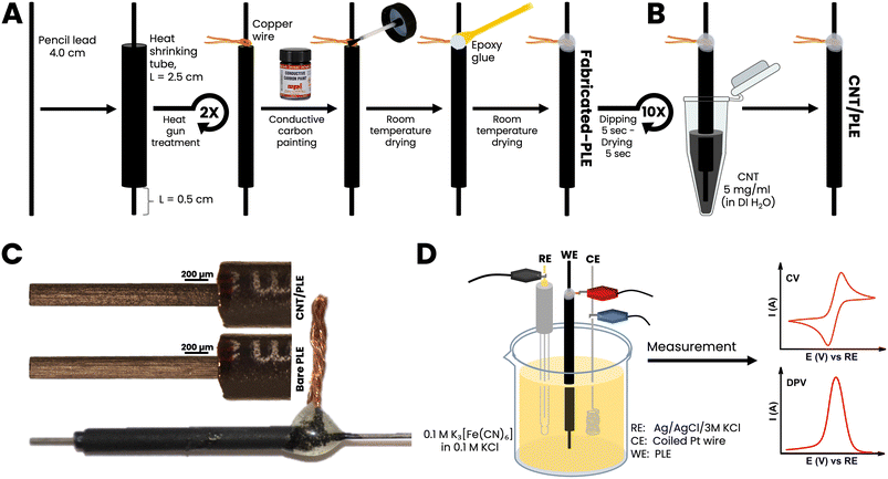
4 cm long pieces of PL were threaded into 2.5 cm long heat-shrinking tubes of slightly larger diameter. Care was taken that 1 cm of the PLs protruded from the plastic tubes at the top and 0.5 cm at the bottom, to serve as the electrical contact point and EC sensor, respectively. The hot air stream from a laboratory heat gun was then used to trigger tube shrinking. This treatment fixed the graphitic stick within a tightly gripping waterproof polymer insulation. A thin copper wire was coiled closely around the upper part of a sealed PL and conductively bonded to the PL with drop-dried carbon paste. The resulting PL–Cu wire-carbon paste spot was strengthened with a covering of epoxy glue. Finished PLEs were used without any pretreatment such as polishing, physical or electrochemical cleaning or surface activation.3. Results and discussion
3.1. Remarks on PLE design and initial performance tests
PLs are mass-fabricated items, obtained by compacting a mixture of graphitic carbon powder and clay into dimensionally stable rods. Manufacturers vary the proportions of graphite and clay to adjust the degree of the hardness of the final product: the more graphite the softer the PL and the more clay the harder. It is important for the application described here that PLs are electrically conductive and cheaply available in ordinary office supply shops, usually with diameters of 0.2–1.0 mm and hardness/softness ratings of 1 to 4H (hard), F or HB (medium), and 1 to 4B (soft). Fig. 1, parts (A) and (B) shows the series of steps that were performed to turn commercial PLs into cylinder-shaped PLEs (Fig. 1(C)). The length and diameter selected were 0.5 cm and 0.5 mm, respectively. The use of thinner graphite sticks or longer protruding portions would have made the sensor tools more fragile and difficult to handle, while the choice of shorter exposed PL sections would have compromised the size of the active electrode area too much. A first set of PLEs was made with 10 PLs of the same brand (Pentel AinSTEIN) and diameter (0.5 mm) but of 4H, 3H, 2H, H, F, HB, B, 2B, 3B and 4B grades. For all unmodified PLs used in this trial the specific graphite rod resistance (Ω cm−1) was measured with a simple multimeter device and converted into conductivity using Ohm's law. Value comparison confirmed that the electron transport through the different PLs was virtually independent of their hardness/softness grade. (Table S1†). As shown in Fig. 1(D), cyclic (CV) or differential pulse (DPV) voltammograms were made for 100 mM ferricyanide in 100 mM KCl for unmodified and CNT-modified versions of the test group to inspect their EC redox response. The resulting ferricyanide CV and DPV duplets are shown in ESI Fig. S1.† It is obvious from the voltammogram compilation that the tool performance was practically unaffected by a change of the grade of the PLs that were embedded in polymer tubes as electrode rods. For neither unmodified (black traces) nor CNT-modified (red traces) PLEs were the ferricyanide CV peak currents and potentials and the ferricyanide DPV maxima much changed by the hardness/softness. However, the sizes of CV and DPV peaks were consistently larger for PLEs that had been dipped 10 times in a CNT suspension, with 5 s-long periods between immersions. Apparently, the simple dip/dry treatment modified the surfaces of PLE with a CNT deposit that then improved the responsiveness in the ferricyanide voltammetric recordings. That 10 repetitions of 5 second immersions in aqueous CNT suspension, with a total exposure time of 50 s, indeed brought about a PL surface change became evident during representative checks of HB versions of the graphite rods by scanning electron microscopy (SEM). At 50× magnification unmodified and treated HB-PLs appeared the same (Fig. 2A(1) and B(1)). In SEM zooms the unmodified PL surface looked rough and, as expected for a graphite-based material, layered micron-sized graphite platelets were noticeable (Fig. 2A(2) and (3)). For HB-PLs that had been dip-and-dry-coated with CNT the flaky silhouettes of the graphite microdomains could not be resolved. Instead, CNT-treated HB-PL surfaces appeared to be thinly covered with the applied CNT coat (Fig. 2B(2) and (3)), which produced the electrochemically verified improvement of the redox of CNT-modified PLEs with ferricyanide, compared to responses of unmodified PLEs.Three each of the hardest (4H), medium (HB) and softest (4B) Pentel AinSTEIN PLEs were modified with CNT by 10-fold repetitions of the dip-and-dry cycle and EIS data were collected for the customized items and their bare versions, too. Compared to their unmodified equivalents, CNT-modified 4H-, HB- and 4B-PLEs showed drastically reduced charge transfer resistances (Fig. S2†) during ferri-/ferrocyanide redox. Obviously, the more effective electron transfer from the dissolved redox species to surface-attached CNT entities on the conductive PL stick is main reason for the better performance of CNT-modified PLEs in the voltammetry trials.
To evaluate the influence of the number of dip/dry cycles on the sensor performance the CNT modification of PLEs was carried out for one PLE model, namely the HB Pentel AinSTEIN PLE, with one, five, ten and twenty iterations of the sequence of 5 second immersions in the aqueous CNT suspension, with 5 second rests in air. The resulting CNT-modified PLEs were carefully inspected by cyclic and differential pulse voltammetry and also with electrochemical impedance spectroscopy (EIS). The results showed that a single dip/dry treatment of an HB-PLE already generated a detectable enhancement of the redox voltammetry (Fig. S3†) and a decrease in the charge transfer resistance (Rct) during ferri-/ferrocyanide redox (Fig. S4†). However, the degree of both improvements reached a maximum with 10 immersion/drying cycles, while doubling to 20 cycles did not further improve electrochemical signaling (Fig. S3 and S4†). A 10-fold dip-and-dry treatment was therefore chosen the standard for all PLE items in the work described below.
Thirty-five different brands of HB-type PLs were on offer from local stationery shops and online sellers, and this availability was a definite advantage of HB-grade PLs, which also offered a good balance of clay and graphite components, which was expected to increase both the responsiveness and the stability of the desired PLEs. All purchased HB-PLs were converted into PLEs with and without CNT and sets of the CVs and DPVs for 100 mM ferricyanide were acquired for the entire collection. A representative example of a CV/DPV ensemble is shown as parts A and B of Fig. 3 while all gathered CV and DPV and recordings are displayed in the ESI Fig. S5 and S6.† Practically all the HB-PLEs fashioned showed improved ferricyanide redox detection performance on dip-coating with CNT, and showed, to greater or lesser extent, increased voltammetric peak currents after ten immersions in an aqueous suspension of graphitic nanotubes. This result is visualized in the bar chart diagram in Fig. 3(C), which displays the gain in the DPV ferricyanide reduction current, ΔIpc, for the 35 HB-PLEs inspected, as induced by the CNT deposit.
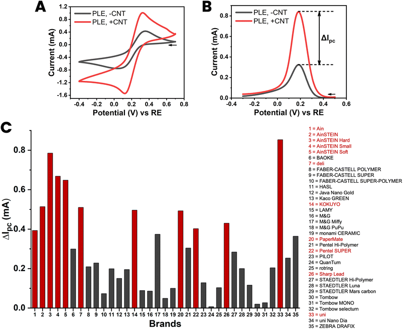 | ||
| Fig. 3 Cyclic (A) and differential pulse (B) voltammograms of 100 mM ferricyanide at a HB-PLE (PL brand: AinSTEIN) without (black) and with (red) CNT modification. (C) A bar chart of the current increase induced by the proposed CNT modification of HB-PLEs, for all 35 PL brands tested. The supporting electrolyte for the measurements was 100 mM KCl, the scan speed for CV acquisition was 50 mV s−1 and the pulse size and time for DPV recordings were 50 mV and 200 ms, respectively. The EC cell was arranged as shown in Fig. 1(D), with a coiled Pt counter-electrode and an Ag/AgCl/3 M KCl reference. | ||
3.2. Reproducibility tests with CNT-modified “HB” PLEs
The reproducibility of the proposed method of CNT modification was assessed for the best 11 HB-PLEs from the test in Section 3.1, explicitly for all those with red bars in Fig. 3(C). For the eleven chosen PLs, 3 PLEs were made from the same purchase batch, and then tested by ferricyanide voltammetry. The libraries of the CVs and DPVs of the trial are shown in ESI Fig. S7 and S8.† Fig. 4 shows the CVs and DPVs of the KOKUYO PLE, chosen as an illustrative case. The reproducibility of PLE fabrication and CNT modification was shown by the superimposability of equivalent CVs and DPVs (Fig. 4(A) and (B)). Fig. 4(C) is a bar chart showing the averaged gain in cathodic DPV current for the 11 members of the PLE sensor set, with the standard deviation of the values expressed as error bars (mean ± SD; n = 3). The DPV response enhancement by CNT modification varied from brand to brand. However, reasonably small standard deviations of the means proved that the signal amplification for all 11 brands was suitably reproducible for electrode replicates made with PLs of the same batch.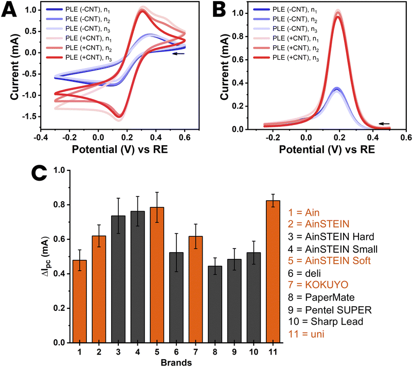 | ||
| Fig. 4 Cyclic (A) and differential pulse (B) voltammograms of 100 mM ferricyanide at a HB-PLE (PL brand: KOKUYO) without (blue) and with (red) CNT modification. The CVs and DPVs from three separate PLEs, prepared with three different PLs from the same purchase batch, are overlaid in the two plots. (C) Bar chart of the current increase, ΔIpc, induced by CNT modification of the HB-PLEs, for all 11 PL brands used in the three-fold reproducibility trial. The supporting electrolyte for the measurements was 100 mM KCl, the scan speed for CV acquisition was 50 mV s−1 and the pulse size and time for DPV recordings were 50 mV and 200 ms, respectively. The EC cell was arranged as shown in Fig. 1(D), with a coiled Pt counter and an Ag/AgCl/3 M KCl reference electrode. | ||
3.3. Durability tests with CNT-modified “HB” PLEs
Five HB-PLEs from the reproducibility test in Section 3.2, explicitly those in Fig. 4(C) with orange bars, were further checked for the durability of their CNT modification, once the nanomaterial was in place. For each durability trial a HB-PLE was first tested by ferricyanide voltammetry, to record the response of the unmodified sensor. CNT deposition was then completed, and electrochemical testing performed immediately (t = 0) and again after minutes, hours and days of storage in stirred water. Libraries of CVs and DPVs from the PLE stability test were acquired at stirring rates of 150, 500 and 1000 rpm. The low magnetic bar rotation speed was a realistic simulation of the experimental conditions during, for instance, standard amperometric experiments. The two higher rates were intended to be a more severe hydrodynamic challenge for the CNTs on the PL surface. An important observation from the trial at 150 rpm was that immersion in a gently stirred solution did not substantially alter the performance of CNT-modified HB-PLEs (Fig. 5(A) and ESI Fig. S9†). The CNT strands, applied as interfacial voltammetric response enhancers in a simple dip-and-dry coating step, were obviously anchored firmly enough that they were not detached to any significant degree. Only hydrodynamic forces far beyond normal conditions and day-long treatment times led to significant decreases in the current response of CNT-treated PLEs through loss of the nanomaterial (Fig. 5(B), (C), ESI Fig. S10 and S11†). PLs are rich in surface-exposed graphite and CNTs are rolled-up graphite sheets. For the proposed CNT-modified HB-PLEs the observed robust CNT fixation is probably due to strong non-covalent affinity between the π electrons of the extended aromatic structures of the nanotubes and graphite platelets. That distinct supramolecular π–π stacking can create stable bonding between CNTs and graphitic surfaces or molecules with aromatic regions was recently discussed in a few topical original articles.30–33 Here the strength of π–π interactions apparently provided a simple strategy for the firm immobilization of CNTs on PLs to enhance their redox performance.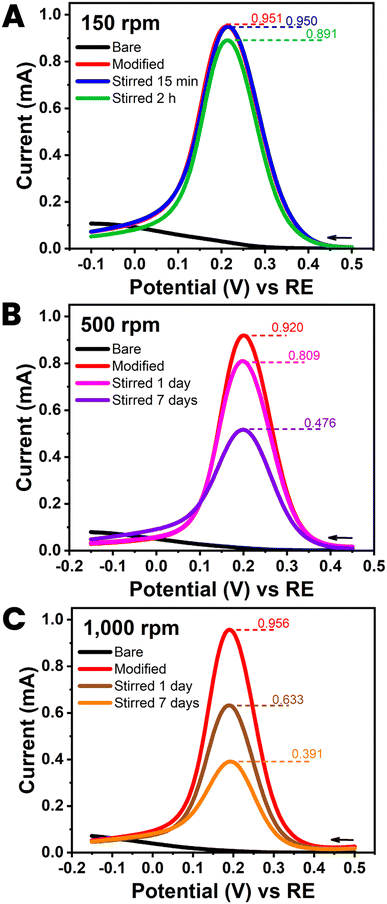 | ||
| Fig. 5 Durability test with a CNT-modified HB pencil lead electrode. Plots (A)–(C) are the 100 mM ferricyanide differential pulse voltammograms (DPVs) obtained at HB-PLEs (PL brand: uni) without (black) and with (red) CNT modification. The three plot sets also include the two DPVs that were acquired after storage of the sensor tools in stirred DI water. Stirring rates were 150 (A), 500 (B) and 1000 (C) rpm. Exposure times were 15 min ((A) blue), 2 hours ((A) green), 1 day ((B) pink; (C) brown) and 7 days ((B) purple; (C) orange). DPV parameters were as for Fig. 3(B). | ||
3.4. Applicability tests with CNT-modified “HB” PLEs
Drugs, metabolic disease biomarkers, fruits, herbs and other food nutrients and contaminants, environmental pollutants and enzyme assay reporter molecules are classic subjects for modern electroanalysis. To validate the improvement that CNT modification of PL surfaces was expected to offer for feasible analyte detection with PLE sensors, electrochemical tests with unmodified and CNT-modified PLEs were performed with five model analytes: three pharmaceuticals (acetaminophen, an analgesic and antipyretic, chloramphenicol, an antibiotic, and doxorubicin, an anticancer agent), one environmental pollutant and routine enzyme assay label (4-nitrophenol) and hydrogen peroxide (H2O2) an industrial commodity, source of toxic radical species in the body, and the detected species in oxidase-based amperometric biosensing.It is clear from the four sets of DPVs in Fig. 6 that modification of the PLE surface with low levels of CNT enhances the quality of both anodic (Fig. 6(A), (B) and (D)) and cathodic (Fig. 6(C)) voltammetry of organic compounds. For all tested models the DPV peak currents were significantly amplified by CNT-modification to levels that are suitable for quantitative detection, e.g. by DPV testing in the standard addition mode. A non-organic analyte for PLE testing was H2O2. This small molecule is a by-product of oxidase-based substrate conversion on platinum or carbon sensors with immobilized oxidases in anodic or cathodic amperometric detection. The best-known example is the glucose oxidase biosensor used by diabetic patients as a home health care device for glucose testing in finger-prick blood samples. Here, we used unmodified and CNT-modified HB-PLEs to measure H2O2 by amperometric recording of anodic current at +600 mV versus RE.
 | ||
| Fig. 6 Applicability test I with a CNT-modified HB PLE (PL brand: KOKUYO), showing DPVs for (A) 250 μM 4-nitrophenol (4-NP), (B) 250 μM acetaminophen (APAP), (C) 250 μM chloramphenicol (CAP) and (D) 250 nM doxorubicin (DOX). Black and blue current traces were taken in analyte-free solutions (blanks) with unmodified and CNT-modified PLEs. Red and green traces are DPV recordings in analyte-containing solutions with unmodified and CNT-modified PLEs, respectively. DPV parameters were as listed in Fig. 3(A). | ||
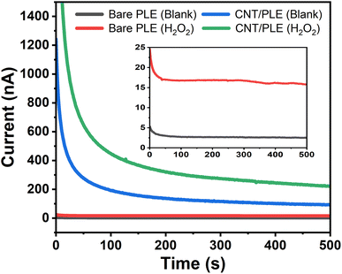
Fig. 7 is a typical example of an assembly of four anodic amperograms that were individually acquired with unmodified and CNT-modified HB-PLEs in the presence and absence of 250 μM H2O2. The fast-declining early phase in the current plots is related to the application of the detection potential and the charge flow that is required to establish the desired +600 mV sensor polarization. Toward the end of the recording the capacitive signal contribution decayed to insignificant levels and the measured current represents the oxidation of the analyte in the test solution, which here is H2O2. For the bare and the CNT-modified HB-PLEs a change from 0 to 250 μM H2O2 increased the sensor current by 15.8 and 222 nA, respectively. This almost fifteenth-fold signal increase was another experimental proof that CNT modification greatly enhances the performance of PLEs in electrochemical detection.
Table S2† compares the design and performance characteristics of the cylindrical CNT-PLEs reported in this work with those of published disk- and cylindrically shaped equivalents. While a CNT drop-casting procedure with solvent evaporation is expected to be more efficient for CNT deposition on a disk PLE than the dip-and-dry process, for the cylindrical PLEs described here showed an equal or even better voltammetry performance and had better EIS charge transfer characteristics. They were also competitive with the cylindrical equivalents with extra polymer nanostructures and/or metal/metal oxide nanoparticles added to the surface modification, and they were superior to the only cylindrical PLE in the table with simple CNT modification. As a novel feature the proposed CNT-PLE sensors thus achieved a substantial improvement in electroanalytical response through a simple and sustainable fabrication procedure.
4. Conclusions
We have introduced a simple and economic tactic for the adaptation of low-cost PLEs with a CNT deposit that markedly enhances their electrochemical redox response as sensors. Performing the nanomaterial surface modification needed only a few immersions of the prefabricated PLEs in a dilute suspension of CNTs in DI water. The observation of reliable voltammetric signal enhancement in tests with thirty-five different pencil leads proved the universal applicability of the proposed modification method, while the reproducibility was confirmed by the small deviations of peak currents from triplicate CV and DPV measurements with identically prepared copies of CNT-PLE prototypes. The response of completed CNT-PLEs was stable over the timescale of standard electrochemical measurements and CNT-PLEs detected a selection of topical analytes considerably better than unmodified precursor PLEs. PLs are cheap and easily obtained, the derived PLEs are easy to make, and their sensitivity-enhancing CNT modification is simple to perform. With these major technical advantages and the confirmed excellent detection capability in mind, our CNT-PLEs are recommended as robust and budget-friendly tools for sustainable electroanalysis. Our own further work will attempt their integration into devices for microfluidic electrochemical sample screening and the proposed CNT-PLEs will be explored as the basis of ‘green’ electrochemical enzyme biosensors.Author contributions
KC: data curation, formal analysis, validation, visualization, writing – review and editing. AS: conceptualization, project administration, funding acquisition, resources, supervision, writing – original draft, writing – review and editing.Conflicts of interest
There are no conflicts to declare.Acknowledgements
The authors thank their institution VISTEC for the general study funding and the M. Eng. fellowship for Kamonwan Chatree. Finanicial support by the Thailand Science Research and Innovation (TSRI), through fundamental grant, fiscal year 2024 is also acknowledged, as is Dr David Apps, Edinburgh Medical School, Edinburgh, Scotland for his dedicated manuscript proofreading.References
- C. B. Braungard, Anal. Methods, 2015, 7, 1249–1260 RSC.
- N. Elgrishi, K. J. Rountree, B. D. McCarthy, E. S. Rountree, T. T. Eisenhart and J. L. Dempsey, J. Chem. Educ., 2018, 95, 197–206 CrossRef CAS.
- A. García-Miranda Ferrari, S. J. Rowley-Neale and C. E. Banks, Talanta Open, 2021, 3, 100032 CrossRef.
- E. Costa-Rama and M. T. Fernández-Abedul, Biosensors, 2021, 11, 51 CrossRef CAS PubMed.
- Md. H. Zahir and S. Ab Ghani, Anal. Chim. Acta, 1999, 354, 351 CrossRef.
- M. Ozsoz, A. Erdem, K. Kerman, D. Ozkan, B. Tugrul, N. Topcuoglu, H. Ekren and M. Taylan, Anal. Chem., 2003, 75, 2181 CrossRef CAS PubMed.
- S. Y. Ly, Y. S. Jung, M. H. Kim, I. K. Han, W. W. Jung and H. S. Kim, Microchim. Acta, 2004, 146, 207 CrossRef CAS.
- D. Demetriades, A. Economou and A. Voulgaropoulos, Anal. Chim. Acta, 2004, 519, 167 CrossRef CAS.
- A.-N. Kawde, N. Baig and M. Sajid, RSC Adv., 2016, 6, 91325 RSC.
- A. Torrinha, C. G. Amorim, M. C. B. S. M. Montenegro and A. N. Araújo, Talanta, 2018, 190, 235 CrossRef CAS PubMed.
- A. Nathani, N. Vishnu and C. S. Sharma, J. Electrochem. Soc., 2020, 167, 037520 CrossRef CAS.
- Annu, S. Sharma, R. Jain and A. N. Raja, J. Electrochem. Soc., 2020, 167, 037501 CrossRef CAS.
- I. G. David, M. Buleandra, D. E. Popa, M. C. Cheregi, V. David, E. E. Iorgulescu and G. O. Tartareanu, Processes, 2022, 10, 472 CrossRef CAS.
- V. N. Ataide, I. V. S. Arantes, L. F. Mendes, D. S. Rocha, T. A. Baldo, W. K. T. Coltro and T. R. L. C. Paixão, J. Electrochem. Soc., 2022, 169, 047524 CrossRef CAS.
- A. Özcan and Y. Sahin, Electroanalysis, 2009, 21, 2363 CrossRef.
- E. Alipour and S. Gasemlou, Anal. Methods, 2012, 4, 2962 RSC.
- A. H. Oghli, E. Alipour and M. Asadzadeh, RSC Adv., 2015, 5, 9674 RSC.
- H. T. Purushothama and Y. A. Nayaka, Sens. Bio-Sens. Res., 2017, 16, 12 CrossRef.
- E. Keskin and A. S. Ertürk, Ionics, 2018, 24, 4043 CrossRef CAS.
- E. Alipour, F. M. Bolali, S. Norouzi and A. Saadatirad, Food Chem., 2022, 375, 131871 CrossRef CAS PubMed.
- S. Srinivas and A. S. Kumar, Biosensors, 2023, 13, 353 CrossRef CAS PubMed.
- S. D. Sukanya, B. E. K. Swamy, J. K. Shashikumara, S. C. Sharma and S. A. Hariprasad, Sci. Rep., 2023, 13, 4523 CrossRef CAS PubMed.
- N. Sedhu, J. J. Kumar, P. Sivaguru and V. Raj, J. Electroanal. Chem., 2023, 928, 117037 CrossRef CAS.
- S. Ishtiaq, M. Sohail, S. Rasul, A. W. Zia, L. Siller, G. A. Chotana, M. Sharif and A. Nafady, ACS Appl. Nano Mater., 2022, 5, 14336 CrossRef CAS.
- N. Priyanga, K. Sasikumar, A. S. Raja, M. Pannipara, A. G. Al-Sehemi, R. J. V. Michael, M. P. Kumar, A. T. Alphonsa and G. G. Kumar, Microchim. Acta, 2022, 189, 200 CrossRef CAS PubMed.
- U. Amara, M. T. Mehran, B. Sarfaraz, K. Mahmood, A. Hayat, M. Nasir, S. Riaz and M. H. Nawaz, Microchim. Acta, 2021, 188, 230 CrossRef CAS PubMed.
- R. K. R. Gajjala, B. Naveen and P. S. Kumar, ACS Appl. Nano Mater., 2021, 4, 5047 CrossRef CAS.
- B. Dalkiran and C. M. A. Brett, Anal. Bioanal. Chem., 2021, 413, 1149 CrossRef CAS PubMed.
- M. R. Akanda, M. Sohail, M. A. Aziz and A.-N. Kawde, Electroanalysis, 2016, 28, 408 CrossRef CAS.
- R. Haddad, S. Cosnier, A. Maaref and M. Holzinger, Analyst, 2009, 134, 2412 RSC.
- A. Le Goff, F. Moggia, N. Debou, P. Jegou, V. Artero, M. Fontecave, B. Jousselme and S. Palacin, J. Electroanal. Chem., 2010, 641, 57 CrossRef CAS.
- V. A. Karachevtsev, A. M. Plokhotnichenko, M. V. Karachevtsev and V. S. Leontiev, Carbon, 2010, 48, 3682 CrossRef CAS.
- S. Zanarini, M. Vinante, L. Pasquaedini, A. Sanginario, M. Giorcelli, S. Bianco, C. Gerbaldi, J. R. Nair, L. Lunelli, L. Vanzetti, F. Paolucci, M. Marcaccio, L. Prodi, A. Tagliaferro, C. Pederzolli, D. Demarchi and P. Civera, Electrochim. Acta, 2011, 56, 9269 CrossRef CAS.
Footnote |
| † Electronic supplementary information (ESI) available. See DOI: https://doi.org/10.1039/d3ra05688k |
| This journal is © The Royal Society of Chemistry 2023 |

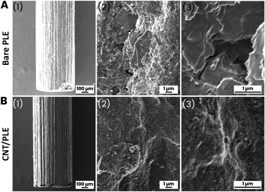
![[thin space (1/6-em)]](https://www.rsc.org/images/entities/char_2009.gif) 000×) resolution scanning electron microscopy images of (A) an unmodified pencil lead (PL brand: Pentel AinSTEIN; grade: HB; diameter: 0.5 mm) and (B) a pencil lead of the same type as in (A) but after ten immersions in a weak CNT suspension, with 5 s long rests between immersions.
000×) resolution scanning electron microscopy images of (A) an unmodified pencil lead (PL brand: Pentel AinSTEIN; grade: HB; diameter: 0.5 mm) and (B) a pencil lead of the same type as in (A) but after ten immersions in a weak CNT suspension, with 5 s long rests between immersions.