 Open Access Article
Facile one-pot synthesis of biomass-derived activated carbon as an interlayer material for a BAC/PE/Al2O3 dual coated separator in Li–S batteries†
Seongho Jo‡
b,
Jeong-Won Hong‡cf,
Toshiyuki Mommad,
Yiseul Parkf,
Junyoung Heoce,
Jun-Woo Park*ce and
Seongki Ahn *a
*a
aDepartment of Chemical Engineering, Hankyong National University, 27, Jungangro, Anseong-si, Gyeonggi-do, Republic of Korea. E-mail: skahn@hknu.ac.kr
bDepartment of New Energy and Mining Engineering, Sangji University, 83 Sangjidae-gil, Wonju-si, Gangwon-do, Republic of Korea
cBattery Research Division, Korea Electrotechnology Research Institute (KERI), 12, Jeongiui-gil, Seongsan-gu, Chawon-si, Gyeongsangnam-do, Republic of Korea. E-mail: parkjw@keri.re.kr
dGraduate School of Advanced Science and Engineering, Waseda University, Okubo, Shinjuku-ku, Tokyo, 169-8555, Japan
eDepartment of Electro-Functionality Materials Engineering, University of Science and Technology (UST), 217, Gajeong-ro, Yuseong-gu, Daejeon, Republic of Korea
fDepartment of Chemical Engineering, Pukyong National University, 45, Yongso-ro, Nam-gu, Busan, Republic of Korea
First published on 12th September 2023
Abstract
Lithium–sulfur batteries (LSB) are an attractive alternative electrochemical energy storage device compared to conventional lithium-ion batteries due to their higher theoretical capacity and energy density. Despite these advantages, it is still difficult to commercialize LSB because of poor electrochemical performance caused by the dissolution of soluble lithium polysulfides (LiPS). To solve these critical issues, a multi-functional separator was prepared using biomass-derived activated carbon (BAC) and a ceramic layer on the polyethylene (PE) separator. For this purpose, BAC was synthesized by a facile one-pot synthesis method by a specifically designed furnace using various forms of milk waste. The multi-functional separator suppresses the effect of LiPS dissolution and increases the Li+ diffusion kinetics. BAC was able to absorb the LiPS shuttle, as confirmed by UV-vis measurements and X-ray photoelectron spectroscopy (XPS). LSB cells assembled using this multi-functional separator show a higher discharge capacity of 1092.5 mA h g−1 at 0.1 C-rate, while commercial PE separators deliver a specific capacity of 811.8 mA h g−1. These novel separators were also able to suppress lithium dendrites during cycling. This work offers a novel and simple approach for streamlining the synthesis process of BAC and applying it to LSB, aiding in the development of sustainable energy sources.
Introduction
The development of electrochemical energy storage devices with high volumetric/gravimetric energy and power density is important because of the rapid development of large-scale battery industries such as electric vehicles and energy storage systems.1–5 However, commercial Li-ion batteries (LIB) which use insertion-type cathode materials such as LiCoO2, LiFePO4, and LiNixMnxCoxO2 are approaching the energy/power density limit due to their low specific capacity (<200 mA h g−1).6–9 For this reason, electrochemical energy storage devices such as Li–S,10–16 Li–air,17–19 and Li–metal batteries20–22 are considered attractive alternatives as next-generation rechargeable batteries. Among these, lithium–sulfur batteries (LSB) are a potential candidate because of their high energy density compared to commercial LIB. Sulfur and lithium are used as cathode and anode materials, respectively, in LSB. Sulfur is advantageous as a cathode material because of its abundance, low cost (<30 $ per ton), environmental friendliness, high theoretical capacity (1675 mA h g−1), and approximately 3–5 times higher gravimetric energy density (2600 W h kg−1) than commercial LIB.23–28 Despite the materials and electrochemical advantages of a sulfur cathode, commercialization of LSB is limited owing to several critical issues like (1) the low utilization of active material in sulfur cathodes due to low electrical conductivity of elemental S, (2) dissolution of lithium polysulfide (LiPS) from cathode to a liquid electrolyte leading to the shuttle effect, (3) volume exchange of elemental S (∼80%), and (4) safety issues in Li dendrite growth during the charge and discharge process. To address these limitations, several studies have focused on various solutions, including immobilization of LiPS using porous cathode additives,29–31 lithium penetrated polymer layer on the cathode,32–34 multi-functional separators,35–37 and electrolyte additives38–40 for better formation of surface electrolyte interface on the surface of Li anodes. Among these, multi-functional separators, which function by suppressing the LiPS and Li dendrite growth during charge and discharge cycling, are the most simple way to enhance the electrochemical performance of LSB.41–43 The carbon layer coated on the commercial separator acts as a barrier which suppresses the LiPS dissolution from cathode to anode and enhances the S transformation kinetics. Notably, it can improve electron mobility in sulfur cathodes, resulting in an enhancement of the electrochemical performance of LSB. To synthesize the multi-functional separator for LSB, numerous organic and inorganic materials have been studied, such as porous carbon,44–47 polymeric materials,48–50 spherical or linear ceramic materials,51–53 and metallic material-modified separators.54–56 These materials can play a role in not only immobilizing and suppressing materials of LiPS through physical and chemical reactions but also blocking the Li dendrite growth. Biomass-derived activated carbon (BAC) as a coating layer on the commercial separator is highly versatile owing to abundant carbon resources. Furthermore, its application aids in sustainable development as it is an eco-friendly material. A variety of animal and plant resources such as eggshells, crustacean shells, animal bones, bamboo, rice husk, coconut shell, and other raw materials have been used as carbon precursors.57–59In this study, milk waste (MW), including raw milk, expired milk, and expired powdered milk, was used as a carbon precursor. BAC powder was successfully synthesized by a one-pot synthesis process. A multi-functional separator with a dual-side coating of BAC and Al2O3 was made on the commercial polyethylene (PE) separator. At the first cycle (0.1 C-rate), the coin-cell assembled using the BAC/PE/Al2O3 separator delivers a high reversible capacity of 1087 mA h g−1 with a favorable coulombic efficiency (CE) of 83.9%, while the cell with a bare PE separator shows a low discharge capacity of 810 mA h g−1 and a CE of 68.6%. The suppressing ability of BAC/PE/Al2O3 separator and immobilization effect of BAC were investigated by a penetration test with 0.1 M Li2S6 solution in DME solution using H-type cell, UV-vis measurement, and X-ray photoelectron spectroscopy (XPS). This work sheds light on the possibility of a simple method for synthesis of biomass porous carbon for the commercialization of LSB.
Experimental
Synthesis of BAC
MW, including raw milk, expired milk, and expired powdered milk, collected from local farms and markets, was used as a carbon resource. To fabricate the dried powder, MW was mixed and dried at 80 °C for 24 h in a circulating oven. The pyrosis and activation processes were carried out using a tube furnace. For the facile synthesis of BAC, a specially programmed tube furnace was used using N2 and CO2 gas. The carbonization was carried out in the tube furnace at 600 °C with N2 for 30 min at a heating rate of 10 °C min−1. After the carbonization process, the gas injected into the tube was changed from N2 to CO2 gas for 30 min to change the atmosphere. Next, the physical CO2 activation was conducted at 700, 800, and 900 °C for 3 min. The CO2-activated BAC samples were ground with an agate mortar and pestle for 30 min.Preparation of multi-functional separator
A multi-functional separator was prepared using 0.2 g of polyvinylidene fluoride (PVDF, Alfa Aesar, USA) and 2.0 g of N-methyl-2-pyrrolidone (NMP, Junsei Chemical, Japan), PVDF and mixed using an agate mortar and pestle for 15 min. 0.8 g of BAC and 0.3 g of NMP were added to the above mixture for the mixing process. The mixed slurry was coated on the dried PE separator using a stainless-steel blade. Afterward, the BAC/PE separator was dried at 80 °C for 12 h. An Al2O3 slurry was prepared using 0.1 g of PVDF, 0.9 g of Al2O3, and 2.0 g of NMP for coating the Al2O3 layer on the BAC/PE separator. The dual-coated BAC/PE/Al2O3 separator was dried at 80 °C for 12 h. The loading amounts of BAC and Al2O3 are 1.87 mg cm−2 and 1.40 mg cm−2, respectively.Material characterization
Morphological investigation of BAC power and BAC/PE/Al2O3 separator was conducted using field emission scanning electron microscopy (FE-SEM, S-4800, Hitachi, Japan) in conjunction with energy dispersive X-ray spectroscopy. The surface area of BAC samples activated at 700, 800, and 900 °C was examined by surface area analyzer (ASAP 2020, Micrometrics, USA). The absorbance peak of dissolved Li2S6 after the absorption test was analyzed by UV-visible spectroscopy (SPECORD 250 PLUS Double-beam Spectrophotometer, Analytik Jena, Germany). After the LiPS absorption test, the surface of BAS was investigated by X-ray photoelectron spectroscopy (XPS, Nexsa XPS system, ThermoFisher Scientific, UK) with a pass energy of 50 eV and X-ray source of Al Kα X-ray radiation (1486.6 eV).Electrochemical characterization
Electrochemical characteristics of the coin-cell assembled with PE and BAC/PE/Al2O3 separators were examined using a CR2032-type coin-cell. For the coin-cell preparation, a freestanding MWCNT-S electrode which has a sulfur loading amount of 1.2 mg cm−2,60 and Li metal with thickness of 100 μm were used as cathode and anode, respectively. 1 M LiTFSI (Acros Organics, Belgium) in 1,3-dioxolane (DOL, Alfa Aesar, USA) or 1,2-dimethoxyethane (DME, Alfa Aesar, USA) (DOL/DME = 1/1 v/v) was used as an electrolyte. The redox behavior of samples was examined by cyclic voltammetry (CV, Won-A Tech, South Korea) at scan rates from 0.1 to 0.4 mV s−1 with the voltage range from 1.8 to 2.8 V. The charge and discharge tests were carried out with the voltage range from 1.8 to 2.8 V at 0.1 C-rate. Internal resistance of coin cells was investigated by electrochemical impedance spectroscopy (EIS, BioLogic, VSP-300, France) with the frequency range of 1–10 MHz with an amplitude of 100 mV. The Li plating/stripping test was examined with 2.0 mA cm−2 with 10 min charge and 10 min discharge loading for 200 h using Li//Li symmetric cell assembled using PE or BAC/PE/Al2O3 separators.Results and discussion
Synthesis of BAC powder
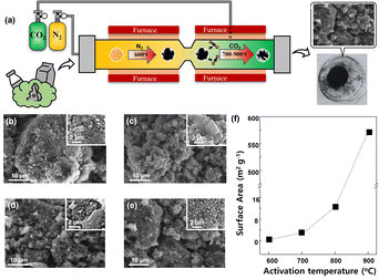
The BAC powder was synthesized by pyrosis and CO2 physical activation in a one-step process without any additional process such as the elimination of chemicals. Fig. 1(a) demonstrates the schematics illustration of the one-pot process of BAC powder. The dried MW powder was carbonized at 600 °C with N2 gas, then the biomass-derived carbon (BC) powder synthesized from MW powder was activated at various temperatures from 700 to 900 °C with CO2 gas. All processes were conducted in the same tube with only gas change. We predicted that during the activation process BC would be damaged by CO2 gas resulting in the destruction of the outer shell of carbon (Fig. S1†), because of which it would be possible to obtain activated carbon with high surface area. To verify this, surface morphologies and surface area of BC and BAC synthesized at 700, 800, and 900 °C were compared (Fig. 1(b)–(f)). Fig. 1(b) shows the smooth surface morphologies of BC. BAC activated at 700 °C had a similar surface morphology (Fig. 1(c)), indicating that pyrosis and activation process at this temperature could not affect the surface area of carbon. However, the BAC samples activated at 800 and 900 °C showed a rougher surface morphology. We further assumed that physical CO2 activation occurs through partial destruction of the outer surface of BAC, resulting in a rough surface and possibly enlarged surface area. To confirm this, the surface area of all samples were examined and compared by BET analysis (Fig. 1(f), S2 and Table S1†). The surface area of BC is 0.673 m2 g−1 and BAC samples activated at 700, 800, and 900 °C were 2.597, 12.324, and 571.611 m2 g−1, respectively. We confirmed that the BAC sample activated at 900 °C has mesoporosity (>20 nm). From this we confirmed that the activation level of BAC has a proportional relationship with increasing temperature. In general, activation process is conducted with temperature range from 700 to 1000 °C to create the high porosity.61 In this study, we restricted the CO2 physical activation to 900 °C because activation temperatures of 700 and 800 °C showed favorable yields (91.07 and 82.37%, respectively), but the yield decreased rapidly (48.18%) at 900 °C (Fig. S3†). Through these results, we determined that 900 °C is an appropriate temperature for physical CO2 activation.Morphologies of BAC and Al2O3 layers
Fig. 2(a) and (d) demonstrate the morphologies of BAC layer and Al2O3 layer from the BAC/PE/Al2O3 separator with their element mappings. The BAC layer is coated on the one side of the PE separator, and it had a rough surface (Fig. 2(a)) similar to the BAC powder activated at 900 °C (Fig. 1(e)) indicating that the BAC layer on the PE separator had a higher surface area derived from BAC. The results further confirmed that the BAC layer of the PE separator was composed of different particle sizes (2–30 μm). EDS mapping of the BAC layer coated on PE separator showed that carbon and fluorine derived from PVDF were uniformly dispersed (Fig. 2(b) and (c)) confirming that the BAC layer was well coated on the only one side of PE separator. The Al2O3 layer was also well coated by nano Al2O3 particles (size ∼ 300 nm) on the PE separator (Fig. 2(d)). Oxygen and aluminum derived from Al2O3 were also well distributed (Fig. 2(e) and (f)). The thickness of BAC and Al2O3 layers was 58.5 and 14.4 μm, respectively (Fig. S4†). Also, it confirms that both sides of PE separator were covered by BAC and Al2O3, respectively. It could be expected that the BAC layer can play a role as not only suppressing effect of LiPS dissolution but also reducing the internal resistance by good electric conductivity. Furthermore, Al2O3 layer could prevent Li dendrite growth and physical contact between cathode and anode as an insulating layer.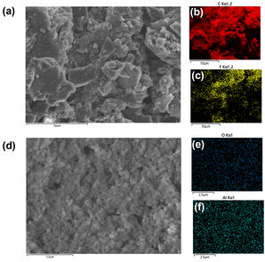 | ||
| Fig. 2 SEM images of BAC (a) coated on the PE separator with elemental mappings of C (b) and F (c). Al2O3 layer coated on the PE separator (d) with elemental mappings of O (e) and Al (f). | ||
Contact angle measurements for separators
Material properties of separators such as wettability with liquid electrolyte and thermal stability are important factors for cell testing. Fig. 3 demonstrates the wettability of the bare PE separator, Al2O3 coated PE separator, and BAC coated PE separator using 1 M LiTFSI in DOL/DME electrolyte. Contact angle values of PE, BAC/PE, and Al2O3/PE separators were 32.2°, 19.4°, and 5.8°, respectively. The dropped liquid electrolyte amount was around 5 μl. As shown in Fig. 3, the BAC and Al2O3 layers had better hydrophilic behavior than the bare PE separator. These results confirmed that the wettability of the separator was significantly enhanced by the BAC and Al2O3 dual coating on the PE separator.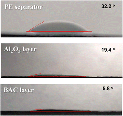 | ||
| Fig. 3 Contact angle measurement of the bare PE separator (a), PE separator coated with Al2O3 layer (b), and PE separator coated with BAC layer using 1 M LiTFSI in DOL/DME. | ||
Thermal shrinkage of separators
Thermal stability of separators is one of the critical parameters in the failure of LIB and LSB.62 To further investigate the thermal stability of PE, Al2O3/PE, and BAC/PE/Al2O3 separators, all samples were placed in a circulating oven with a temperature of 140 °C for 10 min. As shown in Fig. 4, the bare PE separator shrank by 63% after heating and its melting point was approximately 135 °C.63,64 Studies report that adding a ceramic coating can enhance the thermal stability of separators thereby improving their heating resistance.65,66 As expected, the Al2O3/PE separator had favorable thermal stability and lower shrinkage (25%) compared to the PE separator. The BAC layer contributed even more substantially to the heating resistance of the separator (4% shrinkage). These results indicate that the BAC/PE/Al2O3 separator could improve the thermal safety of batteries and prevent issues such as internal short circuits that arise due to a shrinking PE separator.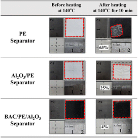 | ||
| Fig. 4 Thermal shrinkage of bare PE separator, single-side coated Al2O3/PE separator, and dual-side coated BAC/PE/Al2O3 separator at 140 °C for 10 min. | ||
Electrochemical behaviors of coin cells with PE and BAC/PE/Al2O3 separators
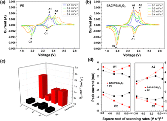
Although the multi-coated separator shows good thermal stability and wettability, there was a possibility that the BAC and Al2O3 layers might influence the internal resistance or Li-ion mobility during the charge and discharge process. To investigate the electrochemical behaviors of coin cells assembled with PE or BAC/PE/Al2O3 separators were examined by CV at different scan rates (0.1–0.4 mV s−1). Coin cells with PE separators showed a typical CV curve of LSB from 0.1 to 0.3 mV s−1. However, the anodic and cathode peaks of the CV curve tested at 0.4 mV s−1 shifted due to the LiPS dissolution during redox reactions. On the other hand, coin cells with BAC/PE/Al2O3 separators had a stable CV curve at all scan rate conditions as shown in Fig. 5(b). In Fig. 5(a), there are two anodic peaks at 2.33 V (peak A1) and 2.39 V (peak A2) and two cathodic peaks at 2.31 V (peak C1) and 2.03 V (peak C2) of coin-cell assembled using PE separator. We previously found that elemental sulfur (octasulfur, S8) reduces to soluble high-order LiPS (Li2S4–Li2S8) at approximately 2.0–2.3 V. Furthermore, the soluble LiPS (Li2S4) reduces at approximately 2.10 V. In the anodic peaks, peaks located at 2.33 and 2.39 V correspond to the two-step transformation from Li2Sx (1 ≤ x ≤ 2) to LiPS and octasulfur (S8). The redox behaviors of coin-cells assembled using BAC/PE/Al2O3 separators had similar CV curves to those assembled using PE separators including two anodic (A1: 2.31 V, A2: 2.40 V) and two cathodic peaks (C1: 2.32 V, C2: 2.02 V), indicating that the electrochemical reactions of both samples are not affected by the addition of a dual coating of BAC and Al2O3 layer on the PE separator. Moreover, it shows sharper peaks in CV curves at 0.1 mV s−1 for 5 cycles than the coin-cell prepared using a bare PE separator, meaning that the Li+ diffusion kinetics during redox reactions is improved by a dual coating on PE separator (Fig. S5†).For further examination, Li+ diffusion coefficients (DLiapp) of the two types of coin-cells was calculated and compared using the Randles–Sevcik equation as follows:26
In the LSB system, Ip is the peak current value in ampere (A), n is the number of electrons transferred in the oxidation–reduction reaction (n = 2 in LSB system), and A is the surface area of the working electrode (cm2), DLiapp is the Li+ diffusion coefficient, CLi is the concentration of Li in liquid electrolyte (mol cm−3), and v is the scan rate value from the CV test (V s−1). The Li+ diffusion coefficient values of coin-cell assembled using bare PE separator at the 0.1 mV s−1 are 9.85 × 10⁻¹², 3.46 × 10⁻¹², 6.16 × 10⁻¹³, and 4.52 × 10⁻¹² cm2 S−1, respectively. In contrast, the sample prepared using the BAC/PE/Al2O3 separator shows higher Li+ diffusion coefficient values of 1.74 × 10⁻¹¹, 2.03 × 10⁻¹², 8.78 × 10⁻¹³, and 7.66 × 10⁻¹² cm2 S−1 (Fig. 5(c)). All Li+ diffusion coefficient values at scan rates of 0.1, 0.2, 0.3, and 0.4 mV s−1 of all samples are shown in Table 1. Fig. 5(d), confirms that the anodic and cathodic peak currents of coin cells assembled using BAC/PE/Al2O3 separators are linear with a square root of all scan rates condition, indicating a diffusion-controlled process.67 However, the anodic and cathodic peak currents of PE separator coin cells showed a non-linear relationship with the square root of scanning rates. We assumed that the LiPS dissolution might affect the electrochemical behaviors during CV testing. Our results indicate that the addition of BAC and Al2O3 layer on the PE separator enhances the Li+ diffusion kinetics during the charge and discharge process.
Charge and discharge performances of coin cells
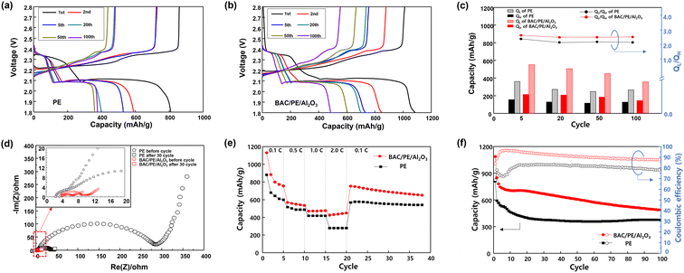
The charge and discharge performances of coin cells assembled using PE and BAC/PE/Al2O3 separators were investigated at 0.1 C-rate for 100 cycles. Fig. 6(a) and (b) reveal the typical charge and discharge profiles of LSB including two representative discharge plateaus at 2.2–2.3 V and 2.1 V. These two discharge plateaus are related to the reduction of octasulfur to high-order LiPS (Li2S4–Li2S8) and Li2Sx (1 ≤ x ≤ 2), corresponding to the CV results of both types of coin cells (Fig. 5(a) and (b)). The discharge capacities of the coin cells with PE separators are 811.8, 590.0, 513.4, 401.1, 359.6, and 386.2 mA h g−1 at 1st, 2nd, 5th, 20th, 50th, and 100th cycle, respectively. In contrast, the coin-cells assembled using BAC/PE/Al2O3 separators delivered higher discharge capacities than that of PE samples (1092.5, 853.3, 761.1, 709.8, 630.8, and 495.2 mA h g−1 at the 1st, 2nd, 5th, 20th, 50th, and 100th cycle, respectively). Thus, a dual-coated PE separator is particularly effective in enhancing the electrochemical performance of LSB. As previously mentioned, the charge and discharge profiles of LSB are composed of a higher plateau (QH) and lower plateau (QL) (Fig. S6†). The values of QH and QL reflect the transformation of solid-state octasulfur to soluble high-order LiPS (Li2S4–Li2S8) and continuing reduction of Li2S4–Li2S8 to insoluble sulfides (Li2Sx, 1 ≤ x ≤ 2), respectively. Thus, QL/QH ratio provides important information on electrochemical stability and reversibility in LSB systems. Fig. 6(c) and Table S2† demonstrate the QH, QL, and QL/QH ratio values of all samples at each cycle. Theoretically, QL/QH ratio of 3 indicates a complete transformation to Li2S and a QL/QH ratio of 2 to Li2S2.68 All samples revealed a lower QL/QH ratio (approximately 2.11–2.61) than the theoretical values, which means that the transformation of soluble LiPS to insoluble Li2Sx (1 ≤ x ≤ 2) was not completed. However, QL/QH ratio of coin-cells assembled using BAC/PE/Al2O3 separators show higher QL/QH ratios (2.61, 2.46, 2.46, and 2.49 at 5th, 20th, 50th, 100th cycle respectively) compared to coin cells using PE separators (2.35, 2.11, 2.15, and 2.11 at the 5th, 20th, 50th, 100th cycle respectively). This result suggests that the dual coating of BAC and Al2O3 layer on the PE separator can enhance the transformation of soluble LiPS to insoluble Li2Sx (1 ≤ x ≤ 2). In addition, from these results, we inferred that the BAC layer which has higher surface area can suppress the LiPS dissolution during the charge and discharge process. Fig. 6(d) shows the Nyquist plot of coin-cell assembled using the PE separator or BAC/PE/Al2O3 separator before and after charge and discharge cycling for 30 cycles. The coin cells with PE separators had a higher charge transfer resistance (38.9 Ω after 30 cycles) compared to coin-cells with BAC/PE/Al2O3 separators (9.0 Ω).EIS measurements revealed that the redox kinetics of coin-cells were improved by a dual coating of BAC and Al2O3 layer on the PE separator. It can be attributed to the good electrical conductivity of BAC (around 0.4–0.5 S cm−1). This value is similar to the commercial activation carbon. We confirmed that the good electrical conductivity by adding BAC layer could decrease the internal resistance, resulting in good electrochemical performances.69–71 The rate performance of both types of coin cells was tested at various C-rate values from 0.1 to 2.0C and 0.1C again (Fig. 6(e)). Coin cells with BAC/PE/Al2O3 separators delivered a higher discharge capacity (757 and 452 mA h g−1) compared to those with PE separators (598, 271 mA h g−1) at the 5th and 20th cycle with the C-rate values of 0.1 and 2.0. When the C-rate values returned to 0.1, coin cells with BAC/PE/Al2O3 separators showed good capacity retention (99.5%). By contrast, coin cells with PE separators had lower capacity retention (94.3%), indicating that the BAC/PE/Al2O3 separator enhances the reversibility of battery cell. To explore the reversible charge and discharge process of LSB samples depending on the separators, the cyclability of both samples was tested at 0.1 C-rate for 100 cycles. As shown in Fig. 6(f), coin-cells with PE separators deliver a discharge capacity of 810 and 377 mA h g−1 at 1st and 100th cycle. The CE of this sample is 68.6 and 78.2%. In the LSB system, LiPS dissolution from the cathode to liquid electrolyte is a major reason for low CE (<80%). These results indicate that coin cells with bare PE separators cannot suppress the LiPS dissolution from cathode to anode, also known as the shuttle effect. On the other hand, the coin cells using BAC/PE/Al2O3 separators show an improved discharge capacity of 1087 and 487 mA h g−1 with high CE (83.9 and 87.5% at 1st and 100th cycle). These results indicate that the large surface area derived from the BAC effectively suppressed the LiPS dissolution during cycling leading to a stable electrochemical performance for LSB.
Suppressive ability of separators
To investigate the suppressive ability of BAC and Al2O3 layer on PE separators, a penetration test was conducted. H-type cells with the two types of separators were prepared with 0.1 M Li2S6 in DME solution (left side), and pure DME solution (right side). In the H-type cell with the bare PE separator, the color of the pure DME solution stored on right side gradually changed to light-yellow color after 20 min because of the diffusion of Li2S6, indicating the shuttle effect starts at the initial state of cycling (Fig. 7). After 4 h, the color of the pure DME solution (right side) changed to reddish-brown color indicating the bare PE separator had no suppressive ability, resulting in irreversible electrochemical reactions during cycling. By contrast, the DME solution in the H-type cell prepared using the BAC/PE/Al2O3 separator showed no noticeable color change for 2 h and turned a light-yellow color after 4 h. These results confirm the blocking effect of BAC/PE/Al2O3 separator. We further hypothesized that the BAC layer was able to absorb LiPS because of their high surface area and large porosity.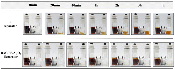 | ||
| Fig. 7 Digital images of LiPS dissolution test in H-type cells with the PE and BAC/PE/Al2O3 separator for 4 hours. | ||
LiPS absorption ability of BAC
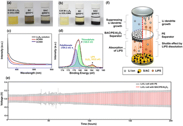
To confirm the absorbing ability of BAC, were soaked in 0.05 M Li2S6 in DOL/DME with 0.1 g of BC and BAC powder and without (i.e., control) were compared (Fig. 8). All samples were maintained for 24 hours to check for color change the samples stored with BAC powder were transparent, whereas the samples with BC powder were a deep-yellow color (Fig. 8(b)). This result demonstrates BAC's outstanding ability to absorb Li2S6. To further test the Li2S6 absorbing ability of BAC, we conducted UV-vis measurements of the Li2S6 in DOL/DME solutions separated from the BC and BAC powder. The absorbance intensity of the solution from BAC sample was weakest compared to the pure Li2S6 in DOL/DME solution and the BC sample, demonstrating that BAC has a strong absorbing ability due to its higher surface area than BC (Fig. 8(c)). After the absorption test, we also conducted an XPS test wherein BAC powder was filtered and dried. Fig. 8(d) shows the S2p spectra of BAC powder. The binding energies at 163.6, 168.0 and 169.2 eV correspond to the LiPS (Li2Sx, 4 < x ≤ 8), thiosulfate, and polythionate, respectively.72 This result suggests that the high surface area of BAC caused not only a physical trapping but also a chemical binding of LiPS resulting in suppressing LiPS dissolution during the charge and discharge process.There are many reports of a possibility of a dual-coated separator for not only LSB but also LMB. It is known that a multi-functional separator which has AC or inorganic layers on its surface can suppress the Li dendrite growth during cycling. Fig. 8(e) shows the voltage–time profiles of Li//Li symmetric cells assembled using bare PE and BAC/PE/Al2O3 separators at current density of 2.0 mA cm−2 for 200 hours. The coin cell assembled using BAC/PE/Al2O3 separators has stable voltage curves with a low over-potential, while the sample with bare PE separator shows a higher over-potential for 200 hours. In the following cycles, voltage profiles of BAC/PE/Al2O3 separators are gradually increased but it is still stable and lower than that of the bare PE separator. This demonstrates that the BAC/PE/Al2O3 separator has the suppressing ability of the Li dendrite growth during the charge and discharge process with good structural stability as shown in Fig. S7 and S8.† Fig. 8(f) depicts the multi-functionality of the dual coating of BAC and Al2O3 layer on the PE separator in the improved electrochemical performance of LSB. This study demonstrates a new opportunity for mass production of activated carbon derived from biomass and its application for Li–S batteries.
Conclusions
LSB could prove to be an excellent solution for the growing needs of large-scale battery industries. LSBs could theoretically be better alternatives to the traditional lithium-ion batteries because of their higher theoretical capacity and energy density but the devices had certain critical issues. Our study demonstrates an effective PE separator with a dual-side coating of Biomass-derived activated carbon (BAC) and Al2O3 (BAC/PE/Al2O3 separator) that could solve for most issues with LSBs. The BAC powder was successfully synthesized via a one-pot process using a specially designed tube furnace, which was used as a coating layer for modification of the commercial PE separator. The BAC/PE/Al2O3 separator shows enhanced material properties such as wettability and thermal stability compared to the bare PE separator. It also effectively suppresses the dissolution of LiPS and improves the Li+ diffusion kinetics. Thus, the LSB coin-cell assembled using BAC/PE/Al2O3 separators exhibited improved discharge capacities compared to the coin cells with bare PE separators. Moreover, BAC/PE/Al2O3 separators were able to successfully suppress Li dendrite growth. This facile method of synthesizing BAC and its application to multifunctional separators will provide a new way to increase the electrochemical performance of LSB.Author contributions
S. Jo, J.-W. Hong, and J. Heo performed the experiments, analysis of the data, and wrote the manuscript. T. Momma, Y. Park, and J.-W. Park reviewed this paper and provided valuable comments. S. Ahn wrote and reviewed the manuscript. This manuscript has been reviewed and edited by all contributing authors.Conflicts of interest
There are no conflicts to declare.Acknowledgements
This work was partly supported by Sangji University Graduate School, by National Research Foundation of Korea (NRF) grant funded by the Korea government (MSIT, Korea) (No. NRF-2021R1G1A1094175), by Korea Electrotechnology Research Institute (KERI) (No. 23A01030), and by the Ministry of Trade, Industry & Energy (MOTIE, Korea) (No. 20014581), by the Korea Institute of Energy Technology Evaluation and Planning (KETEP) grant funded by the Korea government (MOTIE) (20215410100030).References
- M. Chen, Y. Zhang, G. Xing, S.-L. Chou and Y. Tang, Energy Environ. Sci., 2021, 14, 3323–3351 RSC
.
- Q. Zhang, Q.-F. Dong, M.-S. Zheng and Z.-W. Tian, J. Electrochem. Soc., 2011, 158, A443 CrossRef CAS
.
- A. A. Habib, S. Motakabber and M. I. Ibrahimy, 2019 IEEE International, 2019, 43–47 Search PubMed
.
- X.-Y. Shan, F. Li, D.-W. Wang and H.-M. Cheng, Energy Storage Mater., 2016, 3, 66–68 CrossRef
.
- H. D. Yoo, E. Markevich, G. Salitra, D. Sharon and D. Aurbach, Mater. Today, 2014, 17, 110–121 CrossRef CAS
.
- A. Masias, J. Marcicki and W. A. Paxton, ACS Energy Lett., 2021, 6, 621–630 CrossRef CAS
.
- F. Schipper, E. M. Erickson, C. Erk, J.-Y. Shin, F. F. Chesneau and D. Aurbach, J. Electrochem. Soc., 2016, 164, A6220 CrossRef
.
- D. Di Lecce, V. Marangon, H.-G. Jung, Y. Tominaga, S. Greenbaum and J. Hassoun, Green Chem., 2022, 24, 1021–1048 RSC
.
- D. Di Lecce, R. Verrelli and J. Hassoun, Green Chem., 2017, 19, 3442–3467 RSC
.
- J. E. Knoop and S. Ahn, J. Energy Chem., 2020, 47, 86–106 CrossRef
.
- M. Rana, S. A. Ahad, M. Li, B. Luo, L. Wang, I. Gentle and R. Knibbe, Energy Storage Mater., 2019, 18, 289–310 CrossRef
.
- M. Zhao, B.-Q. Li, X.-Q. Zhang, J.-Q. Huang and Q. Zhang, ACS Cent. Sci., 2020, 6, 1095–1104 CrossRef CAS PubMed
.
- A. Liu, X. Liang, X. Ren, W. Guan and T. Ma, Electrochem. Energy Rev., 2022, 5, 112–144 CrossRef CAS
.
- H. Qian, H. Ren, Y. Zhang, X. He, W. Li, J. Wang, J. Hu, H. Yang, H. M. K. Sari, Y. Chen and X. Li, Electrochem. Energy Rev., 2022, 5, 2 CrossRef CAS
.
- G. Cao, R. Duan and X. Li, EnergyChem, 2023, 5, 100096 CrossRef CAS
.
- L. Chen, Y. Xu, G. Cao, H. M. K. Sari, R. Duan, J. Wang, C. Xie, W. Li and X. Li, Adv. Funct. Mater., 2022, 32, 2270052 CrossRef
.
- M. Rahman, X. Wang and C. Wen, J. Appl. Electrochem., 2014, 44, 5–22 CrossRef CAS
.
- M. Park, H. Sun, H. Lee, J. Lee and J. Cho, Adv. Energy Mater., 2012, 2, 780–800 CrossRef CAS
.
- M.-K. Song, S. Park, F. M. Alamgir, J. Cho and M. Liu, Mater. Sci. Eng., R, 2011, 72, 203–252 CrossRef
.
- P. Shi, X. Q. Zhang, X. Shen, R. Zhang, H. Liu and Q. Zhang, Adv. Mater. Technol., 2020, 5, 1900806 CrossRef CAS
.
- Z. A. Ghazi, Z. Sun, C. Sun, F. Qi, B. An, F. Li and H. M. Cheng, Small, 2019, 15, 1900687 CrossRef PubMed
.
- A. Varzi, K. Thanner, R. Scipioni, D. Di Lecce, J. Hassoun, S. Dörfler, H. Altheus, S. Kaskel, C. Prehal and S. A. Freunberger, J. Power Sources, 2020, 480, 228803 CrossRef CAS
.
- G. Li, Z. Chen and J. Lu, Chem, 2018, 4, 3–7 CAS
.
- C. Yang, P. Li, J. Yu, L.-D. Zhao and L. Kong, Energy, 2020, 201, 117718 CrossRef CAS
.
- Y. X. Yin, S. Xin, Y. G. Guo and L. J. Wan, Angew. Chem., Int. Ed. Engl., 2013, 52, 13186–13200 CrossRef CAS PubMed
.
- S. Ahn, T. Noguchi, T. Momma, H. Nara, T. Yokoshima, N. Togasaki and T. Osaka, Chem. Phys. Lett., 2020, 749, 137426 CrossRef CAS
.
- S. Ahn, H. Mikuriya, E. Kojima and T. Osaka, J. Electrochem. Soc., 2022, 169, 030546 CrossRef CAS
.
- X. Ji and L. F. Nazar, J. Mater. Chem., 2010, 20, 9821–9826 RSC
.
- M. Wang, X. Xia, Y. Zhong, J. Wu, R. Xu, Z. Yao, D. Wang, W. Tang, X. Wang and J. Tu, Chem.–Eur. J., 2019, 25, 3710–3725 CrossRef CAS PubMed
.
- A. Fu, C. Wang, F. Pei, J. Cui, X. Fang and N. Zheng, Small, 2019, 15, 1804786 CrossRef PubMed
.
- Q. Xiao, G. Li, M. Li, R. Liu, H. Li, P. Ren, Y. Dong, M. Feng and Z. Chen, J. Energy Chem., 2020, 44, 61–67 CrossRef
.
- N. Nakamura, H. Mikuriya, E. Kojima, S. Ahn, K. Yamabuki, T. Momma and T. Osaka, J. Electrochem. Soc., 2021, 168, 110552 CrossRef CAS
.
- N. Nakamura, T. Yokoshima, H. Nara, H. Mikuriya, A. Shiosaki, S. Ahn, T. Momma and T. Osaka, J. Electrochem. Soc., 2021, 168, 040517 CrossRef CAS
.
- Y. Yang, G. Yu, J. J. Cha, H. Wu, M. Vosgueritchian, Y. Yao, Z. Bao and Y. Cui, ACS Nano, 2011, 5, 9187–9193 CrossRef CAS PubMed
.
- Z. A. Ghazi, X. He, A. M. Khattak, N. A. Khan, B. Liang, A. Iqbal, J. Wang, H. Sin, L. Li and Z. Tang, Adv. Mater., 2017, 29, 1606817 CrossRef PubMed
.
- T. Lei, W. Chen, W. Lv, J. Huang, J. Zhu, J. Chu, C. Yan, C. Wu, Y. Yan and W. He, Joule, 2018, 2, 2091–2104 CrossRef CAS
.
- S. Bai, X. Liu, K. Zhu, S. Wu and H. Zhou, Nat. Energy, 2016, 1, 1–6 Search PubMed
.
- F. Wu, J. T. Lee, N. Nitta, H. Kim, O. Borodin and G. Yushin, Adv. Mater., 2015, 27, 101–108 CrossRef CAS PubMed
.
- H.-L. Wu, M. Shin, Y.-M. Liu, K. A. See and A. A. Gewirth, Nano Energy, 2017, 32, 50–58 CrossRef CAS
.
- H. Ye, J. Sun, S. Zhang, T. Zhang, Y. Zhao, C. Song, Q. Yao and J. Y. Lee, Chem. Eng. J., 2021, 410, 128284 CrossRef CAS
.
- B. D. McCloskey, J. Phys. Chem. Lett., 2015, 6, 4581–4588 CrossRef CAS PubMed
.
- J.-H. Kim, Y.-H. Lee, S.-J. Cho, J.-G. Gwon, H.-J. Cho, M. Jang, S.-Y. Lee and S.-Y. Lee, Energy Environ. Sci., 2019, 12, 177–186 RSC
.
- Z. Wang, W. Huang, J. Hua, Y. Wang, H. Yi, W. Zhao, Q. Zhao, H. Jia, B. Fei and F. Pan, Small Methods, 2020, 4, 2000082 CrossRef CAS
.
- J. Balach, T. Jaumann, M. Klose, S. Oswald, J. Eckert and L. Giebeler, Adv. Funct. Mater., 2015, 25, 5285–5291 CrossRef CAS
.
- P. Han and A. Manthiram, J. Power Sources, 2017, 369, 87–94 CrossRef CAS
.
- S. H. Chung and A. Manthiram, Adv. Funct. Mater., 2014, 24, 5299–5306 CrossRef CAS
.
- M. K. Rybarczyk, H.-J. Peng, C. Tang, M. Lieder, Q. Zhang and M.-M. Titirici, Green Chem., 2016, 18, 5169–5179 RSC
.
- D. B. Babu, K. Giribabu and K. Ramesha, ACS Appl. Mater. Interfaces, 2018, 10, 19721–19729 CrossRef CAS PubMed
.
- C.-H. Chang, S.-H. Chung and A. Manthiram, J. Mater. Chem. A, 2015, 3, 18829–18834 RSC
.
- W.-G. Lim, S. Oh, J. Jeong, W. Jang, K. I. Shim, S. Kim, J. W. Han, S. G. Im and J. Lee, ACS Appl. Energy Mater., 2021, 4, 611–622 CrossRef CAS
.
- D. Muthuraj, R. Murugan, P. R. Rayappan, G. R. Kandregula and K. Ramanujam, New J. Chem., 2022, 46, 3185–3198 RSC
.
- Z. Zhang, Y. Lai, Z. Zhang, K. Zhang and J. Li, Electrochim. Acta, 2014, 129, 55–61 CrossRef CAS
.
- T. Yim, S. H. Han, N. H. Park, M. S. Park, J. H. Lee, J. Shin, J. W. Choi, Y. Jung, Y. N. Jo and J. S. Yu, Adv. Funct. Mater., 2016, 26, 7817–7823 CrossRef CAS
.
- S. H. Kim, J. S. Yeon, R. Kim, K. M. Choi and H. S. Park, J. Mater. Chem. A, 2018, 6, 24971–24978 RSC
.
- M. Li, Y. Wan, J.-K. Huang, A. H. Assen, C.-E. Hsiung, H. Jiang, Y. Han, M. Eddaoudi, Z. Lai and J. Ming, ACS Energy Lett., 2017, 2, 2362–2367 CrossRef CAS
.
- X.-J. Hong, C.-L. Song, Y. Yang, H.-C. Tan, G.-H. Li, Y.-P. Cai and H. Wang, ACS Nano, 2019, 13, 1923–1931 CAS
.
- H. Lu and X. J. S. E. Zhao, Sustainable Energy Fuels, 2017, 1, 1265–1281 RSC
.
- J. Wang, P. Nie, B. Ding, S. Dong, X. Hao, H. Dou and X. Zhang, J. Mater. Chem. A, 2017, 5, 2411–2428 RSC
.
- J. Deng, M. Li and Y. Wang, Green Chem., 2016, 18, 4824–4854 RSC
.
- S. C. Jo, J. W. Hong, I. H. Choi, M. J. Kim, B. G. Kim, Y. J. Lee, H. Y. Choi, D. Kim, T. Kim and K. J. Baeg, Small, 2022, 18(21), 2200326 CrossRef CAS PubMed
.
- F. Ahmad, W. M. A. W. Daud, M. A. Ahmad, R. Radzi and A. A. Azmi, J. Environ. Chem. Eng., 2013, 1, 378–388 CrossRef CAS
.
- X. Jiang, X. Zhu, X. Ai, H. Yang and Y. Cao, ACS Appl. Mater. Interfaces, 2017, 9, 25970–25975 CrossRef CAS PubMed
.
- S. S. Zhang, J. Power Sources, 2007, 164, 351–364 CrossRef CAS
.
- C. Shi, P. Zhang, L. Chen, P. Yang and J. Zhao, J. Power Sources, 2014, 270, 547–553 CrossRef CAS
.
- X. Chen, S. Chen, Y. Lin, K. Wu and S. Lu, Ceram. Int., 2020, 46, 24689–24697 CrossRef CAS
.
- H. Cheng, J. Hou, Y. Wang, Z. Zhu, Y. Zhang, X. Li and Y. Zhang, Ceram. Int., 2022, 48(17), 24811–24821 CrossRef CAS
.
- X. Gao, D. Zhou, Y. Chen, W. Wu, D. Su, B. Li and G. Wang, Commun. Chem., 2019, 2, 1–10 CrossRef CAS
.
- H. Zhou, Q. Tang, Q. Xu, Y. Zhang, C. Huang, Y. Xu, A. Hu and X. Chen, RSC Adv., 2020, 10, 18115–18123 RSC
.
- Z. Wu, X. He, J. Zhou, X. Yang, L. Sun, H. Li, Y. Pan and L. Yu, J. Alloys Compd., 2023, 935, 168136 CrossRef CAS
.
- Z. Zhang, Y. Lai, Z. Zhang and J. Li, Solid State Ionics, 2015, 278, 166–171 CrossRef CAS
.
- S. Xia, J. Song, Q. Zhou, L. Liu, J. Ye, T. Wang, Y. Chen, Y. Liu, Y. Wu and T. van Ree, Advanced Science, 2023, 2301386 CrossRef CAS PubMed
.
- S.-H. Moon, J.-H. Kim, J.-H. Shin, J.-S. Jang, S.-B. Kim, S.-N. Lee, S.-H. Kwon and K.-W. J. J. o. A. Park, J. Alloys Compd., 2022, 904, 164120 CrossRef CAS
.
Footnotes |
| † Electronic supplementary information (ESI) available. See DOI: https://doi.org/10.1039/d3ra05891c |
| ‡ These authors contributed equally to this work. |
| This journal is © The Royal Society of Chemistry 2023 |

