DOI:
10.1039/D3TB00852E
(Paper)
J. Mater. Chem. B, 2023,
11, 6095-6105
Magnetically actuated hydrogel-based capsule microrobots for intravascular targeted drug delivery†
Received
17th April 2023
, Accepted 30th May 2023
First published on 31st May 2023
Abstract
Microrobots for targeted drug delivery in blood vessels have attracted increasing interest from researchers. In this work, hydrogel-based capsule microrobots are used to wrap drugs and deliver drugs in blood vessels. In order to prepare capsule microrobots of different sizes, a triaxial microfluidic chip is designed and built, and the formation mechanism of three flow phases including the plug flow phase, bullet flow phase and droplet phase during the preparation of capsule microrobots is studied. The analysis and simulation results show that the size of the capsule microrobots can be controlled by the flow rate ratio of two phases in the microfluidic chip, and when the flow rate of the outer phase is 20 times that of the inner phase in the microfluidic chip, irregular multicore capsule microrobots can be prepared. On this basis, a three degree of freedom magnetic drive system is developed to drive the capsule microrobots to reach the destination along the predetermined trajectory in the low Reynolds number environment, and the magnetic field performance of the magnetic drive system is simulated and analyzed. Finally, in order to verify the feasibility of targeted drug delivery of the capsule microrobots in the blood vessel, the motion process of the capsule microrobots in the vascular microchannel is simulated, and the relationship between the motion performance of the capsule microrobots and the magnetic field is studied. The experimental results show that the capsule microrobots can reach a speed of 800 μm s−1 at a low frequency of 0.4 Hz. At the same time, the capsule microrobots can reach a peak speed of 3077 μm s−1 and can continuously climb over a 1000 μm high obstacle under a rotating magnetic field of 2.4 Hz and 14.4 mT. Experiments show that the capsule microrobots have excellent drug delivery potential in similar vascular curved channels driven by this system.
1 Introduction
Cardiovascular diseases such as myocardial infarction, stroke, blood clots, and peripheral artery disease are potentially life-threatening diseases, and it is estimated that more than one-third of people in the world die from cardiovascular disease.1,2 In the early stages, the typical treatment for cardiovascular disease is intravenous. However, this approach is poorly targeted, and the high dose injection and rapid spread of drugs can have toxic side effects on other healthy cells and tissues, so newer and better treatments are needed. Targeted delivery of drugs can improve deficiencies in traditional therapies by delivering drugs to specific sites, improving the therapeutic efficacy.3,4
Hydrogels are considered to be ideal carriers for targeted drug delivery due to their good biocompatibility and gradual degradation in vivo.5–7 A large number of studies have shown that the use of magnetic hydrogels can induce the on-demand release of drugs at the right place and time with the best concentration by precisely adjusting external stimuli, which can not only reduce the enzymolysis of drugs and toxicity to other tissues, but also extend the administration time. In addition, the remote application of the external magnetic field has no limit on the depth of tissue penetration, and there is almost no harm to the human body. Therefore, magnetic response targeting and controlled release of drugs in hydrogels have attracted much attention as novel and effective drug delivery methods.8–10 At present, magnetic hydrogels with multiple response characteristics such as pH response,11 thermal response12,13 and magnetic response14 have been developed, as well as magnetic hydrogels with various shapes, such as spiral,15 spherical16 and bionic.17 With the wide application of microrobots, microrobots based on magnetic hydrogels have been developed effectively. However, for practical applications of microrobots in biomedicine, there are still many research studies to be performed in terms of biocompatibility,18 cytotoxicity,19 drug loading modes of microrobots20 and control of microrobots.21 Magnetic field driving modes of microrobots can be divided into three types: rotating magnetic field,22 gradient magnetic field23 and oscillating magnetic field.24 These magnetic actuation methods have been proven to be safe and efficient, and it can drive the magnetic microrobots to accurately reach the target position through controllable actuation.25,26 Based on the aforementioned controllable actuation of the microrobots and various model analyses for the transport of druggable particles in the microvasculature,27,28 it is possible to realize the targeted drug delivery of the capsule microrobot in the blood vessel by magnetic actuation.
Compared with the random diffusion method of traditional drug injection for cardiovascular disease treatment, the manipulation of the capsule microrobots in a liquid environment inside the vessel would be more flexible. However, the current research on capsule microrobots mainly focuses on the drug loading performance, drug release mode, and performance studies on various single magnetic field systems.29–32 The fabrication mechanism, repetitive fabrication, and size controllability of the capsule microrobot with different shapes and sizes still need to be studied in depth. In addition, the complexity, high cost, and difficulty in manipulation of the microrobot actuating device and actuating mode also need to be improved.33,34
Here, we conducted an in-depth study focusing on the above issues. A three coaxial microfluidic chip is designed and constructed for this purpose. In depth, the fabrication mechanism, size controllability, and reproducible fabrication of different shaped and sized capsule microrobots in microfluidic chips are studied, and the plug, bullet, and droplet flows occurring during the formation of the capsule microrobots are simulated and analyzed. To guarantee the operation of the capsule microrobot, a facile, low-cost, and user-friendly three degrees of freedom magnetic driven system is built, and the performance of the magnetic driven system is simulated and analyzed. In order to verify the feasibility of targeted drug delivery of the capsule microrobot in blood vessels, the motion process of the capsule microrobot in the blood vessel microchannel is simulated, the relationship between the motion performance of the capsule microrobot and magnetic field is studied, and the obstacle crossing ability of capsule microrobot under the control of this system is analyzed. Finally, an experiment is conducted to verify the above research. Compared with rigid capsule microrobots reported for drug transport in the gastrointestinal tract,35,36 our capsule microrobots are easier to prepare, cost less and due to the use of biocompatible materials, cause less damage to human tissues due to the use of biocompatible materials. Compared with capsule microrobots that use the same materials for drug delivery,37,38 our capsule microrobots will have lower cost, higher responsive sensitivity, good motion efficiency and maneuverability. Fig. 1 shows the schematic diagram of the capsule microrobot achieving drug targeting in blood vessels. After the capsule microrobot is prepared by a triaxial microfluidic chip, it is injected intravenously with a syringe, and targeted drug delivery is carried out in blood vessels through an external magnetic field.
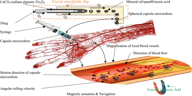 |
| | Fig. 1 Schematic of targeted drug delivery by capsule microrobots in blood vessels. | |
2 Experimental section
2.1 Materials
Deionized water is purified using a purifier. Mineral oil, span 80, glacial acetic acid, and CaCl2 are purchased from Shanghai Sinopharm Group Chemical Reagent Co., Ltd. Fe3O4 nanoparticle is purchased from the Suzhou Beasley New Material Co., Ltd. Sodium alginate is purchased from the Tianjin Fuchen Chemical Factory and CaCO3 is purchased from the Wuxi Yatai United Chemical Co., Ltd. Indomethacin is purchased from Sinopharm Chemical Reagent Co., LTD.
2.2 Preparation of microfluidic chips
The microfluidic chip uses capillary glass tubes as the main material, and the glass tubes are nested within each other to form several microchannels. The core of the device is a three-coaxial structure, which can generate the core–shell droplet in one step. Two glass tubes with an inner diameter of 0.2 mm, an outer diameter of 0.3 mm and an inner diameter of 0.9 mm, an outer diameter of 1.1 mm are pulled off by using a PC-100 multifunctional tensioner, and sharp points are produced. The sharp points are sanded until the aperture remained around 300 μm for the introduction of internal and medium phase solutions of microfluidic chips. Another glass tube with an inner diameter of 1.8 mm and an outer diameter of 2 mm is used for the introduction of the external phase solution of the microfluidic chip without any treatment. In the case of ensuring that the three glass tubes are coaxial, they are fixed on the PMMA plastic sheet using adhesive. The glass tube used for the external phase input needs to extend 10 mm compared to the plastic sheet to facilitate solution collection. Finally, an adhesive is used to bond the pipette head to the three glass tube input ends for easy connection of the flow pump.
2.3 Construction of the magnetic drive system
In order to realize the transportation of the capsule microrobot, a coil system with three degrees of freedom (two X-axis coils, two Y-axis coils, and two Z-axis coils with a diameter of 0.35 mm) is established. The drive hardware of the coil system consists of the system controller motherboard and a coil drive board and a DC power supply (Fig. 2(a)). The main controller uses a STM32F103ZET6 control chip, mainly using PWM, IO, software timer, UART module and other system resources. The bottom layer of the system is designed and communicated by FreeRTOS, an embedded real-time operating system. The output of PWM will be interrupted by the software timer in the main controller to generate a control signal, and then the IR2104 will control the on–off of the MOS tube IRF3205 to drive the electromagnetic coil. The camera on the top of the coil can collect the real-time motion image of the capsule microrobots and send it back to the main controller screen. Artificial control of capsule microrobots speed and direction will be allowed by screen mapping. The current of the three axial coils is provided by an external adjustable power supply, and the current magnitude, direction and frequency can be precisely controlled by controlling the PWM duty cycle. The components of the magnetic field on each axis can be adjusted by an electric current and generate spatially uniform magnetic fields as needed.
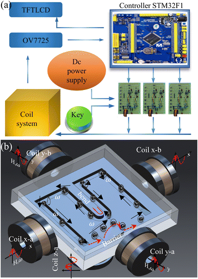 |
| | Fig. 2 (a) Schematic of magnetic drive system connection. (b) Schematic of simulated transport by the capsule microrobots. | |
2.4 Design of propulsion experiment for capsule microrobots
To characterize the movement behavior of the capsule microrobots in the blood vessel, the capsule microrobots are dispersed in a plastic container (30 mm × 30 mm × 20 mm) made of PMMA, which is placed in the center of the platform. The container is carved with simulated vascular microchannels at the bottom and filled with CaCl2 solution (Fig. 2(b)). The main controller and coil are used to apply a suitable rotating magnetic field, and the OV7725 camera continuously records the movement. After extracting the image, the movement speed of the capsule microrobots can be accurately calculated according to the distance it moves in a certain time. In addition, in order to simulate, as much as possible, the obstruction encountered by the movement of the capsule microrobots in the blood vessel, an epoxy adhesive is used to set up a raised barrier at the bottom of the container. And based on the analysis of the advance process of capsule microrobots, the ability to accurately locate and overcome obstacles is tested.
3 Results and discussion
3.1 Preparation process of capsule microrobots
Calcium alginate hydrogel is widely used in the field of drug encapsulation and tissue engineering due to its spherical shape, small size, and low cost. The magnetic hydrogel based on calcium alginate not only has good biocompatibility, but also can respond to the changes in the external magnetic field. From the perspective of application scenarios, it is the most suitable for drug targeting.
Fig. 3 shows the preparation process of capsule microrobots (see Video S1, ESI†). Three syringe pumps and syringes are used in the experiment. Indomethacin drug solution (0.3%(w/v)) is injected into the microchannel of the core layer, mixed solutions containing sodium alginate solution (1%(w/v)), CaCO3 solution (0.5%(w/v)) and magnetic particles (2.5%(w/v)) are injected into the microchannel of the middle layer, and mixed solutions containing Span 80 (5%(v/v)), mineral oil (5%(v/v)) and glacial acetic acid (1%(v/v)) are injected into the gel phase of the shell layer. At the outlet of the microchannels in the inner core layer and the middle layer, the dispersed phase solution will break and form droplets due to the action of surface tension and shear force (relatively, the inner side is the dispersed phase and the outer side is the continuous phase). The surface tension determines the formation of droplets, and the shear force determines the fracture of the dispersed phase solution. The magnitude of the shear force is determined by the ratio Rq of the flow rate of the continuous phase (Qc) and the flow rate of the dispersed phase Qd, and Rq also determines the size and shape of the droplets. In the microfluidic chip, the plug flow phase, bullet flow phase and droplet phase can be formed in the microchannel by adjusting the ratio of two-phase flow velocity. The dynamic simulation of the two-phase flow of fluid in the pipe (only at the junction of the intermediate and outer layers, with the same interface principle) was performed using COMSOL multiphysics software (Fig. 4(a)). The fluid dynamics field in the microchannel is solved by the incompressible N–S equation.
| |  | (1) |
Where
ρ is the density of the fluid,
v is the flow velocity field,
p is the pressure of the fluid,
I is the unit diagonal matrix,
η is the dynamic viscosity, and
Fst is the surface tension. The phase field interface uses the following equation:
| |  | (3) |
| |  | (4) |
where
ϕ is the phase field variable,
λ is the mixed energy density,
γ is the mobility (
γ =
χε2,
χ is the migration adjustment coefficient),
ε is the capillary density,
φ is the phase field cofactor, and
fext is the external free energy. The density and viscosity properties of a fluid are controlled by the following equation:
| |  | (5) |
where
ρc and
ρd,
μc and
μD are the density and viscosity of the continuous and dispersed phase fluids respectively.
 |
| | Fig. 3 Schematic of the preparation process of capsule microrobots. | |
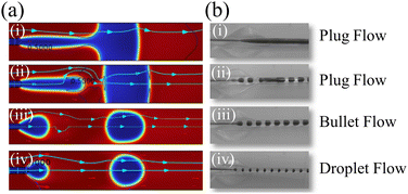 |
| | Fig. 4 (a) Simulated diagrams of three flow phases: plug phase, bullet phase and droplet phase in the microfluidic chip. (b) Experimental diagrams of three flow phases: plug phase, bullet phase and droplet phase in the microfluidic chip. | |
When Rq is large, a droplet is formed, and when Rq is small, a plug flow is formed. Fig. 4a(i) shows when the Qd constant and Qc increase from zero, because the flow rate of the continuous phase at this time is not enough to completely break the binding of the viscous force on the dispersed phase solution, and the rapid gel of sodium alginate solution and Ca2+, the microchannel will be completely blocked. When Qc continues to increase, the inner solution begins to show fracture and the blockage appears broken, but at this point, it is still a plug flow (Fig. 4a(ii)). When Qc increases to a certain value (Qc > Qd), the blockage disappears and forms bullet-shaped droplets (Fig. 4a(iii)). When Qc continues to increase, the fracture situation intensifies, ultimately forming spherical droplets in the periodic competition between the viscous force and surface tension (Fig. 4a(iv)). Fig. 4(b) shows the experimental results. When Qc = 0, the microfluidic chip is blocked (Fig. 4b(i)). When Qc = 0.5Qd, the blockage broke (Fig. 4b(ii)). When Qc = Qd, a bullet-shaped capsule microrobot is generated in the microfluidic chip. When Qc = 1.5Qd, a spherical capsule microrobot is generated within the microfluidic chip. The simulation diagram corresponds to the experimental result diagram one by one, with a high degree of consistency.
The four processes of droplet generation in the microchannel are simulated in Fig. 5a(i–iv) (droplet will generate capsule microrobots after the gel reaction), and at the same time, a series of studies on the influence of the flow rate ratio Rq of the two-phase solution on the shape and size of the droplets are conducted. In the experiment, Qd is maintained at 0.2 mL min−1, when 0 mL min−1 ≤ Qc ≤ 0.15 mL min−1 (0 ≤ Rq ≤0.75), due to the rapid gel reaction of the outermost layer, a stable plug flow will be formed, and this process will cause blockage in the device. When 0.15 mL min−1 ≤ Qc ≤ 0.32 mL min−1 (0.75 ≤ Rq ≤ 1.65), the blockage appears to break, and monodisperse bullet-shaped capsules are formed after the gel. When 0.32 mL min−1 ≤ Qc ≤ 2 mL min−1 (1.65 ≤ Rq ≤ 10), the flow rate increased and the shear force increased, forming spherical capsule microrobots under the action of surface tension. However, it is worth noting that when the flow rate of the external phase increases to a certain value, the droplets are rapidly generated before the gel reaction begins, and it is easy for two capsules to adhere to each other. Fig. 5(b) depicts the relationship between the flow rate ratio and the capsule radius and the fitting curve of the spherical capsule microrobots (Rd = 669.1472 − 92.7771x + 4.8577x2), which shows that the size of the spherical capsule microrobots can be realized by the adjustment of the flow rate as required.Fig. 6 shows the capsule microrobots actually prepared using themicrofluidic chip. Fig. 6(i) and (ii) respectively show the capsule microrobots prepared when Qc is 2 mL min−1 and 4 mL min−1. It can be seen that when the continuous phase flow rate exceeds a certain value, the shape of the capsule microrobots will gradually change from spherical to irregular multi-core shape. Fig. 6(iii) shows the capsule microrobots with a diameter of 460 μm (flow rate of 0.01 mL min−1 for the core layer, 0.1 mL min−1 for the middle layer, and 1 mL min−1 for the shell layer). Fig. 6(iv) is the structure diagram of the capsule microrobots. In addition, comparisons were made with reported microfluidic devices and preparation techniques, which are listed in Table 1. From previous studies in Table tbl:example1, it can be seen that although the T-shaped microfluidic device adopted by W. Chen et al. (2021)20 could be generated at a low cost, the hydrogel microspheres prepared were large in size, low in surface quality, and employed a more complex soft lithography process. K. Enck et al. (2020)39 could prepare hydrogel microspheres of a smaller size and higher surface quality, but they used the laser cutting process, resulting in a higher cost. Z. Chen et al. (2022)40 used a similar method to the one used in this experiment, but it used mechanical processing technology, making the operation more complex. E. Um et al. (2008)41 and M.-H. Wu et al. (2010)42 were able to prepare smaller hydrogel microspheres using a double T-shaped microfluidic device, but the soft lithography process used made the operation more complex and costly. Similarly Y. Morimoto et al. (2009)43 and Q. Zhang et al. (2019)44 and H. Shieh et al. (2021)45 have used different microfluidic devices, but all had high costs and complex manufacturing processes. The results show that the triaxial microfluidic chip designed by us can meet the requirements of high surface quality and low cost, and greatly reduce the complexity of the manufacturing process. The dimensional accuracy can be achieved by adjusting the size of the glass tube in the microfluidic equipment. The chip we designed can prepare drug-loaded capsule microrobots with good surface quality and high internal uniformity. The size and shape of the capsule microrobot can be adjusted by adjusting the ratio of the two-phase flow rates and can be prepared in bulk by this microfluidic chip.
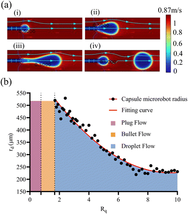 |
| | Fig. 5 (a) Simulation diagram of the formation process of spherical droplets. (b) The relationship curves of three flow phases and the size of capsule microrobot with different Rq. | |
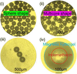 |
| | Fig. 6 (i) Monodisperse spherical capsule microrobots. (ii) Irregular multicore shaped capsule microrobots. (iii) Capsule microrobots with a diameter of 460 μm. (iv) Schematic of the capsule microrobots structure. | |
Table 1 Performance comparison of different microfluidic devices based on the preparation of hydrogel microspheres with different sizes
| Microfluidic devices |
Study |
Dimensional accuracy |
Surface quality |
Manufacturing technology |
Cost |
| T-shape |
W. Chen et al. (2021) |
7.5–20 mm |
Low |
Soft lithography |
Low |
| K. Enck et al. (2020) |
80–100 μm |
High |
Laser cutting |
High |
| Double coaxial |
Z. Chen et al. (2022) |
100–350 μm |
High |
Machining |
Low |
| Double T-shaped |
E. Um et al. (2008) |
40–100 μm |
High |
Soft lithography |
High |
| M.-H. Wu et al.(2010) |
150–370 μm |
Low |
Soft lithography |
High |
| Axial symmetry |
Y. Morimoto et al. (2009) |
59–207 μm |
High |
Stereo lithography |
High |
| Q. Zhang et al. (2019) |
44–93 μm |
High |
Soft lithography |
High |
| Combination shape |
H. Shieh et al.(2021) |
92–195 μm |
High |
Soft lithography |
High |
3.2 Performance of the magnetic actuation system
The developed magnetic drive system outputs the control voltage through the coil drive board (Fig. 7(a). The coil drive circuit consists of MOSFET, IR2104 and other switch components, which greatly reduces the complexity and cost of the drive system. The system uses a charged cylindrical coil to generate a magnetic field, and different magnetic fields can be applied by controlling the voltage. The constructed coil device is shown in Fig. 7(b). The magnetic drive system uses Sine PWM to generate a controllable sinusoidal voltage (Fig. 7(c)), and the amplitude of the sinusoidal voltage can be adjusted by adjusting the duty cycle of the square wave. Fig. 7(d) and (e) show the sinusoidal voltage of 0.4 Hz and 111 Hz output by the magnetic drive system. The frequency of sinusoidal voltage can be continuously adjusted from 0 to 111 Hz with an oscilloscope. At the same time, the peak sinusoidal voltage output by the magnetic drive system can be controlled by an external DC power supply.
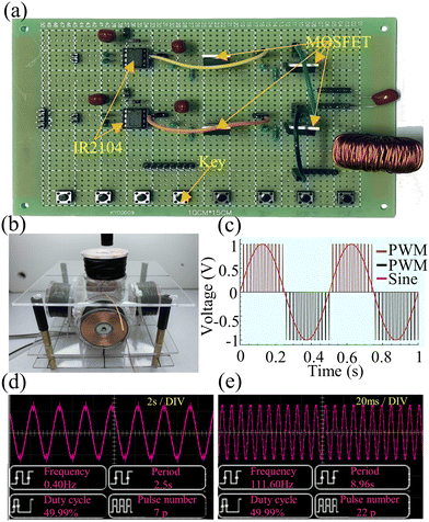 |
| | Fig. 7 (a) Schematic of the coil drive plate. (b) Schematic diagram of the coil device. (c) Schematic of the Sine PWM. (d) A sine wave at 0.4 Hz microcapsules. (e) A sine wave at 111Hz microcapsules. | |
In order to ensure the uniformity of the magnetic field in the device, the magnetic field distribution is simulated using COMSOL MultiPhysics software based on the established magnetic drive system. In Fig. 8(a–d), the magnetic flux density surface maps of three pairs of orthogonal coils under a certain voltage are given respectively. When the voltages of 12 V (Fig. 8(a)), 24 V (Fig. 8(b)) and 36 V (Fig. 8(c)) are applied, the three pairs of coils can produce magnetic fluxes of about 9 mT, 15 mT and 20 mT along the X, Y and Z directions, respectively. And when the voltage of 24 V (Fig. 8(d)) is applied to the two pairs of coils along the X and Z directions, a magnetic flux of about 25 mT along the 45° direction will be generated on the X–Z plane. In addition, the magnetic induction line in the simulation diagram shows a high uniformity of magnetic field intensity in the central region. To further verify the uniformity of the magnetic field, we used a Gauss meter to measure the magnetic field intensity in the central region under different voltages. The measurement results showed that at 12 V voltage, the coil can generate a magnetic field intensity of 8.2 mT; at 24 V voltage, the coil can generate a magnetic field intensity of 14.4 mT; and at a voltage of 36 V, the coil can generate a magnetic field intensity of 15.8 mT. After multiple measurements, the high uniformity of the magnetic field in the central region was confirmed, and the variation in the magnetic field intensity in the area wrapped by the coil was less than 3%. Because the coil is controlled by voltage, excessive heat loss will be generated when power is applied for a long time or the current is too large, which may be the main reason for the large difference between the measured value and the theoretical value. Therefore, it is necessary to limit the voltage, current and power-on time in the experiment.
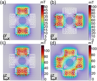 |
| | Fig. 8 (a) Magnetic field simulation results of the coil pairs in the Y direction (12 V). (b) Magnetic field simulation results of the coil pairs in the X direction(24 V). (c) Magnetic field simulation results of the coil pairs in the Z direction (36 V). (d) Magnetic field simulation results of the coil pair in the X–Z direction (24 V). | |
In addition, we compare the reported systems in Table 2, where the orthogonal coil drive system established by C. Chen et al. (2019),46 despite its low system complexity and cost, required constant changes in routing algorithms. S. Yu et al. (2019)47 and Q. Fu et al. (2018)35 used the three-axis Helmholtz coil as the driving system, which had high system operability and low system complexity, but the system cost is expensive. M. P. Kummer et al. (2010)48 and S Schuerle et al. (2013)49 and J Nam et al. (2018)50 all adopted multiple -degree of freedom drive systems, which required a plethora of coils. Moreover, due to the complex coupling behavior between magnetic fields, modeling and analysis are often required, so the feasibility of this system is relatively low. The results indicate that our system based on embedded development has lower complexity compared to the magnetic drive systems reported in Table 2. The use of keys for remote-control makes the system more operable. And the components we use greatly reduce system costs.
Table 2 A comparison of the feasibility of magnetic drive systems
| Coil type |
Study |
System complexity |
System costs |
System operability |
Magnetic field type |
| Air core type |
C. Chen et al. (2019) |
Low |
Low |
Low |
Oscillating |
| S. Yu et al. (2019) |
Low |
High |
High |
rotating |
| Q. Fu et al. (2018) |
Low |
High |
High |
rotating |
| Iron core type |
M. P. Kummer et al. |
High |
High |
Low |
Nonlinear |
| S. Schuerl et al. (2013) |
High |
High |
Low |
Nonlinear |
| J. Nam et al. (2018) |
High |
High |
Low |
Combinatorial |
3.3 Magnetic actuation and motion control of capsule microrobots
In human blood vessels, although the Reynolds number near the peak of the aortic root or cardiac systole is often greater than 2100, most of them are in a low Reynolds number environment under normal conditions. Meanwhile, on the micron scale, low environments typically dominate. Therefore, when the blood flow in the blood vessel is assumed to be at a low Reynolds number, the viscous force will dominate the targeted delivery of drugs, and the inertial force can be ignored. This means that if a continuous force is applied to the capsule microrobots through an external magnetic field, it will be driven forward continuously on the plane. It also means that the speed and direction of the capsule microrobots can be changed simply by changing the magnitude, direction and frequency of the magnetic field force. Since the spherical capsule microrobots are driven by a rotating magnetic field, when the magnetic field direction after the magnetization of the magnetic medium is aligned with the external magnetic field, the rotating magnetic field will drive the capsule microrobots to roll. The magnetic induction intensity B in capsule microrobots can be obtained by the following equation:where μ0 is the vacuum permeability, H is the external magnetic field strength, M is the magnetic field strength generated by the magnetization of the medium by H, and is the magnetic susceptibility. Magnetic objects in the rotating magnetic field are not only affected by the magnetic force but also by the magnetic torque. The magnetic force tends to make the object move along the large magnetic field gradient, and the magnetic torque tends to align the magnetization direction of the object with the direction of the external magnetic field. The magnetic force Fm and magnetic torque m of capsule microrobots can be determined by the following equation:where Vm is the volume of the capsule microrobots. Since the magnetic field in the coil wrapped area is a uniform field, the magnetic torque τm will dominate and the magnetic force Fm will be ignored.
According to the driving principle of capsule microrobots, Fig. 9(a) shows the experimental situation where a single capsule microrobot can be freely propelled along different trajectory directions under the control of a rotating magnetic field (see Video S2, ESI†). The ellipse in the figure represents the rotation direction of the rotating magnetic field, the black arrow represents the movement direction of the capsule microrobot, and the red arrow represents the movement trajectory of the capsule microrobot. The direction, size and frequency of the rotating magnetic field are all controlled by manually adjusting the duty cycle size and interruption time of the PWM wave. By adjusting the magnetic field, the capsule microrobots are able to roll flexibly in the operating area. In addition, when the direction of the rotating magnetic field changes according to the tangent of the unit circle, as shown in Fig. 9(b), the capsule microrobots can be driven on a circle-like track (rotation frequency 0.2 Hz, rotation angular speed 1.26 rad s−1) (see Video S3, ESI†). In order to realize the propulsion of capsule microrobots in this way, it is necessary to control the magnetic field components of the three axes in the magnetic actuation system, as follows:
| | Bx = λxB0![[thin space (1/6-em)]](https://www.rsc.org/images/entities/char_2009.gif) cos(2πf1t) cos(2πf1t) | (12) |
| | By = λyB0![[thin space (1/6-em)]](https://www.rsc.org/images/entities/char_2009.gif) cos(2πf1t) cos(2πf1t) | (13) |
| | Bz = B0![[thin space (1/6-em)]](https://www.rsc.org/images/entities/char_2009.gif) sin(2πf1t) sin(2πf1t) | (14) |
| |  | (16) |
where
λx and
λy are the magnetic field adjustment coefficients in the
X and
Y directions, respectively. The values can be finely adjusted by adjusting the duty cycle of the PWM wave, which is mainly used to control the rotation direction of the rotating magnetic field in the
x–
y plane. The angle is determined by
θ, and
f1 is the frequency of the rotating magnetic field. Based on this control method, arbitrary rolling and smooth steering of capsule microrobots on a plane are achieved. The experimental results show that the capsule microrobots can operate freely under the developed magnetic drive system, and the response delay time is almost 0.0 s.
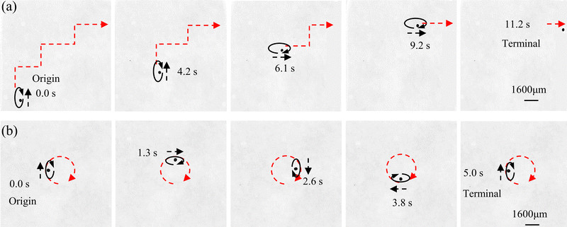 |
| | Fig. 9 (a and b) Time-shifted images of capsule microrobots in CaCl2 solution under a controlled rotating magnetic field. (a) Trapezoidal trajectory. (b) Circular trajectory. | |
3.4 Motion performance of capsule microrobots
Speed and targeting accuracy of capsule microrobots will be key factors for patients to receive effective treatment. To better simulate the motion performance of the capsule microrobots in blood vessels, the kinetic properties at different frequencies, field strengths and motion regimes are investigated. The capsule microrobots are dispersed in a square container full of CaCl2 solution, and the smooth PMMA plate is bonded by the epoxy resin to form the monolithic pattern of the container, which is driven under a rotating magnetic field (H(t) = HR [λx![[thin space (1/6-em)]](https://www.rsc.org/images/entities/char_2009.gif) cos(ωRt)ex + λy
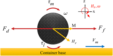
cos(ωRt)ex + λy![[thin space (1/6-em)]](https://www.rsc.org/images/entities/char_2009.gif) cos(ωRt)ey + sin(ωRt)ez]) in the X–Y plane. HR is the size of the rotating magnetic field, ωR is the angular frequency of the rotating magnetic field. The magnetic torque τm = μ0(m × HR) the capsule microrobots to roll at an average angular velocity ω. Fig. 10 shows the force of the capsule microrobots moving along the smooth plane driven by the x–z rotating magnetic field. The rotational motion of capsule microrobots not only generates the friction force forward Ff, but also the resistance force backward Fd and the liquid resistance moment τl.
cos(ωRt)ey + sin(ωRt)ez]) in the X–Y plane. HR is the size of the rotating magnetic field, ωR is the angular frequency of the rotating magnetic field. The magnetic torque τm = μ0(m × HR) the capsule microrobots to roll at an average angular velocity ω. Fig. 10 shows the force of the capsule microrobots moving along the smooth plane driven by the x–z rotating magnetic field. The rotational motion of capsule microrobots not only generates the friction force forward Ff, but also the resistance force backward Fd and the liquid resistance moment τl.
 |
| | Fig. 10 Force analysis of capsule microrobots on a smooth surface. | |
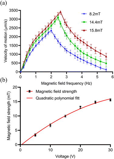
When approaching the bottom plane, the increase of the viscosity of the capsule microrobots on the solid surface will lead to the increase of the friction force, and the liquid resistance moment will be balanced by the magnetic torque τm. The unbalanced resistance in the forward direction is the fundamental cause of the rolling of the capsule microrobots on the substrate. And when the angular velocity ω(2πf) is lower than the out-of-step angular velocity ωs(2πfs), the capsule microrobots will rotate synchronously with the magnetic field and reach the peak at ωs. When ω is higher than the out-of-step angular velocity ωs, the capsule microrobots will no longer synchronize with the rotating magnetic field due to the sharp increase in the viscous drag moment. Fig. 11(a) shows the variation trend of the motion velocity of capsule microrobots under different magnetic field intensities and frequencies. When a certain magnetic field intensity is applied, the advance speed of the capsule microrobots will increase linearly with the increase of frequency. When the magnetic field strength is 8.2 mT (supply voltage 12 V), the out of step frequency of the capsule microrobots is 2 Hz (12.57 rad s−1) and reaches the maximum rolling speed of 2353 μm s−1. When the magnetic field strength is 14.4 mT (24 V), the out of step frequency of the capsule microrobots is 2.4 Hz (15.08 rad s−1) and reaches the maximum rolling speed of 3077 μm s−1. When the magnetic field strength is 16.3 mT (36 V), the out of step frequency of the capsule microrobots is 2.6 Hz (16.34 rad s−1) and reaches the maximum rolling speed of 3418 μm s−1. With the further increase of frequency (ω > ωs), the rolling speed of the capsule microrobots begin to decrease and the phenomenon of jitter appeared. It is worth noting that with the doubling of the input voltage of the coil, the intensity of the magnetic field and the out-of-step frequency of the capsule microrobots did not double, but tended to slow down with the increase of the voltage (Fig. 11(b)). The reason may be that the diameter of the coil affects the size of the magnetic field produced by the coil, which limits the threshold of the coil current and causes the coil to overheat. These results show that the capsule microrobot has a very high moving speed in a low Reynolds number environment, and can reach a moving speed of 800 μm s−1 at a low frequency of 0.4 Hz, and the speed can be continuously adjusted by controlling the frequency of the magnetic field. In addition, the strength of the magnetic field can be adjusted by voltage to accommodate liquid environments with different resistances.
 |
| | Fig. 11 (a) The relationship between the moving speed v and the driving frequency f of the capsule microrotor under a rotating magnetic field in the x–z plane. (b) The relationship between the strength of the magnetic field generated by a coil and the voltage in a control system at room temperature. | |
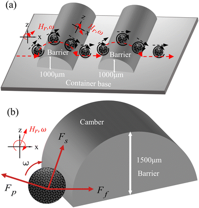
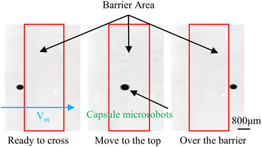
Meanwhile to further simulate the actual motion state of capsule microrobots in blood vessels, the laser sculpting technique and epoxy adhesive are used to construct simulated transport channels and obstacles on the basis of the vessel. The overall channel is M type, 2 mm wide and 90°–180° bends are set in the middle, continuous barrier height of 1000 μm and 30°–45° slope (Fig. 12(a)). From the force analysis during the barrier-crossing process of the capsule microrobots (Fig. 12(b)), it is known that rotation during its advancing process results in an uneven flow of fluid, which in turn leads to an increase in the pressure difference between the upper and lower pressure of the capsule microrobots during its movement. Therefore, under the joint action of the base friction Ff, the slope friction Fs, and the fluid pressure Fp, the capsule microrobots successfully crossed the obstacle. Fig. 13 and Fig. 14 respectively show the time-shift images of the capsule microrobots passing through the microchannel (see Video S4, ESI†) and successfully climbing over obstacles (see Video S5, ESI†) by rolling under the magnetic field of 14 mT and 2.4 Hz. In addition, as shown in Fig. 15, we also studied the influence of the magnetic powder content on the motion behavior of the capsule microrobots. As can be seen from the figure, with the increase of the magnetic powder content, the maximum forward speed, the fastest climbing speed and out-of-step frequency of the capsule microrobots all increased, but the increasing trend gradually slowed down. It is speculated that the magnetic powder content in the capsule microrobots of the current size has reached saturation. Therefore, controlling the magnetic powder content will effectively improve the motion behavior of the capsule microrobots. The experimental results show that the capsule microrobots can reach the destination accurately along the predetermined trajectory in the low Reynolds number environment, and has the ability to climb over a single large obstacle and continuously over multiple obstacles.
 |
| | Fig. 12 (a) The shape and size of the obstacle. (b) Force analysis of capsule microrobots during obstacle crossing (base friction Ff, slope friction Fs, and fluid pressure Fp). | |
 |
| | Fig. 13 Time-shifted images of capsule microrobots targeting delivery in simulated vascular microchannels. | |
 |
| | Fig. 14 Time-shifted images of capsule microrobots crossing obstacles. | |
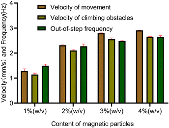 |
| | Fig. 15 Motion performance of capsule microrobots with different magnetic particle contents. | |
4 Conclusions
In this study, a hydrogel-based capsule microrobot is prepared from a three-coaxial microfluidic chip, with adjustable size ranging from 230 μm to 530 μm and driven by a developed three degree of freedom magnetic drive system. The formation mechanism of three phases: plug phase, bullet phase and droplet phase, which occur in the preparation of capsule microrobots is modeled and analyzed. The results show that the size and shape of the capsule microrobots can be easily controlled by adjusting the flow rate ratio of two phases in the microfluidic chip, and the prepared capsule microrobots have good surface quality and sensitive magnetic response. In addition, the developed three degrees of freedom magnetically driven system can produce an effective driving magnetic field. The simulation and analysis results show that the system can generate a uniform flux density in the operating area of 30 mm × 30 mm × 20 mm, and the magnetic field frequency is continuously adjustable from 0 to 111 Hz. Moreover, the coil drive circuit in the system is composed of MOSFET, IR2104 and other switch components, which greatly reduces the complexity and cost of the drive system. In order to verify the feasibility of targeted drug delivery of the capsule microrobot in the blood vessel, the motion process of the capsule microrobots in the blood vessel microchannel is simulated, the relationship between the motion performance of the capsule microrobots and the magnetic field is studied, and the dynamic performance of the capsule microrobot during the movement process is analyzed. The experimental results show that in the simulated vascular microchannel, the capsule microrobot can reach the destination along the predetermined trajectory, and has a high speed of 3077 μm s−1 and can continuously climb over a high 1000 μm 30°–45° slope obstacle under a magnetic field of 2.4 Hz and 14.4 mT. The capsule microrobots have the characteristics of easy preparation, low cost, sensitive response, and precise positioning, which is expected to become a new tool for intravascular drug targeting and expand the application of microrobots in the biomedical field. Future work will use the above methods for automatic navigation and drug delivery of capsule microrobots.
Conflicts of interest
There are no conflicts to declare.
Acknowledgements
We thank for the support from the Micro Nano Positioning Technology and Precision Operation Equipment Laboratory from Shanghai University and the National Key Research and Development Program of China (2018YFB1309200).
Notes and references
- S. H. Cross, B. G. Kaufman, R. J. Mentz, A. H. Kamal and H. J. Warraich, J. Am. Coll. Cardiol., 2019, 74, 1943–1946 CrossRef PubMed.
- W. Wang, Y. Liu, P. Ye, J. Liu, P. Yin, J. Qi, J. You, L. Lin, F. Wang, L. Wang, Y. Huo and M. Zhou, Lancet Reg. Health: West. Pac., 2022, 21, 100383 Search PubMed.
- A. N. Yawalkar, M. A. Pawar and P. R. Vavia, J. Drug Delivery Sci. Technol., 2022, 75, 103659 CrossRef CAS.
- N. H. Abu-Hamdeh, R. A. R. Bantan, F. Aalizadeh and A. Alimoradi, Alexandria Eng. J., 2020, 59, 4049–4062 CrossRef.
- H. Henrique Carline de Lima, G. Mansano Santos, C. Thiago Pereira da Silva, J. Calvi Mori, J. De Carvalho Rinaldi, R. Seki Kioshima Cotica, E. B. Tambourgi, M. Rogério Guilherme and A. Wellington Rinaldi, J. Mol. Liq., 2023, 372, 120709 CrossRef CAS.
- T. R. Hoare and D. S. Kohane, Polymer, 2008, 49, 1993–2007 CrossRef CAS.
- Z. Chen, S. Song, J. Ma, S. D. Ling, Y. D. Wang, T. T. Kong and J. H. Xu, Chem. Eng. Sci., 2022, 248, 103659 Search PubMed.
- P. N. Dave, P. M. Macwan and B. Kamaliya, Int. J. Biol. Macromol., 2023, 224, 358–369 CrossRef CAS PubMed.
- D. Zheng, A. Ramos-Sebastian, W. S. Jung and S. H. Kim, Composites, Part B, 2022, 230, 109551 CrossRef CAS.
- C. Wang, N. Chen, T. Yang, Q. Cheng, D. Wu, Y. Xiao, S. He and N. Song, J. Magn. Magn. Mater., 2023, 565, 170267 CrossRef CAS.
- L. He, R. Zheng, J. Min, F. Lu, C. Wu, Y. Zhi, S. Shan and H. Su, J. Magn. Magn. Mater., 2021, 517, 167394 CrossRef CAS.
- K. Hu, J. Sun, Z. Guo, P. Wang, Q. Chen, M. Ma and N. Gu, Adv. Mater., 2015, 27, 2507–2514 CrossRef CAS PubMed.
- S. A. Meenach, J. Z. Hilt and K. W. Anderson, Acta Biomater., 2010, 6, 1039–1046 CrossRef CAS PubMed.
- A. J. Moitoi and S. Shaw, Microvasc. Res., 2022, 139, 104262 CrossRef PubMed.
- D. Gong, J. Cai, N. Celi, L. Feng, Y. Jiang and D. Zhang, J. Magn. Magn. Mater., 2018, 468, 148–154 CrossRef CAS.
- F. Lin, J. Zheng, W. Guo, Z. Zhu, Z. Wang, B. Dong, C. Lin, B. Huang and B. Lu, Cellulose, 2019, 26, 6861–6877 CrossRef CAS.
- H. Li, G. Go, S. Y. Ko, J.-O. Park and S. Park, Smart Mater. Struct., 2016, 25, 027001 CrossRef.
- H. Thakar, S. M. Sebastian, S. Mandal, A. Pople, G. Agarwal and A. Srivastava, ACS Biomater. Sci. Eng., 2019, 5, 6320–6341 CrossRef CAS PubMed.
- G. Liu, J. Gao, H. Ai and X. Chen, Small, 2013, 9, 1533–1545 CrossRef CAS PubMed.
- W. Chen, Y. Wen, X. Fan, M. Sun, C. Tian, M. Yang and H. Xie, J. Mater. Chem. B, 2021, 9, 1030–1039 RSC.
- A. W. Mahoney and J. J. Abbott, Int. J. Rob. Res., 2015, 35, 129–147 CrossRef.
- H. Zhou, C. C. Mayorga-Martinez, S. Pane, L. Zhang and M. Pumera, ChemBioEng Rev., 2021, 121, 4999–5041 CrossRef CAS PubMed.
- M. Sendoh, K. Ishiyama, K. I. Arai, M. Jojo, F. Sato and H. Matsuki, IEEE Trans. Magn., 2002, 38, 3359–3361 CrossRef CAS.
- H. Shen, S. Cai, Z. Wang, Z. Ge and W. Yang, Mater. Des., 2023, 227, 111735 CrossRef CAS.
- E. Diller, J. Giltinan, G. Z. Lum, Z. Ye and M. Sitti, Int. J. Rob. Res., 2015, 35, 114–128 CrossRef.
- H. Ceylan, J. Giltinan, K. Kozielski and M. Sitti, Lab Chip, 2017, 17, 1705–1724 RSC.
- M. Mahmoodpour, M. Goharkhah and M. Ashjaee, J. Magn. Magn. Mater., 2020, 497, 166065 CrossRef CAS.
- A. A. Zafar, N. A. Shah and I. Khan, J. Magn. Magn. Mater., 2019, 477, 382–387 CrossRef.
- B. Tian and J. Liu, Int. J. Biol. Macromol., 2023, 235, 123902 CrossRef CAS PubMed.
- Y. He, J. Tang, Y. Hu, S. Yang, F. Xu, M. Zrínyi and Y. Mei Chen, Chem. Eng. J., 2023, 462, 142193 CrossRef CAS.
- Z. Li, Y. Li, C. Chen and Y. Cheng, J. Controlled Release, 2021, 335, 541–556 CrossRef CAS PubMed.
- Q. Liu, X. Ye, H. Wu and X. Zhang, Int. J. Mech. Sci., 2022, 215, 106963 CrossRef.
- W. Yang, Z. Wang, X. Wang, Y. Chen, Z. Ge and H. Yu, Sens. Actuators, B, 2023, 382, 133509 CrossRef CAS.
- Y. Chen, Y. Zhang, H. Li, J. Shen, F. Zhang, J. He, J. Lin, B. Wang, S. Niu, Z. Han and Z. Guo, Nano Today, 2023, 49, 101764 CrossRef CAS.
- Q. Fu, S. Zhang, S. Guo and J. Guo, Micromachines, 2018, 9, 641 CrossRef PubMed.
- Z. Cai, Q. Fu, S. Zhang, S. Guo, J. Guo, X. Zhang and C. Fan, IEEE Trans. Instrum. Meas., 2022, 71, 1–11 Search PubMed.
- D. Kim, H. Lee, S. Hyun Kwon, H. Choi and S. Park, Sens. Actuators, B, 2019, 289, 65–77 CrossRef CAS.
- H. Lee, H. Choi, M. Lee and S. Park, Biomed. Microdevices, 2018, 20, 1–9 CrossRef CAS PubMed.
- K. Enck, S. P. Rajan, J. Aleman, S. Castagno, E. Long, F. Khalil, A. R. Hall and E. C. Opara, Ann. Biomed. Eng., 2020, 48, 1103–1111 CrossRef PubMed.
- Z. Chen, S. Song, J. Ma, S. D. Ling, Y. D. Wang, T. T. Kong and J. H. Xu, Chem. Eng. Sci., 2022, 248, 117216 CrossRef CAS.
- E. Um, D.-S. Lee, H.-B. Pyo and J.-K. Park, Microfluid. Nanofluid., 2008, 5, 541–549 CrossRef.
- M.-H. Wu and W.-C. Pan, Microfluid. Nanofluid., 2010, 8, 823–835 CrossRef CAS.
- Y. Morimoto, W.-H. Tan and S. Takeuchi, Biomed. Microdevices, 2009, 11, 369–377 CrossRef PubMed.
- Q. Zhang, J. Chen and H. Gai, J. Mater. Sci., 2019, 54, 14905–14913 CrossRef CAS.
- H. Shieh, M. Saadatmand, M. Eskandari and D. Bastani, Sci. Rep., 2021, 11, 1565 CrossRef CAS PubMed.
- C. Chen, L. Chen, P. Wang, L.-F. Wu and T. Song, J. Magn. Magn. Mater., 2019, 479, 74–83 CrossRef CAS.
- S. Yu, N. Ma, H. Yu, H. Sun, X. Chang, Z. Wu, J. Deng, S. Zhao, W. Wang, G. Zhang, W. Zhang, Q. Zhao and T. Li, Nanomaterials, 2019, 9, 1672 CrossRef CAS PubMed.
-
M. P. Kummer, J. J. Abbott, B. E. Kratochvil, R. Borer, A. Sengul and B. J. Nelson, 2010 IEEE International Conference on Robotics and Automation, 1610–1616.
- S. Schuerle, S. Erni, M. Flink, B. E. Kratochvil and B. J. Nelson, IEEE Trans. Magn., 2013, 49, 321–330 Search PubMed.
- J. Nam, W. Lee, E. Jung and G. Jang, IEEE Trans. Ind. Electron., 2018, 65, 5673–5681 Search PubMed.
|
| This journal is © The Royal Society of Chemistry 2023 |
Click here to see how this site uses Cookies. View our privacy policy here.  ,
Hangkong
Ouyang
*,
Xiaoguang
Zheng
,
Chongwen
Qi
and
Li
Ma
*
,
Hangkong
Ouyang
*,
Xiaoguang
Zheng
,
Chongwen
Qi
and
Li
Ma
*


![[thin space (1/6-em)]](https://www.rsc.org/images/entities/char_2009.gif) cos(2πf1t)
cos(2πf1t)![[thin space (1/6-em)]](https://www.rsc.org/images/entities/char_2009.gif) cos(2πf1t)
cos(2πf1t)![[thin space (1/6-em)]](https://www.rsc.org/images/entities/char_2009.gif) sin(2πf1t)
sin(2πf1t)

![[thin space (1/6-em)]](https://www.rsc.org/images/entities/char_2009.gif) cos(ωRt)ex + λy
cos(ωRt)ex + λy![[thin space (1/6-em)]](https://www.rsc.org/images/entities/char_2009.gif) cos(ωRt)ey + sin(ωRt)ez]) in the X–Y plane. HR is the size of the rotating magnetic field, ωR is the angular frequency of the rotating magnetic field. The magnetic torque τm = μ0(m × HR) the capsule microrobots to roll at an average angular velocity ω. Fig. 10 shows the force of the capsule microrobots moving along the smooth plane driven by the x–z rotating magnetic field. The rotational motion of capsule microrobots not only generates the friction force forward Ff, but also the resistance force backward Fd and the liquid resistance moment τl.
cos(ωRt)ey + sin(ωRt)ez]) in the X–Y plane. HR is the size of the rotating magnetic field, ωR is the angular frequency of the rotating magnetic field. The magnetic torque τm = μ0(m × HR) the capsule microrobots to roll at an average angular velocity ω. Fig. 10 shows the force of the capsule microrobots moving along the smooth plane driven by the x–z rotating magnetic field. The rotational motion of capsule microrobots not only generates the friction force forward Ff, but also the resistance force backward Fd and the liquid resistance moment τl.


