 Open Access Article
Creative Commons Attribution 3.0 Unported Licence
Dissociative ionization and post-ionization alignment of aligned O2 in an intense femtosecond laser field
Shinichi
Fukahori
 ab,
Ayumi
Kubo
a and
Hirokazu
Hasegawa
 *ab
*ab
aDepartment of Integrated Sciences, Graduate School of Arts and Sciences, The University of Tokyo, 3-8-1 Komaba, Meguro-ku, Tokyo 153-8902, Japan. E-mail: chs36@mail.ecc.u-tokyo.ac.jp
bKomaba Institute for Science, Graduate School of Arts and Sciences, The University of Tokyo, 3-8-1 Komaba, Meguro-ku, Tokyo 153-8902, Japan
First published on 30th September 2024
Abstract
We examined dissociative ionization of O2 in an intense femtosecond laser field (782 nm, 120 fs, 4 × 10¹⁴ W cm−2) by recording the kinetic energy distribution of O+ emitted along the laser polarization direction as a function of the delay time between the pump pulse (9 × 10¹³ W cm−2) for the molecular alignment and the probe pulse for the dissociative ionization. We found the two distinct rotational revival patterns which are out-of-phase by π with each other in the kinetic energy distribution of O+. One of the patterns shows the dissociative ionization is enhanced when the O2 axis is parallel to the laser polarization direction, suggesting that the ionization is induced by the electron emission from the 3σg orbital. On the other hand, the other pattern shows that the dissociative ionization is enhanced when the O2 axis is perpendicular to the laser polarization direction, suggesting that the ionization is induced by the electron emission from the 1πu orbital. Because of the collection efficiency of the time-of-flight mass spectrometer, the enhancement of the O+ yield at the anti-alignment time delay indicates that the electron emission from the 1πu orbital is followed by the molecular alignment of O2+ in the course of the dissociation. We performed classical trajectory Monte-Carlo simulation of O2+ with the dissociation and rotational coordinates in the light-dressed potential to evaluate the effect of the post-ionization alignment by the probe pulse.
1 Introduction
When molecules are irradiated with an intense laser field, ionization is induced and the electronic states of the molecular ion are coupled to each other by the subsequent laser field.1,2 Although the bound electronic states of the molecular ion are created at the moment of the electron emission, dissociation of the molecular ion can be induced through the laser-induced electronic state coupling. For example, dissociative ionization of the simplest molecule, H2, in intense laser fields has been investigated extensively.3–12 Upon the ionization of H2, an electron is emitted from the 1σg orbital, resulting in the generation of the ground X 2Σ+g state, from which the dissociation does not occur. However, the X 2Σ+g state is coupled to the excited A 2Σ+u state by the subsequent laser field after the electron emission, leading to the dissociation. This mechanism of dissociation has been understood using the light-dressed potential picture8,10 and is known as processes such as “bond softening”4 and “above-threshold dissociation”.3Meanwhile, in the case of a many-electron system, it is possible that an electron is emitted from inner-valence orbitals upon ionization.13–19 Therefore, identification of the molecular orbital from which the electron is emitted is important to understand the ionization dynamics of molecules. The shape of the molecular orbital can be discussed on the basis of the tunnel ionization probability sensitively dependent on the angle between the molecular axis and the laser polarization axis.20–34 Previously, we examined the angle-dependent probability of the non-dissociative ionization of C2H2,28 NO,32 and H2O33,34 molecules in intense laser fields by recording the molecular ion yield as a function of the time delay between a pair of intense femtosecond laser pulses. In those experiments, the rotational wave packet of the target molecules was created through impulsive rotational Raman transition35–38 by the pump pulse while the molecule was ionized by the probe pulse, and the produced molecular ions were detected by a time-of-flight mass spectrometer (TOF-MS). Because ionization probability depends on the angle between the molecular axis and the polarization direction, i.e., the molecular alignment angle, the recorded ion yield varies depending on the time delay between the pump and probe pulses associated with the time evolution of the rotational wave packet. On the basis of a similar technique, the angle-dependent probability of the dissociative ionization of C2H2 was examined by the momentum imaging of the fragment ions.27,39
Dissociative ionization of O2 in intense laser fields has been examined extensively,40–44 because it is also a good example of the laser induced electronic state coupling in the molecular ion after the electron emission. The kinetic energy release (KER) spectra of O+ in the (1,0) dissociation (O2+ → O+ + O) exhibit distinct structures, suggesting a variety of dissociative channels. The electron configuration of an O2 molecule in the ground X 3Σ−g state is expressed as (1σg)2(1σu)2(2σg)2(2σu)2(3σg)2(1πu)4(1πg)2. When an electron is emitted from the highest occupied molecular orbital (HOMO), 1πg, the ground X 2Πg state of O2+ is created, and the ionization probability is found to be enhanced when θ is about 45°, where θ is the angle between the O2 molecular axis and the laser polarization direction, reflecting the shape of the 1πg orbital.22,24,31 However, the preparation of the deeply bound X 2Πg state has not been considered to be the major origin of the dissociation of O2+ in an intense near-infrared laser field.
On the other hand, when an electron is emitted from the HOMO−1, 1πu, in an intense laser field, the a 4Πu state of O2+ is created because the ionization energy (16.7 eV) to the quartet a 4Πu state is lower than that (17.7 eV) to the doublet A 2Πu state.45 Similarly, when an electron is emitted from the HOMO−2, 3σg, the b 4Σ−g state of O2+ is created. Previously, the momentum images of O+ produced in the dissociation processes from O2+ were examined on the basis of the light-dressed potential picture40 and the a 4Πu state of O2+ was found to be the major origin of the dissociation. These assignments with the a 4Πu state were further confirmed by examination of the dissociation of O2+ in intense laser fields using an O2+ ion beam source as a target sample.46,47 Meanwhile, from the molecular frame photoelectron angular distributions produced in a circularly polarized laser field,43 it was recently found that not only electron emission from the 1πu orbital but also electron emission from the 3σg orbital can result in dissociation.
The electron emission from the 1πu and 3σg orbitals can be distinguished if the delay dependence of the O+ yield associated with the time evolution of the rotational wave packet of O2 is examined by the pump–probe method as described above. However, in the experiment with the TOF-MS, a pinhole needs to be installed in front of a micro-channel plate (MCP) detector to obtain KER from TOF, indicating that this method may not be extended from the measurement of the molecular ion to that of the fragment ion in a KER-resolved manner. When the O2 axis is aligned along the TOF axis, the O+ fragment ion passes the pinhole and can be detected. On the other hand, when the O2 axis is anti-aligned, it is considered that the O+ ion does not pass the pinhole and cannot be detected. Thus, the recorded delay dependence of the O+ ions may represent only the molecular axis distribution rather than the angular dependence of the dissociative ionization probability, due to the collection efficiency of the detection system.
We solve this problem by using a 120-fs-long pulse as the probe. The O+ ions produced from anti-aligned O2 at the moment of ionization can be detected by the effect called post-ionization alignment (PIA), that is, the molecular alignment induced by the laser field after the ionization.48 In a previous study,42 the PIA was observed for the 25-fs-long pulse as the peak shift in the angular distribution of O+ towards the laser polarization direction when the laser-field intensity was increased. Therefore, the duration of 120 fs is sufficiently long to induce the PIA so that O+ passes the pinhole in the TOF-MS, and we can distinguish the electron emission from the 1πu and 3σg orbitals in the various dissociation channels. In this work, we investigate dissociative ionization of O2 on the basis of the angle-dependent ionization probability by recording the O+ fragment ion yield as a function of the pump–probe delay.
2 Methods
2.1 Experiment
A linearly polarized femtosecond laser pulse (782 nm, 120 fs, 10 mJ per pulse, 10 Hz) from a Ti:sapphire amplifier (α-10, BM Industries) was split into the pump and probe pulses by a Michelson interferometer. The delay time between the pump and probe pulses was controlled by a linear motorized stage located in the optical path of the probe pulse in the interferometer. The pump and probe pulses were focused on the supersonic molecular beam of O2 diluted in He (1%, 0.3 MPa) in a vacuum chamber equipped with a TOF-MS by a plano-convex lens (f = 200 mm). The space charge effect can securely be neglected due to the low concentration of O2 and the high ionization energy of the buffer He gas. The diameter and pulse energy of the pump pulse were adjusted by an iris. We recorded an image of the focal spot by a CMOS camera and the focal diameters of the pump and probe pulses were obtained as 80 μm and 47 μm, respectively. The polarization direction of the two pulses was set to be parallel to the TOF axis and the laser-field intensities at the focal point are estimated to be 9.3 × 10¹³ W cm−2 and 3.9 × 10¹⁴ W cm−2 for the pump and probe pulses, respectively. In the TOF-MS, an electrode with a pinhole diameter of 5 mm was located in front of a MCP detector so that only O+ ions emitted along the TOF axis were detected. The acceptance angles are estimated to be ±14° for the released kinetic energy of 1.0 eV and ±5.5° for 7.0 eV. The released kinetic energies were obtained from the difference in the TOF between the forward and backward emission of O+ and the static electric field strength applied by the electrodes in the TOF-MS.492.2 Classical trajectory simulation
The effect of the PIA induced by the probe pulse was examined by the classical trajectory Monte-Carlo (CTMC) simulation. The alignment angle distribution of O2+ in the a 4Πu or b 4Σ−g state with respect to the laser polarization direction was initially prepared at the time of the electron emission in the laser pulse on the basis of the angle-dependent ionization probability. The dissociation of O2+ was induced by the laser-induced electronic state coupling, and in this simulation, we only consider the dissociation channels in which only one electronic state is coupled to the initial a 4Πu or b 4Σ−g state, for simplicity. The change from the initial alignment angle distribution to the distribution after the dissociation was evaluated by the classical trajectory calculation incorporated with the light-dressed potential picture.In the CTMC simulation, the initial parameters at the time of the electron emission (t0) were chosen so that their distributions assumed as follows are reproduced. The initial parameters are t0, the initial internuclear distance of O2 (r0), the initial momentum along the molecular axis (p0), the initial polar and azimuthal angles of the O2+ molecular axis with respect to the laser polarization direction (θ0, φ0), and the initial angular momenta (Jθ0, Jφ0) conjugated to (θ0, φ0).
Before ionization, O2 is in the vibronic ground state X 3Σ−g (v = 0), suggesting that the Wigner distribution function50 can be given by the product of the distribution function of the internuclear distance r0 [Pv=0(r0)] and that of the momentum p0 [Pp(p0)]. In addition, we assumed the isotropic molecular axis distribution of O2 in a thermal ensemble. The ionization probability was calculated from the cycle-averaged ionization rate W(r0,θ0,t0) at t = t0, r = r0 and θ = θ0 obtained on the basis of the molecular Ammosov–Delone–Krainov (MO-ADK) theory.51 The expansion coefficients in the MO-ADK theory were set to be C1 = 2.04, C3 = 0.33, and C5 = 0.01 for the 1πu orbital and C0 = 3.05, C2 = 1.59, and C4 = 0.08 for the 3σg orbital.52 To calculate W(r0,θ0,t0), the ionization energy depending on the internuclear distance of O2, r, was taken to be the field-free potential energy obtained later in Fig. 6.
Firstly, t0 was chosen from the distribution according to the ionization rate averaged over r0 and θ0 as
 | (1) |
 | (2) |
Pθ(θ0;t0,r0)sin![[thin space (1/6-em)]](https://www.rsc.org/images/entities/char_2009.gif) θ0dθ0 = W(r0,θ0,t0)sin θ0dθ0 = W(r0,θ0,t0)sin![[thin space (1/6-em)]](https://www.rsc.org/images/entities/char_2009.gif) θ0dθ0, θ0dθ0, | (3) |
Using these initial conditions, we calculated the classical trajectory on the basis of the equation of motion (EOM) as42,53,54
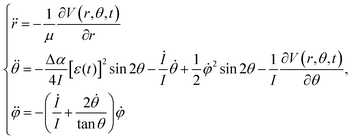 | (4) |
 | (5) |
 | (6) |
 defined as
 | (7) |
The non-adiabatic transition between the two dressed potentials was treated by the surface hopping with an ant-eater method.56 The probability of the non-adiabatic transition was estimated from the Landau–Zener formula. The alignment angle θ∞ after the dissociation was obtained as48
 | (8) |
3 Results and discussion
3.1 Delay dependence of the TOF spectrum of O+
Fig. 1(b) shows the recorded delay (τ) dependence of the TOF spectrum around a mass-to-charge ratio of 16, I(tTOF,τ). In Fig. 1(a), the TOF spectrum recorded when only the probe pulse is used is also shown. The central strong peak at tTOF = 4.027 μs is assigned to the O22+ dication produced by the double ionization of O2 and the delay dependence of the O22+ yield, as well as that of the O2+ yield,31 is not discussed in this paper. The other peaks are assigned to the O+ fragment ion and the released kinetic energy EKER is also shown in Fig. 1 on the right axis. The peaks in the energy range of EKER = 0.05–3.5 eV are assigned to O+ produced in the (1,0) dissociation (O2+ → O+ + O), while the peaks in the higher energy range are O+ produced in the (1,1) dissociation (O22+ → O+ + O+).40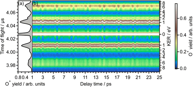 | ||
| Fig. 1 (a) TOF spectrum for the mass-to-charge ratio of 16 (O+), obtained only by probe pulse. (b) Delay dependence of the TOF spectrum. | ||
In the recorded delay dependence of the TOF spectrum of O+, the periodic yield modulation can be seen as a function of the delay time between the pump and probe pulses. As discussed later in Section 3.2, this periodic modulation originated from the time evolution of the rotational wave packet of O2 created by the pump pulse. In particular, for the peak in the range of EKER = 0.5–1.70 eV, the released kinetic energy seems to increase and decrease. However, the kinetic energy may not be varied by the rotational motion of O2, suggesting that this peak consists of the low energy component and the high energy component whose rotational revival patterns are out-of-phase with each other.
3.2 Fourier transform of the delay-dependent TOF spectrum of O+
Fig. 2(b) shows the Fourier transform (FT), Ĩ(tTOF,![[small nu, Greek, tilde]](https://www.rsc.org/images/entities/i_char_e0e1.gif) ), of the delay-dependent TOF spectrum, I(tTOF,τ), [Fig. 1(b)] with respect to the delay, τ. The FT spectrum exhibits the peaks at the wavenumbers of
), of the delay-dependent TOF spectrum, I(tTOF,τ), [Fig. 1(b)] with respect to the delay, τ. The FT spectrum exhibits the peaks at the wavenumbers of ![[small nu, Greek, tilde]](https://www.rsc.org/images/entities/i_char_e0e1.gif) = 10B0, 18B0, 26B0, 34B0, 42B0, 50B0, where B0 = 1.43767638 cm−1 is the rotational constant of O2 in the vibrational ground level of X 3Σ−g.57 These peaks are assigned to be the energy difference S(N) = (4N + 6)B0 between the two rotational levels of O2 whose rotational angular momentum quantum numbers N differ by 2 (ΔN = 2). Due to the nuclear-spin statistics, N takes only an odd value. Therefore, these peaks in the FT spectrum mean that the yield modulation observed in Fig. 1(b) originates from the time evolution of the rotational wave packet of O2. Moreover, the FT spectrum exhibits the peaks at
= 10B0, 18B0, 26B0, 34B0, 42B0, 50B0, where B0 = 1.43767638 cm−1 is the rotational constant of O2 in the vibrational ground level of X 3Σ−g.57 These peaks are assigned to be the energy difference S(N) = (4N + 6)B0 between the two rotational levels of O2 whose rotational angular momentum quantum numbers N differ by 2 (ΔN = 2). Due to the nuclear-spin statistics, N takes only an odd value. Therefore, these peaks in the FT spectrum mean that the yield modulation observed in Fig. 1(b) originates from the time evolution of the rotational wave packet of O2. Moreover, the FT spectrum exhibits the peaks at ![[small nu, Greek, tilde]](https://www.rsc.org/images/entities/i_char_e0e1.gif) = 28B0 and 44B0, which are assigned to be the energy difference U(N) = (8N + 20)B0 between the two rotational levels of O2 with ΔN = 4.
= 28B0 and 44B0, which are assigned to be the energy difference U(N) = (8N + 20)B0 between the two rotational levels of O2 with ΔN = 4.
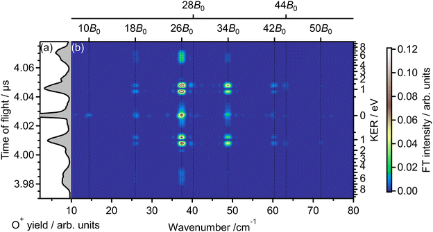 | ||
| Fig. 2 (a) TOF spectrum for a mass-to-charge ratio of 16 (O+), obtained only by probe pulse. The same as in Fig. 1(a). (b) Fourier transform of the delay-dependent TOF spectrum. | ||
In Fig. 3(a), the delay-integrated TOF spectrum Ĩ0(tTOF) is obtained as
 | (9) |
 | (10) |
![[small nu, Greek, tilde]](https://www.rsc.org/images/entities/i_char_e0e1.gif) is set to be the typical frequency resolution of the FT, 1/(τf − τi) = 1.39 cm−1. The frequency-integrated TOF spectrum Ĩ2(tTOF) exhibits the different spectral shape from the delay-integrated TOF spectrum. For example, the peak at EKER = 1.03 eV in Fig. 3(a) is divided into two peaks at EKER = 0.84 and 1.32 eV in Fig. 3(b). The frequency-integrated TOF spectrum Ĩ4(tTOF) is also obtained as
is set to be the typical frequency resolution of the FT, 1/(τf − τi) = 1.39 cm−1. The frequency-integrated TOF spectrum Ĩ2(tTOF) exhibits the different spectral shape from the delay-integrated TOF spectrum. For example, the peak at EKER = 1.03 eV in Fig. 3(a) is divided into two peaks at EKER = 0.84 and 1.32 eV in Fig. 3(b). The frequency-integrated TOF spectrum Ĩ4(tTOF) is also obtained as | (11) |
 | (12) |
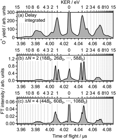 | ||
| Fig. 3 (a) Delay-integrated TOF spectrum. (b) Frequency-integrated TOF spectrum at ΔN = 2. (c) Frequency-integrated TOF spectrum at ΔN = 4. | ||
3.3 Delay dependence of O+ yield for (1,0) dissociation
![[thin space (1/6-em)]](https://www.rsc.org/images/entities/char_2009.gif) θ〉〉 of cos2
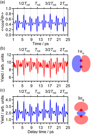
θ〉〉 of cos2![[thin space (1/6-em)]](https://www.rsc.org/images/entities/char_2009.gif) θ as a function of time t where θ is the alignment angle of the O2 axis with respect to the laser polarization direction and the expectation value is averaged over the initial rotational state distribution at 7.5 K. The estimation of the rotational temperature of 7.5 K will be discussed later in Section 3.3.2. When the O2 axis is aligned along the laser polarization direction, 〈〈cos2
θ as a function of time t where θ is the alignment angle of the O2 axis with respect to the laser polarization direction and the expectation value is averaged over the initial rotational state distribution at 7.5 K. The estimation of the rotational temperature of 7.5 K will be discussed later in Section 3.3.2. When the O2 axis is aligned along the laser polarization direction, 〈〈cos2![[thin space (1/6-em)]](https://www.rsc.org/images/entities/char_2009.gif) θ〉〉 becomes close to 1, while when the O2 axis is anti-aligned, 〈〈cos2
θ〉〉 becomes close to 1, while when the O2 axis is anti-aligned, 〈〈cos2![[thin space (1/6-em)]](https://www.rsc.org/images/entities/char_2009.gif) θ〉〉 becomes close to 0. We found that the experimental O+ yield is out-of-phase with 〈〈cos2
θ〉〉 becomes close to 0. We found that the experimental O+ yield is out-of-phase with 〈〈cos2![[thin space (1/6-em)]](https://www.rsc.org/images/entities/char_2009.gif) θ〉〉(t). The O+ yield increases when the O2 axis is anti-aligned with respect to the laser polarization direction. This result suggests that O+ in the energy range I is produced when an electron is emitted from the 1πu orbital.
θ〉〉(t). The O+ yield increases when the O2 axis is anti-aligned with respect to the laser polarization direction. This result suggests that O+ in the energy range I is produced when an electron is emitted from the 1πu orbital.
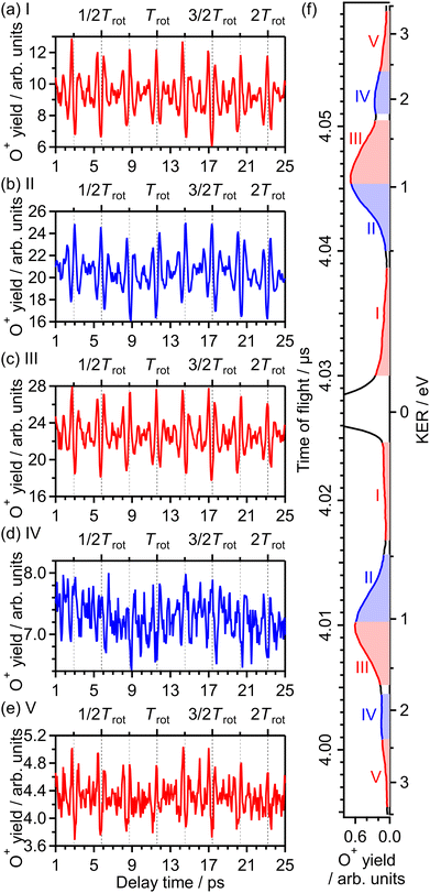 | ||
| Fig. 4 Recorded O+ yields as a function of delay time in the energy ranges (a) I, (b) II, (c) III, (d) IV and (e) V. (f) TOF spectrum obtained only by the probe pulse [same as Fig. 1(a)] with the labels of the energy ranges I, II, III, IV and V. | ||
We also calculated the yield of ionization corresponding to the electron emission from the 1πu orbital as a function of the pump–probe delay on the basis of the MO-ADK theory as in ref. 32. The delay dependence of the calculated ionization yield is shown in Fig. 5(b) and the yield increases when 〈〈cos2![[thin space (1/6-em)]](https://www.rsc.org/images/entities/char_2009.gif) θ〉〉 decreases in Fig. 5(a). Therefore, it is confirmed that the observed revival pattern in the energy range I [Fig. 4(a)] which is out-of-phase with 〈〈cos2
θ〉〉 decreases in Fig. 5(a). Therefore, it is confirmed that the observed revival pattern in the energy range I [Fig. 4(a)] which is out-of-phase with 〈〈cos2![[thin space (1/6-em)]](https://www.rsc.org/images/entities/char_2009.gif) θ〉〉(t) represents the electron emission from the 1πu orbital.
θ〉〉(t) represents the electron emission from the 1πu orbital.
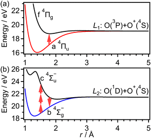
As discussed in the introduction, the a 4Πu state is considered to be created at the moment of the electron emission from the 1πu orbital. The lowest energy range I has been assigned to O+ produced in the bond softening associated with f 4Πg–a 4Πu one-photon crossing followed by the dissociation into the dissociation limit called L1 as41,46,47
 | (13) |
![[thin space (1/6-em)]](https://www.rsc.org/images/entities/char_2009.gif) θ〉〉(t) shown in Fig. 5(a). This result means that the O+ yield increases when the O2 axis is aligned along the laser polarization direction and suggests that O+ in the energy range II is produced when an electron is emitted from the 3σg orbital.
θ〉〉(t) shown in Fig. 5(a). This result means that the O+ yield increases when the O2 axis is aligned along the laser polarization direction and suggests that O+ in the energy range II is produced when an electron is emitted from the 3σg orbital.
The O+ yield calculated on the basis of the MO-ADK theory for the 3σg orbital is shown in Fig. 5(c). We found that the rotational revival pattern in the calculated O+ yield agrees well with that in the experimental O+ yield and confirmed that the energy range II is associated with the electron emission from the 3σg orbital. We note that the pump and probe laser-field intensities of 3.3 × 10¹³ W cm−2 and 1.4 × 10¹⁴ W cm−2, respectively, and the rotational temperature of 7.5 K are adopted for the calculation so that the discrepancy between the calculated O+ yield shown in Fig. 5(c) and the observed O+ yield shown in Fig. 4(b) is minimized.33
As discussed in the introduction, the b 4Σ−g state is considered to be created at the moment of the electron emission from the 3σg orbital. The O+ ions in the range of EKER = 0.50–1.04 eV can be generated by the dissociation of O2+ into the dissociation limit called L2 by the net-two photon absorption from the b 4Σ−g state. Indeed, when the vibrational levels of v+ = 0 and 1 in b 4Σ−g of O2+ are prepared at the moment of the electron emission, the absorption of two 782-nm-wavelength photons (1.59 eV) results in EKER = 0.64 and 0.79 eV, respectively, obtained from the ionization energies (18.17 eV for v+ = 0 and 18.31 eV for v+ = 1)61 and the energy of the L2 limit (20.70 eV).62 We consider that the energy range II can be assigned to O+ produced in the net-two photon dissociation into the L2 limit associated with c 4Σ−u–b 4Σ−g three-photon and one-photon crossings as
 | (14) |
![[thin space (1/6-em)]](https://www.rsc.org/images/entities/char_2009.gif) θ〉〉(t) shown in Fig. 5(a), while in-phase with that in the lowest energy range I. This means that O+ in this energy range III is produced when an electron is emitted from the 1πu orbital, that is, the ionization to the a 4Πu state. Thus, the peak at EKER = 1.03 eV is composed of the two different ionization pathways to the a 4Πu and b 4Σ−g states, resulting in the increase and decrease in EKER shown in Fig. 1(b).
θ〉〉(t) shown in Fig. 5(a), while in-phase with that in the lowest energy range I. This means that O+ in this energy range III is produced when an electron is emitted from the 1πu orbital, that is, the ionization to the a 4Πu state. Thus, the peak at EKER = 1.03 eV is composed of the two different ionization pathways to the a 4Πu and b 4Σ−g states, resulting in the increase and decrease in EKER shown in Fig. 1(b).
In previous studies,40,42,46 many assignments are proposed as the dissociation pathways in this energy range of EKER = 1.04–1.70 eV from the a 4Πu state, which agrees with the rotational revival pattern observed in Fig. 4(c). One of the candidates of the dissociation pathway is two photon excitation to the 1 4Σ+u state followed by the dissociation into the L1 limit.42,46 This pathway corresponds to the above-threshold dissociation (ATD) of the energy range I. Indeed, the energy difference between the ranges I and III is close to the one photon energy (1.59 eV). On the other hand, direct or sequential three photon excitation to the 2 4Πg state followed by the dissociation into the L2 limit is also known as a possible candidate.40,46
![[thin space (1/6-em)]](https://www.rsc.org/images/entities/char_2009.gif) θ〉〉(t) shown in Fig. 5(a) and that in the energy range II. This means that O+ in this energy range IV is produced when an electron is emitted from the 3σg orbital, that is, the ionization to the b 4Σ−g state.
θ〉〉(t) shown in Fig. 5(a) and that in the energy range II. This means that O+ in this energy range IV is produced when an electron is emitted from the 3σg orbital, that is, the ionization to the b 4Σ−g state.
Considering that the energy difference between the ranges II (0.50–1.04 eV) and IV (1.80–2.40 eV) is close to the one photon energy, the energy range IV can be assigned to the ATD of the range II. In other words, the dissociation into the L2 limit is followed by net-three photon absorption from the b 4Σ−g state. This process is achieved when the one photon emission does not occur in Fig. 6(b), that is, nonadiabatic transition at c 4Σ−u–b 4Σ−g one-photon crossing in the light-dressed potential picture. Therefore, we assign this energy range IV to the three-photon ATD as
 | (15) |
In order to evaluate the similarity in the delay dependence of the O+ yield in the two different energy ranges X1 and X2, we obtain the correlation coefficient as
 | (16) |
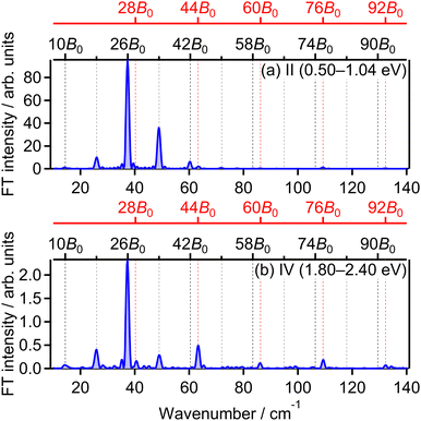
![[small nu, Greek, tilde]](https://www.rsc.org/images/entities/i_char_e0e1.gif) = 28B0, 44B0, 60B0, 76B0 and 92B0 which are assigned to ΔN = 4 components are found to be enhanced for the energy range IV. These ΔN = 4 frequencies in the energy range IV are the origins of the difference from the range II and the difference between the two FT spectra will be discussed in Section 3.4.2.
= 28B0, 44B0, 60B0, 76B0 and 92B0 which are assigned to ΔN = 4 components are found to be enhanced for the energy range IV. These ΔN = 4 frequencies in the energy range IV are the origins of the difference from the range II and the difference between the two FT spectra will be discussed in Section 3.4.2.
![[thin space (1/6-em)]](https://www.rsc.org/images/entities/char_2009.gif) θ〉〉(t) shown in Fig. 5(a) while in-phase with those in the energy ranges I and III. This means that O+ in this energy range V is produced when an electron is emitted from the 1πu orbital, that is, the ionization to the a 4Πu state. The energy difference between the ranges III (1.04–1.70 eV) and V (2.40–3.40 eV) is close to the one photon energy, indicating that the energy range V can be assigned to the higher-order ATD of the ranges I and III. We note that no assignments of this highest energy range V have been reported in previous studies.
θ〉〉(t) shown in Fig. 5(a) while in-phase with those in the energy ranges I and III. This means that O+ in this energy range V is produced when an electron is emitted from the 1πu orbital, that is, the ionization to the a 4Πu state. The energy difference between the ranges III (1.04–1.70 eV) and V (2.40–3.40 eV) is close to the one photon energy, indicating that the energy range V can be assigned to the higher-order ATD of the ranges I and III. We note that no assignments of this highest energy range V have been reported in previous studies.
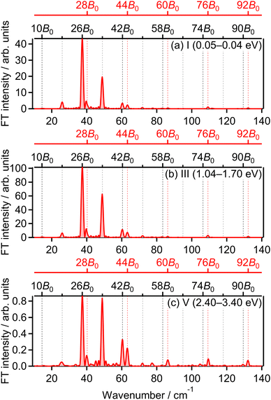
The correlation coefficients for the electron emission from the 1πu orbital are obtained as CI,III = 97% and CI,V = 80%. As seen in Fig. 4(a) and (c), the delay dependence of the O+ yield in the energy range III is very similar to that in the range I. On the other hand, the delay dependence of the O+ yield in the energy range V shown in Fig. 4(e) is slightly different from that in the range I. Fig. 8(a)–(c) show the FT spectra of the delay-dependent O+ yield in the energy range I, YI(τ), that in the range III, YIII(τ), and that in the range V, YV(τ), respectively. Similarly to the case for the electron emission from the 3σg orbital, the peaks assigned to the ΔN = 4 components are found to be enhanced only for the energy range V.
3.4 Effects of post-ionization alignment
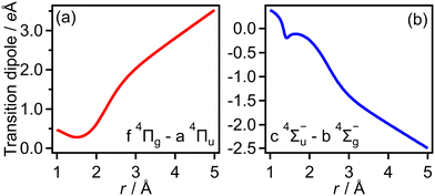
The transition dipole moment between the f 4Πg and a 4Πu states was calculated as a function of r as shown in Appendix B and is parallel to the O2+ axis. We also calculated the polarizabilities, α‖ and α⊥, of O2+ in the a 4Πu state as a function of r by the finite-element method as shown in Appendix B. On the basis of the model suggested in ref. 48,  was obtained as
  and α⊥(r) was obtained as a constant value of α⊥(r) = 5.94 a.u., where re = 1.40 Å is the equilibrium internuclear distance of O2+ in the a 4Πu state and a0 is the Bohr radius. In this calculation, the same values were used as the polarizabilities of O2+ in the f 4Πg state as discussed in Appendix B.
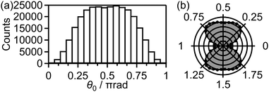
Fig. 9(a) shows the distribution of the initial alignment angle (θ0) at the moment of the electron emission from the 1πu orbital in the CTMC simulation in which 3 × 10⁵ trajectories were calculated. The corresponding angle-dependent ionization probability shown in Fig. 9(b) agrees with the shape of the 1πu orbital shown in the inset of Fig. 5(b). This means that the O2 axis at the moment of the electron emission from the 1πu orbital is anti-aligned with respect to the laser polarization direction. We confirmed that the obtained angle-dependent ionization probability well reproduces the angular dependence of the ionization rate in the MO-ADK theory as shown in Fig. 9(b).
Among all the trajectories, the dissociation occurs for around 1 × 10⁴ trajectories. Fig. 10(a) shows the correlation between θ0 at the moment of electron emission and θ∞ after dissociation for the dissociation trajectories. The effect of the PIA can be discussed on the basis of this correlation map. If the classical trajectories are plotted as dots on the diagonal line θ∞ = θ0, the effect of the PIA can be neglected. However, Fig. 10(a) exhibits the tendency of θ∞ < θ0 (θ0 < π/2) or θ∞ > θ0 (θ0 > π/2), indicating that the PIA is induced by the laser field. For example, although θ0 is initially 0.3π, major trajectories resulted in θ∞ close to 0, that is, O+ is emitted along the laser polarization direction. The distributions of θ0 and θ∞ for the dissociation trajectories are also shown in Fig. 10(b) and (c), respectively. The θ0 distribution exhibits peaks at 0.3π and 0.7π while the θ∞ distribution exhibits peaks at 0 and π. Therefore, we confirm the effect of PIA for the energy range I.
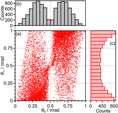 | ||
| Fig. 10 (a) Correlation between θ0 and θ∞, (b) the θ0 distribution and (c) the θ∞ distribution for bond softening (energy range I). | ||
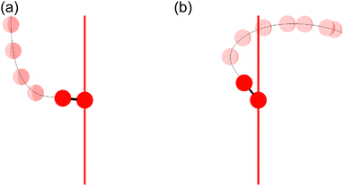
Fig. 11(a) shows one of the classical trajectories for which O+ is emitted along the laser polarization direction though the O2 axis is anti-aligned at the moment of the electron emission. On the other hand, Fig. 11(b) shows one of the classical trajectories for which the O2+ axis rotates further by strong torque induced by the laser field so that O+ is not emitted along the laser polarization direction. This trajectory resulted in the broad distribution over θ∞ > θ0 (θ0 < π/2) in Fig. 10(a).
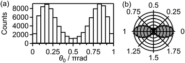
We calculated 1 × 10⁵ trajectories and the distribution of the initial alignment angle (θ0) at the moment of the electron emission is shown in Fig. 12(a). The corresponding angle-dependent ionization probability shown in Fig. 12(b) agrees with the shape of the 3σg orbital shown in the inset of Fig. 5(c). This means that the O2 axis at the moment of the electron emission from the 3σg orbital is aligned along the laser polarization direction.
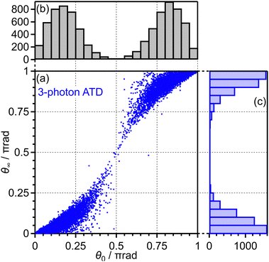
Among these 1 × 10⁵ trajectories, 8 × 10³ trajectories lead to the net-two photon process and other 8 × 10³ trajectories lead to the three-photon ATD. Fig. 13(a) shows the angular correlation map for the net-two photon process [eqn (14)]. The correlation map exhibits the tendency of θ∞ < θ0 (θ0 < π/2) or θ∞ > θ0 (θ0 > π/2), suggesting that the O2+ axis is more aligned along the laser polarization direction by the PIA effect in the energy range II. On the other hand, Fig. 14(a) shows the correlation map for the three-photon ATD [eqn (15)]. Although the major classical trajectories resulted in θ∞ < θ0 (θ0 < π/2) or θ∞ > θ0 (θ0 > π/2) also for the three-photon ATD, θ∞ becomes closer to θ0 than that for the net-two photon dissociation. The change in the O2+ axis direction in the energy range IV is considered to be less than that in the energy range II. Therefore, the extent of the PIA depends on the dissociation channels and the θ∞ distribution, which corresponds to the angular distribution of O+, can be different even though an electron is emitted from the same 3σg orbital in both of the channels. We consider that this difference in the PIA originates from the difference in the velocity of the dissociation and results in the difference in the FT spectra discussed in Section 3.3.4. Thus, when the PIA effect is small, higher ΔN components appear in the delay dependence of the O+ yield, reflecting the time evolution of the molecular axis distribution of O2 rather than the angle-dependent ionization probability.
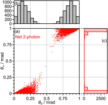 | ||
| Fig. 13 (a) Correlation between θ0 and θ∞, (b) the θ0 distribution and (c) the θ∞ distribution for net-two photon dissociation (energy range II). | ||
3.5 Delay dependence of O+ yield for (1,1) dissociation
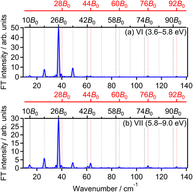
As seen in Fig. 1(b), the yield of O+ produced in the (1,1) dissociation exhibits the periodic increase and decrease as a function of time associated with the time evolution of the rotational wave packet of O2. Fig. 15(a) shows the O+ yield YVI(τ) in the energy range VI (EKER = 3.60–5.80 eV) which is a lower energy side of the (1,1) dissociation as shown in Fig. 15(c). The observed rotational revival pattern in the energy range VI is found to be in-phase with both of 〈〈cos2![[thin space (1/6-em)]](https://www.rsc.org/images/entities/char_2009.gif) θ〉〉(t) shown in Fig. 5(a) and that in the energy ranges II and VI. Similarly, Fig. 15(b) shows the O+ yield YVII(τ) in the energy range VII (EKER = 5.80–9.00 eV) which is a higher energy side of the (1,1) dissociation as shown in Fig. 15(c). The observed rotational revival pattern in the energy range VII is found to be also in-phase with 〈〈cos2
θ〉〉(t) shown in Fig. 5(a) and that in the energy ranges II and VI. Similarly, Fig. 15(b) shows the O+ yield YVII(τ) in the energy range VII (EKER = 5.80–9.00 eV) which is a higher energy side of the (1,1) dissociation as shown in Fig. 15(c). The observed rotational revival pattern in the energy range VII is found to be also in-phase with 〈〈cos2![[thin space (1/6-em)]](https://www.rsc.org/images/entities/char_2009.gif) θ〉〉(t). These results indicate that O+ in the (1,1) dissociation is produced when at least one of two electrons is emitted from the 3σg orbital. It is also possible that, because the (1,1) dissociation rapidly proceeds, the recorded delay dependence represents the axis distribution of O2 rather than the angular dependence of the ionization probability due to the pinhole located in front of the MCP detector.
θ〉〉(t). These results indicate that O+ in the (1,1) dissociation is produced when at least one of two electrons is emitted from the 3σg orbital. It is also possible that, because the (1,1) dissociation rapidly proceeds, the recorded delay dependence represents the axis distribution of O2 rather than the angular dependence of the ionization probability due to the pinhole located in front of the MCP detector.
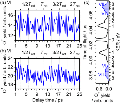 | ||
| Fig. 15 Recorded O+ yields as a function of delay time in the energy ranges (a) VI and (b) VII. (c) TOF spectrum obtained only by the probe pulse [same as in Fig. 1(a)] with the labels of the energy ranges VI and VII. | ||
The correlation coefficient CII,VI is found to be 87%, suggesting that the (1,1) dissociation in the energy range VI exhibits a similar character to the (1,0) dissociation in the energy range II. On the other hand, CII,VII is found to be 69%, indicating that the delay dependence of the O+ yield in the energy range VII is different from that in the range II. Fig. 16(a) and (b) show the FT spectrum of the delay dependence the O+ yield in the energy range VI, YVI(τ), and that in the range VII, YVII(τ), respectively. The peaks assigned to ΔN = 4 components are found to be enhanced for the energy range VII.
On the basis of previous studies on one-photon double ionization of O263,64 and double ionization of O2 in intense laser fields,65,66 the peak at EKER = 7 eV in the energy range VII can be assigned to the dissociation of O22+ in the W3Δu state. The major electron configuration of the W3Δu state is 1πu−11πg−1 (ref. 65) and the electron may not be emitted from the 3σg orbital. This means that the observed delay dependence of the O+ yield in the energy range VII originates not from the angle-dependent ionization probability but from the O2 axis distribution itself at the moment of the electron emission because the dissociation rapidly proceeds and the PIA effect for the double ionization is small at the current laser-field intensity.48
Meanwhile, in the previous studies on double ionization of O2 in intense sub-10-fs laser fields,65,66 no O+ signal was found in the energy range VI. In addition, in the previous studies on one-photon double ionization of O2,63,64 no assignment for direct dissociation from O22+ was proposed for the O+ signal in the energy range VI. In ref. 40, the TOF spectrum of O+ was recorded under a similar experimental condition with the laser temporal duration of 100 fs, and the O+ signal in the energy range VI was observed. Therefore, O+ in the energy range VI is produced only when the pulse duration is much longer than 10 fs, suggesting that O+ originates from enhance ionization67 associated with elongation of the O2+ internuclear distance. From the similarity in the delay dependence of the O+ yield to that in the energy range II, we consider that the enhanced ionization occurs in the course of the net-two photon dissociation [eqn (14)] after the electron emission from the 3σg orbital.
4 Conclusions
In summary, we examined the dissociative ionization dynamics of O2 molecules, by recording the delay-dependent O+ fragment ion yields associated with the time evolution of the rotational wave packet of O2 created by the pump laser pulse. From the recorded rotational revival patterns, we securely revealed that an electron is emitted from the 1πu orbital in the released kinetic energy ranges I (0.05–0.40 eV), III (1.04–1.70 eV) and V (2.40–3.40 eV), and from the 3σg orbital in the energy ranges II (0.50–1.04 eV) and IV (1.80–2.40 eV). The observed released kinetic energy distribution is well understood on the basis of the above-threshold dissociation structure associated with the electron emission from the 1πu and 3σg orbitals.Due to the experimental configuration, only the O+ fragment ion emitted along the laser polarization direction can be detected in this experiment. However, we observed the yield enhancement of O+ emitted from the anti-aligned O2 associated with the electron emission from the 1πu orbital. This means that the post-ionization alignment (PIA) of the O2+ molecular axis is induced by the probe pulse in the course of dissociation. We estimated the effect of the PIA of the O2+ axis induced by the probe pulse by performing the classical trajectory Monte-Carlo simulation incorporating the light-dressed potential picture. For the energy range I, which is assigned to the bond-softening type dissociation associated with the f 4Πg–a 4Πu one-photon crossing, we confirmed that the PIA is induced effectively so that the O+ fragment ion is emitted along the laser polarization direction.
We also performed the simulation for the electron emission from the 3σg orbital, and found that the effect of the PIA is less effective in the three-photon above-threshold dissociation (energy range IV) than in the net-two photon dissociation (energy range II) associated with the c 4Σ−u–b 4Σ−g three-photon and one-photon crossings. This result indicates that not only the angle-dependent ionization probability but also the dissociation dynamics can be encoded in the delay-dependent fragment ion yield recorded by the pump–probe measurement.
Author contributions
Shinichi Fukahori: methodology, investigation, formal analysis, software, writing – original draft, funding acquisition. Ayumi Kubo: investigation, data curation, formal analysis. Hirokazu Hasegawa: conceptualization, methodology, writing review & editing, supervision, project administration, funding acquisition.Data availability
Data for this article, including the delay dependence of the TOF spectrum recorded experimentally, the initial conditions and the results of the CTMC simulations, and the input and output files for the quantum chemical calculations by the GAMESS, are available at Zenodo at https://doi.org/10.5281/zenodo.12776677.Conflicts of interest
There are no conflicts to declare.Appendices
A Initial conditions in the CTMC simulation
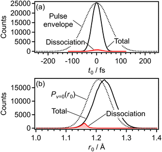
Fig. 17(a) shows the distribution of t0 for all the 3 × 10⁵ trajectories in the CTMC simulation for the electron emission from the 1πu orbital (Section 3.4.1). Because of the nonlinearity of the ionization probability with respect to the laser electric field, the width of the t0 distribution is narrower than that of the envelope of the laser electric field. The dissociation is defined to occur when r reaches 4 Å in the calculated trajectory and the t0 distribution of the dissociation trajectories are also shown in Fig. 17(a). On the other hand, Fig. 17(b) shows the distribution of the initial internuclear distance (r0) at the moment of the electron emission for all the 3 × 10⁵ trajectories. Compared with the Wigner distribution Pv=0(r0), the r0 distribution is shifted towards the longer internuclear distance because the ionization energy decreases as r becomes larger (r < 1.4 Å) [Fig. 6(a)]. However, the dissociation is found to occur only in r0 < 1.2 Å as shown in Fig. 17(b) and we solved the EOM (4) only when r0 < 1.25 Å in this calculation. On the other hand, in the CTMC simulation for the electron emission from the 3σg orbital (Section 3.4.2), we solved the EOM (4) irrespective of the r0 value.B Transition dipole moments and polarizabilities
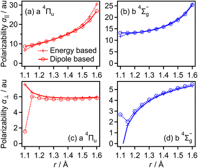
Transition dipole moments μt(r) as a function of r were obtained by GAMESS 2018 R159 at the MCSCF/aug-cc-pVTZ level followed by GUGA60 along with field-free potential energy curves. Fig. 18(a) and (b) show the resultant transition dipole moments of the f 4Πg–a 4Πu and c 4Σ−u–b 4Σ−g transitions, respectively.We also obtained the polarizabilities α‖ and α⊥ of O2+ in the a 4Πu and b 4Σ−g states as a function of r by the finite-element method as shown in Fig. 19(a)–(d). We found that α‖ linearly increases as r increases and α⊥ almost has a constant value in the range of r = 1.2–1.5 Å. We also confirm that the polarizabilities estimated by the energy based method and those estimated by the dipole based method are in agreement with each other in this r range. However, beyond this r range, the agreement of the polarizability between the two methods becomes worse. Therefore, we use linear fit α‖ in the range of r and the constant α⊥ value in the entire range of r in this CTMC simulation. For the f 4Πg and c 4Σ−u states, the agreements between the polarizabilities estimated by the two methods are worse than those for the a 4Πu and b 4Σ−g states even in the range of r = 1.2–1.5 Å. Considering that the f 4Πg and c 4Σ−u states are populated in the larger r range where it is hard to calculate the polarizabilities, we used the polarizabilities of O2+ in the a 4Πu and b 4Σ−g states instead of those in the f 4Πg and c 4Σ−u states, respectively.
Acknowledgements
This work was supported by JSPS KAKENHI Grant Numbers JP17K05593, JP21K18143, JP23H01918, JP23K13705 and JP23K26611 and by the Precise Measurement Technology Promotion Foundation (PMTP-F).Notes and references
- K. Codling and L. J. Frasinski, J. Phys. B: At., Mol. Opt. Phys., 1993, 26, 783–809 CrossRef.
- J. H. Posthumus, Rep. Prog. Phys., 2004, 67, 623–665 CrossRef.
- A. Giusti-Suzor, X. He, O. Atabek and F. H. Mies, Phys. Rev. Lett., 1990, 64, 515–518 CrossRef PubMed.
- P. H. Bucksbaum, A. Zavriyev, H. G. Muller and D. W. Schumacher, Phys. Rev. Lett., 1990, 64, 1883–1886 CrossRef PubMed.
- A. Zavriyev, P. H. Bucksbaum, H. G. Muller and D. W. Schumacher, Phys. Rev. A: At., Mol., Opt. Phys., 1990, 42, 5500–5513 CrossRef PubMed.
- A. Zavriyev, P. H. Bucksbaum, J. Squier and F. Saline, Phys. Rev. Lett., 1993, 70, 1077–1080 CrossRef PubMed.
- E. E. Aubanel, A. Conjusteau and A. D. Bandrauk, Phys. Rev. A: At., Mol., Opt. Phys., 1993, 48, R4011–R4014 CrossRef CAS PubMed.
- A. Giusti-Suzor, F. H. Mies, L. F. DiMauro, E. Charron and B. Yang, J. Phys. B: At., Mol. Opt. Phys., 1995, 28, 309–339 CrossRef CAS.
- R. Numico, A. Keller and O. Atabek, Phys. Rev. A: At., Mol., Opt. Phys., 1999, 60, 406–413 CrossRef CAS.
- L. J. Frasinski, C. R. Courtney and K. Codling, J. Mod. Opt., 2003, 50, 485–495 CrossRef CAS.
- M. Uhlmann, T. Kunert and R. Schmidt, Phys. Rev. A: At., Mol., Opt. Phys., 2005, 72, 045402 CrossRef.
- I. Heide, L. Catherine, D. B. André, S. André and L. François, J. Phys. B: At., Mol. Opt. Phys., 2018, 51, 042002 CrossRef.
- B. K. McFarland, J. P. Farrell, P. H. Bucksbaum and M. Guhr, Science, 2008, 322, 1232–1235 CrossRef PubMed.
- J. P. Farrell, B. K. McFarland, M. Gühr and P. H. Bucksbaum, Chem. Phys., 2009, 366, 15–21 CrossRef.
- Y. Mairesse, J. Higuet, N. Dudovich, D. Shafir, B. Fabre, E. Mével, E. Constant, S. Patchkovskii, Z. Walters, M. Y. Ivanov and O. Smirnova, Phys. Rev. Lett., 2010, 104, 213601 CrossRef PubMed.
- H. J. Wörner, J. B. Bertrand, P. Hockett, P. B. Corkum and D. M. Villeneuve, Phys. Rev. Lett., 2010, 104, 233904 CrossRef.
- C. Jin, J. B. Bertrand, R. R. Lucchese, H. J. Wörner, P. B. Corkum, D. M. Villeneuve, A.-T. Le and C. D. Lin, Phys. Rev. A: At., Mol., Opt. Phys., 2012, 85, 013405 CrossRef.
- O. Smirnova, Y. Mairesse, S. Patchkovskii, N. Dudovich, D. Villeneuve, P. B. Corkum and M. Y. Ivanov, Nature, 2009, 460, 972–977 CrossRef CAS PubMed.
- J. Yao, G. Li, X. Jia, X. Hao, B. Zeng, C. Jing, W. Chu, J. Ni, H. Zhang, H. Xie, C. Zhang, Z. Zhao, J. Chen, X. Liu, Y. Cheng and Z. Xu, Phys. Rev. Lett., 2013, 111, 133001 CrossRef PubMed.
- A. S. Alnaser, S. Voss, X. M. Tong, C. M. Maharjan, P. Ranitovic, B. Ulrich, T. Osipov, B. Shan, Z. Chang and C. L. Cocke, Phys. Rev. Lett., 2004, 93, 113003 CrossRef PubMed.
- T. Kanai, S. Minemoto and H. Sakai, Nature, 2005, 435, 470 CrossRef PubMed.
- D. Pavi
![[c with combining breve]](https://www.rsc.org/images/entities/char_0063_0306.gif) ić, K. F. Lee, D. M. Rayner, P. B. Corkum and D. M. Villeneuve, Phys. Rev. Lett., 2007, 98, 243001 CrossRef PubMed.
ić, K. F. Lee, D. M. Rayner, P. B. Corkum and D. M. Villeneuve, Phys. Rev. Lett., 2007, 98, 243001 CrossRef PubMed. - H. Akagi, T. Otobe, A. Staudte, A. Shiner, F. Turner, R. Dörner, D. M. Villeneuve and P. B. Corkum, Science, 2009, 325, 1364–1367 CrossRef PubMed.
- P. Simon, V. V. Yulian, S. Alejandro, C. Alberto and D. Piero, Phys. Rev. Lett., 2010, 104, 223001 CrossRef PubMed.
- J. L. Hansen, L. Holmegaard, J. H. Nielsen, H. Stapelfeldt, D. Dimitrovski and L. B. Madsen, J. Phys. B: At., Mol. Opt. Phys., 2012, 45, 015101 CrossRef.
- J. Wu, L. P. H. Schmidt, M. Kunitski, M. Meckel, S. Voss, H. Sann, H. Kim, T. Jahnke, A. Czasch and R. Dörner, Phys. Rev. Lett., 2012, 108, 183001 CrossRef CAS PubMed.
- X. Xie, K. Doblhoff-Dier, H. Xu, S. Roither, M. S. Schöffler, D. Kartashov, S. Erattupuzha, T. Rathje, G. G. Paulus, K. Yamanouchi, A. Baltuška, S. Gräfe and M. Kitzler, Phys. Rev. Lett., 2014, 112, 163003 CrossRef PubMed.
- H. Hasegawa, Y. Ikeda, K. Sonoda, T. Sato, A. Iwasaki and K. Yamanouchi, Chem. Phys. Lett., 2016, 662, 235–239 CrossRef CAS.
- P. Sándor, A. Sissay, F. Mauger, P. M. Abanador, T. T. Gorman, T. D. Scarborough, M. B. Gaarde, K. Lopata, K. J. Schafer and R. R. Jones, Phys. Rev. A, 2018, 98, 043425 CrossRef.
- H. V. S. Lam, S. Yarlagadda, A. Venkatachalam, T. N. Wangjam, R. K. Kushawaha, C. Cheng, P. Svihra, A. Nomerotski, T. Weinacht, D. Rolles and V. Kumarappan, Phys. Rev. A, 2020, 102, 043119 CrossRef CAS.
- T. N. Wangjam, H. V. S. Lam and V. Kumarappan, Phys. Rev. A, 2021, 104, 043112 CrossRef CAS.
- S. Fukahori, A. Iwasaki, K. Yamanouchi and H. Hasegawa, J. Chem. Phys., 2022, 156, 094307 CrossRef CAS PubMed.
- I. Kikuchi, S. Fukahori and H. Hasegawa, Phys. Rev. A, 2023, 108, 013101 CrossRef.
- S. Fukahori, I. Kikuchi and H. Hasegawa, Chem. Phys. Lett., 2023, 833, 140912 CrossRef.
- H. Stapelfeldt and T. Seideman, Rev. Mod. Phys., 2003, 75, 543–557 CrossRef.
- T. Seideman and E. Hamilton, Adv. At., Mol., Opt. Phys., 2005, 52, 289–329 Search PubMed.
- Y. Ohshima and H. Hasegawa, Int. Rev. Phys. Chem., 2010, 29, 619–663 Search PubMed.
- C. P. Koch, M. Lemeshko and D. Sugny, Rev. Mod. Phys., 2019, 91, 035005 CrossRef.
- H. Hu, Y. Hung, S. Larimian, S. Erattupuzha, A. Baltuška, M. Zeiler and X. Xie, Front. Phys., 2022, 10, 1076671 CrossRef.
- A. Hishikawa, S. Liu, A. Iwasaki and K. Yamanouchi, J. Chem. Phys., 2001, 114, 9856–9862 CrossRef CAS.
- S. De, M. Magrakvelidze, I. A. Bocharova, D. Ray, W. Cao, I. Znakovskaya, H. Li, Z. Wang, G. Laurent, U. Thumm, M. F. Kling, I. V. Litvinyuk, I. Ben-Itzhak and C. L. Cocke, Phys. Rev. A: At., Mol., Opt. Phys., 2011, 84, 043410 CrossRef.
- A. Sen, T. Sairam, S. R. Sahu, B. Bapat, R. Gopal and V. Sharma, J. Chem. Phys., 2020, 152, 014302 CrossRef CAS PubMed.
- H. Liu, S.-F. Zhao, M. Li, Y. Deng, C. Wu, X.-X. Zhou, Q. Gong and Y. Liu, Phys. Rev. A: At., Mol., Opt. Phys., 2013, 88, 061401 CrossRef.
- J. Yu, X. Yu, X. Zhao, Z. Yin, X. Li, P. Ma, C. Wang, S. Luo and D. Ding, J. Phys. B: At., Mol. Opt. Phys., 2020, 53, 085601 CrossRef CAS.
- O. Edqvist, E. Lindholm, L. E. Selin and L. Åsbrink, Phys. Scr., 1970, 1, 25 CrossRef CAS.
- A. M. Sayler, P. Q. Wang, K. D. Carnes, B. D. Esry and I. Ben-Itzhak, Phys. Rev. A: At., Mol., Opt. Phys., 2007, 75, 063420 CrossRef.
- M. Zohrabi, J. McKenna, B. Gaire, N. G. Johnson, K. D. Carnes, S. De, I. A. Bocharova, M. Magrakvelidze, D. Ray, I. V. Litvinyuk, C. L. Cocke and I. Ben-Itzhak, Phys. Rev. A: At., Mol., Opt. Phys., 2011, 83, 053405 CrossRef.
- X. M. Tong, Z. X. Zhao, A. S. Alnaser, S. Voss, C. L. Cocke and C. D. Lin, J. Phys. B: At., Mol. Opt. Phys., 2005, 38, 333–341 CrossRef CAS.
- A. Hishikawa, A. Iwamae, K. Hoshina, M. Kono and K. Yamanouchi, Chem. Phys., 1998, 231, 315–329 CrossRef CAS.
- E. Wigner, Phys. Rev., 1932, 40, 749–759 CrossRef CAS.
- X. M. Tong, Z. X. Zhao and C. D. Lin, Phys. Rev. A: At., Mol., Opt. Phys., 2002, 66, 033402 CrossRef.
- S.-F. Zhao, C. Jin, A.-T. Le, T. F. Jiang and C. D. Lin, Phys. Rev. A: At., Mol., Opt. Phys., 2010, 81, 033423 CrossRef.
- Y. Khodorkovsky, K. Kitano, H. Hasegawa, Y. Ohshima and I. S. Averbukh, Phys. Rev. A: At., Mol., Opt. Phys., 2011, 83, 023423 CrossRef.
- C. Ellert and P. B. Corkum, Phys. Rev. A: At., Mol., Opt. Phys., 1999, 59, R3170–R3173 CrossRef.
- I. Maruyama, T. Sako and K. Yamanouchi, J. Phys. B: At., Mol. Opt. Phys., 2004, 37, 3919–3936 CrossRef.
- J. C. Tully and R. K. Preston, J. Chem. Phys., 1971, 55, 562–572 CrossRef.
- J. W. C. Johns and D. W. Lepard, J. Mol. Spectrosc., 1975, 55, 374–406 CrossRef.
- K. Sonoda, S. Fukahori and H. Hasegawa, Phys. Rev. A, 2021, 103, 033118 CrossRef.
- G. M. J. Barca, C. Bertoni, L. Carrington, D. Datta, N. D. Silva, J. E. Deustua, D. G. Fedorov, J. R. Gour, A. O. Gunina, E. Guidez, T. Harville, S. Irle, J. Ivanic, K. Kowalski, S. S. Leang, H. Li, W. Li, J. J. Lutz, I. Magoulas, J. Mato, V. Mironov, H. Nakata, B. Q. Pham, P. Piecuch, D. Poole, S. R. Pruitt, A. P. Rendell, L. B. Roskop, K. Ruedenberg, T. Sattasathuchana, M. W. Schmidt, J. Shen, L. Slipchenko, M. Sosonkina, V. Sundriyal, A. Tiwari, J. L. G. Vallejo, B. Westheimer, M. Włoch, P. Xu, F. Zahariev and M. S. Gordon, J. Chem. Phys., 2020, 152, 154102 CrossRef CAS.
- M. Magrakvelidze, C. M. Aikens and U. Thumm, Phys. Rev. A: At., Mol., Opt. Phys., 2012, 86, 023402 CrossRef.
- T. Tanaka, H. Yoshii, Y. Morioka, T. Hayaishi, K. Ito and R. I. Hall, J. Chem. Phys., 1998, 108, 6240–6248 CrossRef.
- J. H. D. Eland and E. J. Duerr, Chem. Phys., 1998, 229, 1–11 CrossRef.
- M. Lundqvist, D. Edvardsson, P. Baltzer, M. Larsson and B. Wannberg, J. Phys. B: At., Mol. Opt. Phys., 1996, 29, 499 CrossRef.
- S. Hsieh and J. H. D. Eland, J. Phys. B: At., Mol. Opt. Phys., 1996, 29, 5795 CrossRef.
- S. Voss, A. S. Alnaser, X. M. Tong, C. Maharjan, P. Ranitovic, B. Ulrich, B. Shan, Z. Chang, C. D. Lin and C. L. Cocke, J. Phys. B: At., Mol. Opt. Phys., 2004, 37, 4239–4257 CrossRef.
- S. De, I. A. Bocharova, M. Magrakvelidze, D. Ray, W. Cao, B. Bergues, U. Thumm, M. F. Kling, I. V. Litvinyuk and C. L. Cocke, Phys. Rev. A: At., Mol., Opt. Phys., 2010, 82, 013408 CrossRef.
- W. Lai and C. Guo, Phys. Rev. A, 2016, 93, 043401 CrossRef.
| This journal is © the Owner Societies 2024 |

