Long-life sodium–sulfur batteries enabled by super-sodiophilic seeds†
Jiarui
He
 ,
Amruth
Bhargav
 and
Arumugam
Manthiram
 *
*
Materials Science and Engineering Program & Texas Materials Institute, The University of Texas at Austin, Austin, TX 78712, USA. E-mail: manth@austin.utexas.edu
First published on 9th September 2024
Abstract
Sodium–metal batteries (SMBs) are an appealing sustainable low-cost alternative to lithium–metal batteries due to their high theoretical capacity (1165 mA h g−1) and abundance of sodium. However, the practical viability of SMBs is challenged by a non-uniform deposition and uncontrollable growth of dendrites at the Na–metal anode. We employ here a super-sodiophilic BiF3 as a pre-planted seed to guide a uniform Na nucleation and deposition along the current collector. With the assistance of BiF3, Na metal infiltrates easily into a carbon nanotube (CNT) paper matrix within a second. Such a Na anode exhibits a superior cycle life of >2000 h with an extremely low overpotential of only 13.5 mV and a high coulombic efficiency of 99%. A full cell assembled with this anode and a sulfur cathode with a low negative to positive electrode capacity (N/P) ratio of ∼2 exhibits good cycling stability over 700 cycles. This work demonstrates a promising approach for the development of sustainable, low-cost SMBs.
Broader contextAdvanced energy-storage technologies are urgently needed to meet the growing demands for clean energy. It will be challenging to meet the projected future market demand with lithium-ion batteries (LIBs) due to their high cost. As a cost-effective alternative, sodium-based batteries are garnering significant attention due to the high abundance of sodium. Like sodium, sulphur is also abundant and inexpensive, and it offers an order of magnitude higher charge-storage capacity than the insertion-reaction cathodes currently employed in LIBs. However, room-temperature sodium–sulfur batteries generally suffer from low practical capacity and serious cycle life problems due to the severe sodium polysulfide shuttling and uncontrolled sodium dendritic growth. Herein, we report that commercial BiF3 particles serving as pre-planted seeds assist a uniform nucleation of sodium metal. BiF3 seeds facilitate an ultrafast loading of sodium metal into a CNT paper current collector within a second of immersion in molten sodium metal due to the super-sodiophilic property of BiF3. Based on these features, symmetric cells assembled with the obtained anode exhibit a superior cycle life of >2000 h with an extremely low overpotential of only 13.5 mV. This work provides a simple, scalable approach to Na-anode protection and is also instructive for other metal batteries. |
Introduction
The burgeoning demand for renewable energy storage and electric vehicles underscores the need for innovative battery technologies to sustain the growth.1–4 Lithium-ion batteries (LIBs), despite being the most prevalent energy storage technology, fall short of meeting the evolving demands of modern portable smart grids, electric vehicles, and electronic devices.5–9 As an alternative to LIBs for storing energy, sodium-based batteries offer great potential as next-generation energy storage systems due to the abundance and low cost of sodium-based minerals.10–12 Sodium metal with a low redox potential (−2.71 V vs. standard hydrogen electrode) and a high theoretical specific capacity (1166 mA h g−1) has garnered considerable research attention as an anode for sodium–metal batteries (SMBs) in recent years.13–16For decades, significant endeavors have been undertaken to elucidate the mechanisms underlying sodium (Na) deposition, mitigate dendrite formation, and stabilize the solid electrolyte interphase (SEI) in pursuit of unleashing the complete potential of sodium–metal anodes.17–20 Innovative approaches employed previously are use of solid-state electrolytes,21–24 optimization of liquid electrolytes,25–28 engineering of sodiophilic hosts/current collectors,29–32 and constructing interfacial protective layers.33–36 Of the various strategies, the engineering of sodiophilic hosts/current collectors is among the most promising, which can guide a uniform Na nucleation, enabling SEI stabilization, dendrite suppression, and volume change accommodation.37–39 However, the preparation procedures of many reported hosts are complicated, posing a challenge to practical viability.
Herein, we report commercial BiF3 particles serving as pre-planted seeds to guide a uniform Na nucleation and deposition in a matrix. The pulverization of BiF3 particles, often regarded as a significant drawback when employed as a cathode material, is envisioned in this study as a notable advantage. This behavior facilitates the rearrangement of nucleating seeds, consequently simplifying the process of introducing pre-planted seeds. In addition, BiF3 exhibits super-sodiophilic property, enabling an ultrafast loading of Na metal into carbon nanotube (CNT) paper current collector within a second of immersion in molten Na metal. Benefiting from these two distinctive features, symmetric cells assembled with the obtained anode exhibit a superior cycle life of >2000 h with an extremely low overpotential of only 13.5 mV. A pouch cell paired with a sulfur cathode and the obtained sodiophilic anode with a low negative to positive electrode capacity (N/P) ratio of ∼2 exhibits stable cycling performance over 50 cycles with a capacity of 661 mA h g−1.
Results and discussion
Synthesis route and mechanism
The synthetic route for the Na@CNT–BiF3 self-supporting electrodes is schematically shown in Fig. 1. It can be easily prepared by simply mixing CNT and BiF3via ultrasonication, followed by filtering, drying, and diffusing molten Na. It is worth noting that the CNT–BiF3 electrode is super-sodiophilic and can quickly adsorb molten Na metal into the material. As shown in Fig. S1 (ESI†), since commercialization is based on Cu foil current collectors rather than simple self-supporting electrodes, we have also achieved excellent electrochemical performance by coating commercial BiF3 paste onto a Cu foil. In addition, the BiF3 particles in the Na@CNT–BiF3 and Na@Cu–BiF3 electrodes gradually pulverize and uniformly cover CNT after alloying/dealloying of BiF3 with increasing number of cycles,40,41 effectively improving the uniformity and electrochemical properties of the Na@CNT–BiF3 and Na@Cu–BiF3 electrodes materials. | ||
| Fig. 1 Synthetic route and mechanism. Illustration of the synthetic route and mechanism after the cycling of Na@CNT–BiF3. | ||
Electrochemical performance of sodium–metal anode
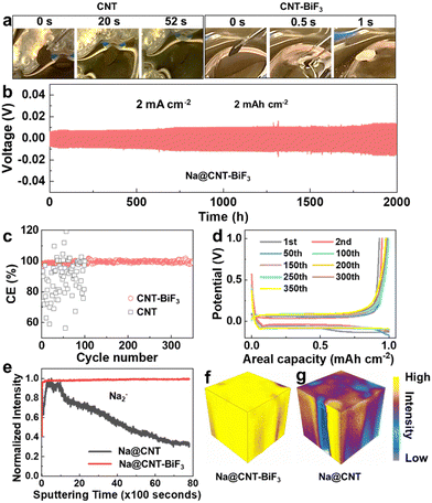
To further assess the sodiophilicity of CNT@-BiF3 and CNT electrodes for molten Na, the time required for the electrodes to fully adsorb molten Na metal was compared macroscopically (Fig. 2a and Videos S1 and S2, ESI†). Notably, the CNT@BiF3 electrode fully adsorbed molten Na metal within a second, whereas the CNT electrode took 52 s only to adsorb a small amount of molten Na, demonstrating the high sodiophilicity of BiF3 particles in greatly improving the sodiophilicity of CNT@BiF3. The cycling stability of the Na@CNT–BiF3 anode was further assessed with symmetric cells at a current density of 2 mA cm−2 and an areal capacity of 2 mA h cm−2. As seen in Fig. 2b and Fig. S2 (ESI†), the symmetric cell with Na@CNT–BiF3 displays an overpotential of only 6 mV initially, followed by a slight increase of up to 13.5 mV, but shows a remarkable lifespan of over 2000![[thin space (1/6-em)]](https://www.rsc.org/images/entities/char_2009.gif) h. The coulombic efficiency (CE) is a very vital parameter to reflect the side reactions between electrodes and electrolytes. The CE of the cell with the Cu‖Na@CNT electrode exhibits strong irregular fluctuations (Fig. 2c), which may be due to the CNT surface having poor sodiophilicity. The lack of an effective nucleation surface leads to a loss of active Na during plating/stripping, accompanied by a reconstruction and cracking of the SEI. As a comparison, the Cu‖Na@CNT–BiF3 cell presents a well-maintained CE of 99% after 350 cycles, demonstrating a great improvement in Na plating/stripping reversibility. Additionally, the corresponding discharge–charge curves of the Cu‖Na@CNT–BiF3 cell show a low Na nucleation overpotential with constant, overlapping plateaus during repetitive cycling (Fig. 2d).
h. The coulombic efficiency (CE) is a very vital parameter to reflect the side reactions between electrodes and electrolytes. The CE of the cell with the Cu‖Na@CNT electrode exhibits strong irregular fluctuations (Fig. 2c), which may be due to the CNT surface having poor sodiophilicity. The lack of an effective nucleation surface leads to a loss of active Na during plating/stripping, accompanied by a reconstruction and cracking of the SEI. As a comparison, the Cu‖Na@CNT–BiF3 cell presents a well-maintained CE of 99% after 350 cycles, demonstrating a great improvement in Na plating/stripping reversibility. Additionally, the corresponding discharge–charge curves of the Cu‖Na@CNT–BiF3 cell show a low Na nucleation overpotential with constant, overlapping plateaus during repetitive cycling (Fig. 2d).
To further investigate the interphase composition formed on the surface of the Na@CNT and Na@CNT–BiF3, time-of-flight-secondary ion mass spectrometric (TOF-SIMS) depth profiling was employed, which is an advanced technique to identify the chemical composition of the solid surface within its depth.42,43 As shown in Fig. 2e, the depth profiles reveal the uniformity of Na infiltration into the matrix in Na@CNT and Na@CNT–BiF3 anode via the Na2− secondary-ion as a representative species. The Na2− intensity in Na@CNT anode shows two peaks consecutively and then decreases continuously, which indicates that the poor sodiophilicity of Na@CNT results in a non-uniform incorporation of metallic Na. The 3D reconstruction of the elemental depth profiles of Na@CNT in Fig. 2g further reaffirms the inhomogeneous Na metal distribution. It is reasonable to posit that the non-uniformity leads to dendrite formation and irregular cycling, as observed in Fig. 2c. On the other hand, the continuous signal for Na2− intensity in Na@CNT–BiF3 indicates a uniform infiltration of Na metal, despite the presence of large BiF3 particles in the CNT. In further support, the 3D reconstruction of the Na@CNT–BiF3 electrode in Fig. 2f shows a homogeneous Na2− signal over the whole investigated depth. The continual abundance of seeding sites leads to a consistent performance of the cell, observed in Fig. 2c and d.
Sodium storage mechanism and the behavior of sodium–metal anode
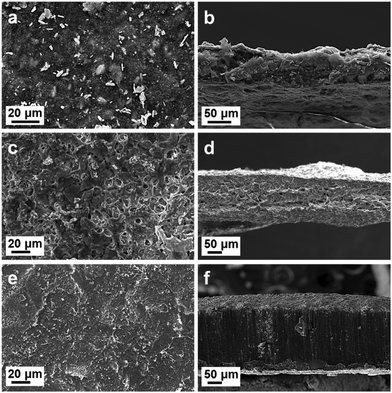
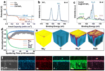
In addition, to observe the morphological changes of Na metal at the CNT–BiF3 electrode microscopically, the top-surface and cross-sectional SEM images of CNT–BiF3, Na@CNT–BiF3 (before cycling), and Na@CNT–BiF3 (after 200 cycles) electrodes are compared in Fig. 3. Fig. 3(a and b) shows uniformly distributed, large (micron-sized) BiF3 particles in the CNT–BiF3 electrode. The top-surface and cross-sectional morphologies of the CNT–BiF3 electrode after adsorbing molten Na are shown in Fig. 3(c and d) shows the top-surface and cross-sectional morphologies of the CNT–BiF3 electrode after adsorbing molten Na (before cycling). As seen, there are no obvious BiF3 particles on the top surface, due to the rapid pulverization and quick coverage by Na metal during the adsorption of molten Na. In addition, from the cross-sectional SEM image, it can be seen that there are still many pores and gap structures after the adsorption of Na metal, which can effectively buffer the volume expansion during the cycling process. To this end, the structural changes of the Na@CNT–BiF3 electrode after 200 cycles can be observed in Fig. 3(e and f). The SEM images show that the size of the surface BiF3 particles is smaller and more uniformly distributed. In addition, the pores in the cross-sectional SEM are filled and thus become denser, which may be attributed to the continuous alloying/de-alloying of BiF3 during the cycling process. The repeated alloying process causes BiF3 to break down into small particles that get homogenously distributed such that they occupy more volume compared to the initial stage. Thus, the void spaces that existed in Na@CNT–BiF3 electrode before cycling are filled during the Na plating process.To better understand the Na storage mechanism, Na plating behavior on Cu, CNT, and CNT–BiF3 substrates was studied. The potential–capacity curves in Fig. 4a show a deep dip in the potential caused by the Na–metal nucleation barrier. This nucleation potential for Cu, CNT, and CNT–BiF3 are, respectively, 428, 383, and 129 mV. The low overpotential for CNT–BiF3 indicates that it is a highly favorable substrate to plate Na–metal with a fast Na+ diffusion rate. It also means that BiF3 is labile for conversion by easily reacting with Na. The conversion was confirmed by comparing the X-ray photoelectron spectroscopy (XPS) data of CNT–BiF3 (Fig. 4b) and Na@CNT–BiF3 (Fig. 4c). As expected, the spectrum of CNT–BiF3 shows the Bi 4f7/2 peak at 160.8 eV. On plating Na on the CNT–BiF3 electrode, a new Bi 4f7/2 peak at 155.8 eV corresponding to metallic Bi is observed. This peak appears at a lower binding energy than expected for metallic Bi (156.9 eV), potentially due to the formation of Na–Bi alloy, indicating that the Na is not just physically plated, but rather chemically reacting with and converting BiF3. Furthermore, the peak for BiF3 persists even after sodium plating, implying that BiF3 progressively undergoes pulverization followed by conversion to metallic Bi with cycling. This steady conversion process ensures continuous availability of BiF3, which acts as seeds and thus ensures uniform plating.
To better understand the surface and bulk characteristics of the Na@CNT–BiF3 anode cycled in a localized high-concentration electrolyte (LHCE), ToF-SIMS on the cycled anode was performed. The LHCE consists of sodium bis(fluorosulfonyl) imide (NaFSI)![[thin space (1/6-em)]](https://www.rsc.org/images/entities/char_2009.gif) :
:![[thin space (1/6-em)]](https://www.rsc.org/images/entities/char_2009.gif) 1,2-dimethoxyethane (DME)
1,2-dimethoxyethane (DME)![[thin space (1/6-em)]](https://www.rsc.org/images/entities/char_2009.gif) :
:![[thin space (1/6-em)]](https://www.rsc.org/images/entities/char_2009.gif) 1,1,2,2-tetrafluoroethyl 2,2,3,3-tetrafluoropropyl ether (TTE) in 1
1,1,2,2-tetrafluoroethyl 2,2,3,3-tetrafluoropropyl ether (TTE) in 1![[thin space (1/6-em)]](https://www.rsc.org/images/entities/char_2009.gif) :
:![[thin space (1/6-em)]](https://www.rsc.org/images/entities/char_2009.gif) 1.2
1.2![[thin space (1/6-em)]](https://www.rsc.org/images/entities/char_2009.gif) :
:![[thin space (1/6-em)]](https://www.rsc.org/images/entities/char_2009.gif) 1 (molar ratio). Fig. 4d shows the depth profiles and Fig. 4e shows the 3D reconstruction of the secondary-ion species, such as Na2−, C−, Na2F−, and NaS−, which are representative of, respectively, metallic Na, CNT, BiF3, and LHCE electrolyte. It can be seen from the depth profiles and 3D model that the signals for Na2− and C− gradually increase to reach a uniform and stable level by the end of sputtering, which is similar to the trend of secondary ion Na2− signal in the original Na@CNT–BiF3 anode (Fig. 2f), suggesting that the structure of CNT matrix and the homogenous Na distribution are maintained across cycling. In addition, the SEI layer was analyzed by the secondary ions Na2F− and NaS−. First, the signal of Na2F− gradually decreases until about 2000 s of sputtering time and then it stabilizes, indicating that a compact NaF–rich SEI is formed, as seen in the 3D reconstruction. This layer suppresses the growth of dendrites, while providing fast ion transport, which is responsible for the high CE observed. The NaS− signal from the electrolyte follows a trend similar to that of Na2F− in the SEI layer, which indicates that the inorganic–rich NaF and Na2S layers protect the underlying Na–metal from continuous electrolyte exposure and decomposition. Fig. 4f displays the cross-sectional SEM micrograph along with the elemental mapping distributions of C, Bi, F, Na, and S elements across a cycled Na@CNT–BiF3 anode. The carbon signal is uniformly distributed in the whole cross-section, which confirms that the structure of the electrode remains intact and stable. The concentration of F and S near the surface aligns with the ToF-SIMS data, reaffirming the NaF and Na2S layers shield the Na–metal from electrolyte degradation.
1 (molar ratio). Fig. 4d shows the depth profiles and Fig. 4e shows the 3D reconstruction of the secondary-ion species, such as Na2−, C−, Na2F−, and NaS−, which are representative of, respectively, metallic Na, CNT, BiF3, and LHCE electrolyte. It can be seen from the depth profiles and 3D model that the signals for Na2− and C− gradually increase to reach a uniform and stable level by the end of sputtering, which is similar to the trend of secondary ion Na2− signal in the original Na@CNT–BiF3 anode (Fig. 2f), suggesting that the structure of CNT matrix and the homogenous Na distribution are maintained across cycling. In addition, the SEI layer was analyzed by the secondary ions Na2F− and NaS−. First, the signal of Na2F− gradually decreases until about 2000 s of sputtering time and then it stabilizes, indicating that a compact NaF–rich SEI is formed, as seen in the 3D reconstruction. This layer suppresses the growth of dendrites, while providing fast ion transport, which is responsible for the high CE observed. The NaS− signal from the electrolyte follows a trend similar to that of Na2F− in the SEI layer, which indicates that the inorganic–rich NaF and Na2S layers protect the underlying Na–metal from continuous electrolyte exposure and decomposition. Fig. 4f displays the cross-sectional SEM micrograph along with the elemental mapping distributions of C, Bi, F, Na, and S elements across a cycled Na@CNT–BiF3 anode. The carbon signal is uniformly distributed in the whole cross-section, which confirms that the structure of the electrode remains intact and stable. The concentration of F and S near the surface aligns with the ToF-SIMS data, reaffirming the NaF and Na2S layers shield the Na–metal from electrolyte degradation.
The above studies show that the Na@CNT–BiF3 forms and maintains a stable interface through cycling.
To better understand the mechanism by which Na–metal can easily diffuse into a matrix of BiF3 and to understand the chemical difference in the Na stripping/plating behavior between the CNT and CNT–BiF3 anodes, synchrotron-based in operando X-ray diffraction (XRD) experiments were performed (the test mechanism schematic is shown in Fig. S3, ESI†). Fig. 5 presents the in operando XRD results of Na‖CNT and Na‖CNT–BiF3 cells cycled with the LHCE in custom coin cells with a window, as described in our previous work.44 The cells were tested at 1 mA cm−2 for one full plating/stripping process, during which the XRD pattern was simultaneously recorded to probe the Na plating/stripping with a small volume where the X-rays are focused as presented by the contour plot next to the voltage profile.
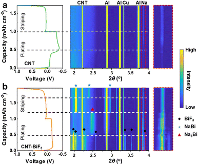 | ||
| Fig. 5 In operando X-ray diffraction (XRD) characterization. Charge and discharge curves of (a) Na@CNT‖Na@CNT and (b) Na@CNT–BiF3‖Na@CNT–BiF3 coin cell and the corresponding diffraction patterns. | ||
In the contour plot of the cell with Na@CNT anode (Fig. 5a), peaks corresponding to Na metal plating on the CNT matrix can be detected when about 0.5 mA h cm−2 is plated, and the peak intensity grows stronger with continuous plating. While stripping, the intensity reduces, but a faint intensity is still detected at the end of the stripping process, which can act as the nucleation site during the subsequent plating steps. In addition, the intensity of the characteristic Na peaks after complete desodiation is significantly stronger than that before initial plating, indicating significant irreversibility of Na plating/striping, which may be responsible for the growth of dendrites. In contrast, as shown in Fig. 5b, during the sodium plating process of CNT–BiF3 anode, strong Na metal, and BiF3 characteristic peaks are present at the beginning of the plating step. The intensity of the Na–metal peak is much stronger in the case of CNT–BiF3 compared to pure CNT, indicating that the probed volume quickly fills with Na metal, owing to BiF3 acting as a strong seeding layer, while the sparse Na distribution in the case of CNT is reflected in a weaker signal. This also points to the good sodiophilicity of the matrix with BiF3. By the time 0.5 mA h cm−2 is plated, the signal for Na3Bi can be observed, while the Na metal signal intensifies. This indicates that the conversion-alloying process drives the dense plating of Na in the matrix. The formation of Na3Bi and NaBi, as indicated by the in-situ XRD along with the presence of NaF signal in the ToF-SIMS and SEM data in Fig. 4, suggests that the facile conversion of BiF3 into Na–Bi alloys and NaF is the reason for the high sodiophilicity of a BiF3 containing matrix, which allows for the ultra-quick melt-infusion of Na metal. In addition, the intensity of the characteristic Na peak after complete sodium removal is significantly weaker than that before initial plating, suggesting that Na plating/stripping is reversible.
During the stripping process, the characteristic peak of Na3Bi is gradually transformed into NaBi, and the characteristic peak of Na metal is obviously and gradually weakened. The remaining Na metal and the NaBi alloy act as an excelling seeding layer in the subsequent plating step, thus guiding a dendrite-free nucleation and growth of Na.45,46 In essence, the addition of BiF3 improves the sodiophilicity of CNT, resulting in a highly reversible Na plating/striping and alloying/de-alloying process for Na@CNT–BiF3 anode. Overall, from the above XRD data, in a melt-infiltrated Na@CNT–BiF3 anode, the following (electro)chemical process can be envisioned:
Plating process:
| Na+ + e− → Na |
| Bi3+ + 6e− + 3Na+ → Na3Bi |
Stripping process:
| Na3Bi → NaBi + 2e− + 2Na+ |
| Na → Na+ + e− |
Electrochemical performance of Na@CNT–BiF3 and Na@Cu–BiF3
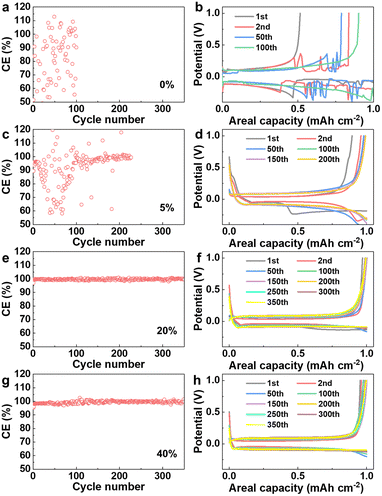
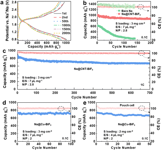
Generally, self-supporting electrodes can provide higher energy density, but practical applications necessitate the use of Cu foil as the current collector. Hence, for further practical and scalable application, the electrochemical performance of BiF3 coated onto Cu collector was tested. Here, different contents of BiF3 electrodes were assembled into Na‖Cu cells to characterize the CE and corresponding voltage profile curves for sodium plating/stripping. Fig. 6(a and b) shows the CE and the corresponding voltage profiles for the blank control group of Cu anode with 0% BiF3. It is observed that the CE is very unstable and the voltage profiles fluctuate with high sodium–metal nucleation potentials and low capacity. These fluctuations may be due to the dendrite growth leading to a short circuit of the cell. Fig. 6(c–h) compares the CE with the corresponding voltage profiles for the Cu anodes with 5% BiF3, 20% BiF3, and 40% BiF3. The CE is increased when 5% BiF3 is added, and its voltage profiles are relatively smooth with the CE being stabilized only after cycling up to 100 cycles. However, the CE becomes much more stable when BiF3 is added up to 20% and the corresponding voltage profiles are stable with a low Na metal nucleation overpotential. When BiF3 is increased to 40%, the cells cycle with relatively good stability. However, the CE fluctuations are slightly increased compared to that with 20%BiF3. The increased content of BiF3 and its longer alloying transformation affect the CE. Therefore, in consideration of cost and economics, 20% BiF3 addition improves both the sodiophilicity of the electrode and keeps the Na loss at less than 5% in the first cycle.To demonstrate the practical application of the conversion composite anode, high-energy C/S cathode was matched with bare Na and Na@CNT–BiF3 anodes to make Na–S cells. In these cells, the sulfur loading is 3 mg cm−2, and the electrolyte-to-sulfur (E/S) ratio is controlled to be 7 μL mg−1 with an ultra-low N/P ratio of 2.8 to showcase the stability of the anode. Fig. 7a displays the voltage profiles of Na@CNT–BiF3‖C/S cell at different cycles at 0.1C rate (1C = 1675 mA g−1) within the voltage range of 0.8–2.8 V. It is noteworthy that there is no obvious irreversible capacity loss region with Na polysulfide (NaPSs) transformation in the voltage profiles of the initial cycles. The stability of the charge/discharge curves implies that the Na@CNT–BiF3 anode surface is resistant to the shuttle of polysulfides.
The Na@CNT–BiF3‖C/S cell presents an initial discharge and charge capacities of, respectively, 1010 and 972 mA h g−1 with an initial coulombic efficiency (ICE) of 104%, as shown in Fig. 7b. This is attributed to the introduction of super-sodiophilic BiF3 particles and the rapid self-adsorption of sodium by Na@CNT–BiF3, improving the kinetic properties of Na+. Even through 200 cycles, the capacity remains at 862 mA h g−1, corresponding to a capacity retention of 85%. The CE at the 200th cycle is nearly 100%, which demonstrates minimal polysulfide shuttling occurs during cycling. On the other hand, the cell with bare Na anode shows poor cycling performance with a rapid capacity fade within 75 cycles and finally displays a very low capacity of only 165 mA h g−1 after 150 cycles. Furthermore, the CE fluctuates during cycling, suggesting irreversible reactions between the electrolyte and the bare Na–metal anode lead to capacity loss. In essence, the Na@CNT–BiF3 anode demonstrates significant potential for high-performance Na–S batteries with impressive capacity, minimal capacity decay, and prolonged cycling lifespan, outperforming numerous Na–S batteries (Table S1, ESI†). The Na@CNT–BiF3‖C/S cell was further tested at a higher current density of 1C rate to reveal the kinetics of the reaction and the structural stability of the anode. Fig. 7c shows that the Na@CNT–BiF3‖C/S cell can still provide a discharge capacity of 674 mA h g−1 even after 700 cycles, corresponding to a capacity retention of 77%, indicating a highly reversible reaction in the cell.
As mentioned before, Na@Cu–BiF3 is a practical alternative to the freestanding Na@CNT–BiF3 as it has a metallic current collector, allowing for the processing of large electrodes. To validate this, the cycling performance of the Na@Cu–BiF3‖C/S cell was tested with a sulfur loading of 3 mg cm−2, a low E/S of 7 μL mg−1, a low N/P ratio of 2, and at a current of 0.1C, as shown in Fig. 7d and Fig. S4 (ESI†). The Na@Cu–BiF3 anode exhibits an initial capacity of 735 mA g−1 and excellent cycling stability, with a capacity retention of close to 100% after 100 cycles. The presence of a Cu current collector affords the construction of Na–S pouch cells as tabs can be easily welded. Therefore, Na@Cu–BiF3‖C/S pouch cells were assembled to validate our concept, featuring a 2 mg cm−2 loading, a low E/S of 4 μL mg−1, and a low N/P ratio of 2. As depicted in Fig. 7e, the pouch cell presents a capacity of 661 mA h g−1 at 0.1C rate after 50 cycles, indicating the effective utilization of sulfur operating with low E/S and limited N/P ratios. This further validates that BiF3 super-sodiophilic seeds can accelerate sodium plating/striping, improving the NaPSs kinetic performance and reducing the shuttle effect of NaPSs. These results highlight the promise of integrating Na@Cu–BiF3 in the development of high-performance, practically feasible Na–S batteries.
Conclusions
In summary, BiF3 is demonstrated to be a super-sodiophilic seed for Na–metal anodes in sodium–metal batteries. When BiF3 is integrated into a matrix of CNT, molten Na metal can be incorporated into the substrate in a facile and rapid manner owing to the conversion-alloying reaction of BiF3. The Na@CNT–BiF3 anode thus forms a NaF− and Na2S-rich interphase with the electrolyte when cycled in an LHCE. This interphase is compact, yet robust, to prevent continuous electrolyte degradation at the anode, which enables long-term cycling. The constant pulverization and conversion of BiF3 through cycling provides an efficient seed layer that suppresses dendrite formation. In addition to the free-standing format, BiF3 can be coated onto a metallic current collector, such as Cu foil, and mixed with molten Na metal to yield an anode. The Na@Cu–BiF3 anodes could be easily incorporated into prototype pouch cells, which showed excellent cycling stability in Na–S batteries, especially while operating at a low N/P ratio of 2. This work provides a simple, scalable approach forward to Na-anode protection and is also instructive for other metal batteries with different working conditions.Author contributions
J. H., A. B., and A. M. conceived the idea. J. H. performed cathode formulations and collected the electrochemical data. A. B performed the pouch cell experiments. A. M. supervised the project. All authors were involved in discussing the results and writing and reviewing the manuscript.Data availability
The datasets generated during and/or analyzed during the current study are available from the corresponding author upon request.Conflicts of interest
There are no conflicts to declare.Acknowledgements
This work was supported by the U.S. Department of Energy, Office of Basic Energy Sciences, Division of Materials Science and Engineering under award number DE-SC0005397. The authors thank Drs Harry Charalambous and Laisuo Su for their assistance with the collection of synchrotron X-ray diffraction data.Notes and references
- Y. Liu, X. Tao, Y. Wang, C. Jiang, C. Ma, O. Sheng, G. Lu and X. W. Lou, Science, 2022, 375, 739–745 CrossRef PubMed
.
- X. Liu, J. Zhu, X. Wang, L. Yue, W. Wang, B. Wang, D. Shen and Y. Li, Adv. Funct. Mater., 2023, 33, 2209388 CrossRef
.
- X. Liu, J. Zhu, L. Yue, X. Wang, W. Wang, T. Zheng and Y. Li, Small, 2022, 18, 2204552 CrossRef
.
- Q. Pang, J. Meng, S. Gupta, X. Hong, C. Y. Kwok, J. Zhao, Y. Jin, L. Xu, O. Karahan and Z. Wang, Nature, 2022, 608, 704–711 CrossRef CAS PubMed
.
- L. Jiang, Y. Lu, C. Zhao, L. Liu, J. Zhang, Q. Zhang, X. Shen, J. Zhao, X. Yu and H. Li, Nat. Energy, 2019, 4, 495–503 CrossRef CAS
.
- Y. Zou, Z. Ma, G. Liu, Q. Li, D. Yin, X. Shi, Z. Cao, Z. Tian, H. Kim and Y. Guo, Angew. Chem., Int. Ed., 2023, 135, e202216189 CrossRef
.
- X. Liu, X. Wang, Y. Zhou, B. Wang, L. Zhao, H. Zheng, J. Wang, J. Liu, J. Liu and Y. Li, Adv. Mater., 2024, 36, 2308447 CrossRef CAS PubMed
.
- S. Zhang, Q. Fan, Y. Liu, S. Xi, X. Liu, Z. Wu, J. Hao, W. K. Pang, T. Zhou and Z. Guo, Adv. Mater., 2020, 32, 2000380 CrossRef CAS PubMed
.
- J. Meng, X. Hong, Z. Xiao, L. Xu, L. Zhu, Y. Jia, F. Liu, L. Mai and Q. Pang, Nat. Commun., 2024, 15, 596 CrossRef CAS
.
- T. Deng, X. Ji, L. Zou, O. Chiekezi, L. Cao, X. Fan, T. R. Adebisi, H.-J. Chang, H. Wang and B. Li, Nat. Nanotechnol., 2022, 17, 269–277 CrossRef CAS PubMed
.
- C. Xu, Y. Ma, J. Zhao, P. Zhang, Z. Chen, C. Yang, H. Liu and Y. S. Hu, Angew. Chem., Int. Ed., 2023, 62, e202217761 CrossRef CAS
.
- T. Liu, Y. Yang, S. Cao, R. Xiang, L. Zhang and J. Yu, Adv. Mater., 2023, 35, 2207752 CrossRef CAS PubMed
.
- X. Xia, S. Xu, F. Tang, Y. Yao, L. Wang, L. Liu, S. He, Y. Yang, W. Sun and C. Xu, Adv. Mater., 2023, 35, 2209511 CrossRef CAS
.
- H. Liu, X. Zheng, Y. Du, M. C. Borrás, K. Wu, K. Konstantinov, W. K. Pang, S. Chou, H. Liu and S. Dou, Adv. Mater., 2024, 36, 2307645 CrossRef CAS
.
- R. Zhuang, X. Zhang, C. Qu, X. Xu, J. Yang, Q. Ye, Z. Liu, S. Kaskel, F. Xu and H. Wang, Sci. Adv., 2023, 9, eadh8060 CrossRef CAS
.
- J. He, A. Bhargav, L. Su, J. Lamb, J. Okasinski, W. Shin and A. Manthiram, Nat. Energy, 2024, 1–11 Search PubMed
.
- B. Sayahpour, W. Li, S. Bai, B. Lu, B. Han, Y.-T. Chen, G. Deysher, S. Parab, P. Ridley and G. Raghavendran, Energy Environ. Sci., 2024, 17, 1216–1228 RSC
.
- G. Sun, C. Lou, B. Yi, W. Jia, Z. Wei, S. Yao, Z. Lu, G. Chen, Z. Shen and M. Tang, Nat. Commun., 2023, 14, 6501 CrossRef CAS
.
- S. Wang, S. Weng, X. Li, Y. Liu, X. Huang, Y. Jie, Y. Pan, H. Zhou, S. Jiao and Q. Li, Angew. Chem., Int. Ed., 2023, 135, e202313447 CrossRef
.
- S. Zhang, Y. Liu, Q. Fan, C. Zhang, T. Zhou, K. Kalantar-Zadeh and Z. Guo, Energy Environ. Sci., 2021, 14, 4177–4202 RSC
.
- P. Wen, P. Lu, X. Shi, Y. Yao, H. Shi, H. Liu, Y. Yu and Z. S. Wu, Adv. Energy Mater., 2021, 11, 2002930 CrossRef CAS
.
- J. A. S. Oh, G. Deysher, P. Ridley, Y. T. Chen, D. Cheng, A. Cronk, S. Y. Ham, D. H. Tan, J. Jang and L. H. B. Nguyen, Adv. Energy Mater., 2023, 2300776 CrossRef CAS
.
- X. Wang, C. Zhang, M. Sawczyk, J. Sun, Q. Yuan, F. Chen, T. C. Mendes, P. C. Howlett, C. Fu and Y. Wang, Nat. Mater., 2022, 21, 1057–1065 CrossRef CAS
.
- M. He, L. Zhu, G. Ye, Y. An, X. Hong, Y. Ma, Z. Xiao, Y. Jia and Q. Pang, Angew. Chem., Int. Ed., 2024, 136, e202401051 CrossRef
.
- Q. Chen, W. Zhuang, Z. Hou, Y. Jiang, J. Wan, T. Zhang, Y. Zhao and L. Huang, Adv. Funct. Mater., 2023, 33, 2210206 CrossRef CAS
.
- H. Wang, C. Zhu, J. Liu, S. Qi, M. Wu, J. Huang, D. Wu and J. Ma, Angew. Chem., Int. Ed., 2022, 134, e202208506 CrossRef
.
- X. Zhou, Q. Zhang, Z. Zhu, Y. Cai, H. Li and F. Li, Angew. Chem., Int. Ed., 2022, 134, e202205045 CrossRef
.
- K. Doi, Y. Yamada, M. Okoshi, J. Ono, C. P. Chou, H. Nakai and A. Yamada, Angew. Chem., Int. Ed., 2019, 131, 8108–8112 CrossRef
.
- X. Li, W. Ye, P. Xu, H. Huang, J. Fan, R. Yuan, M. S. Zheng, M. S. Wang and Q. Dong, Adv. Mater., 2022, 34, 2202898 CrossRef CAS
.
- P. Wang, G. Zhang, X.-Y. Wei, R. Liu, J.-J. Gu and F.-F. Cao, J. Am. Chem. Soc., 2021, 143, 3280–3283 CrossRef CAS PubMed
.
- K. Lee, Y. J. Lee, M. J. Lee, J. Han, J. Lim, K. Ryu, H. Yoon, B. H. Kim, B. J. Kim and S. W. Lee, Adv. Mater., 2022, 34, 2109767 CrossRef CAS
.
- F. Xu, C. Qu, Q. Lu, J. Meng, X. Zhang, X. Xu, Y. Qiu, B. Ding, J. Yang and F. Cao, Sci. Adv., 2022, 8, eabm7489 CrossRef CAS
.
- Y. Jiang, Y. Yang, F. Ling, G. Lu, F. Huang, X. Tao, S. Wu, X. Cheng, F. Liu and D. Li, Adv. Mater., 2022, 34, 2109439 CrossRef CAS
.
- L. Zhao, Z. Hu, Z. Huang, Y. Tao, W. H. Lai, A. Zhao, Q. Liu, J. Peng, Y. Lei and Y. X. Wang, Adv. Energy Mater., 2022, 12, 2200990 CrossRef CAS
.
- X. Zhou, F. Liu, Y. Wang, Y. Yao, Y. Shao, X. Rui, F. Wu and Y. Yu, Adv. Energy Mater., 2022, 12, 2202323 CrossRef CAS
.
- M. Zhu, G. Wang, X. Liu, B. Guo, G. Xu, Z. Huang, M. Wu, H. K. Liu, S. X. Dou and C. Wu, Angew. Chem., Int. Ed., 2020, 132, 6658–6662 CrossRef
.
- S. Li, H. Zhu, Y. Liu, Q. Wu, S. Cheng and J. Xie, Adv. Mater., 2023, 35, 2301967 CrossRef CAS PubMed
.
- L. Yue, Y. Qi, Y. Niu, S. Bao and M. Xu, Adv. Energy Mater., 2021, 11, 2102497 CrossRef CAS
.
- J. Wang, Y. Gao, D. Liu, G. Zou, L. Li, C. Fernandez, Q. Zhang and Q. Peng, Adv. Mater., 2024, 36, 2304942 CrossRef CAS
.
- Z. Yu, J. Song, M. L. Gordin, R. Yi, D. Tang and D. Wang, Adv. Sci., 2015, 2, 1400020 CrossRef
.
- W. Li, H. Li, Z. Lu, L. Gan, L. Ke, T. Zhai and H. Zhou, Energy Environ. Sci., 2015, 8, 3629–3636 RSC
.
- J. Kim, J. Kim, J. Jeong, J. Park, C.-Y. Park, S. Park, S. G. Lim, K. T. Lee, N.-S. Choi and H. R. Byon, Energy Environ. Sci., 2022, 15, 4109–4118 RSC
.
- Y.-J. Lei, X. Lu, H. Yoshikawa, D. Matsumura, Y. Fan, L. Zhao, J. Li, S. Wang, Q. Gu and H.-K. Liu, Nat. Commun., 2024, 15, 3325 CrossRef CAS PubMed
.
- Y. Xiao, F. Liu, H. Shi, L. Hou, G. Qin, C. Yuan and X. W. Lou, Adv. Mater., 2023, 2301772 CrossRef
.
- G. Liu, Z. Sun, X. Shi, X. Wang, L. Shao, Y. Liang, X. Lu, J. Liu and Z. Guo, Adv. Mater., 2023, 35, 2305551 CrossRef CAS PubMed
.
- X. Cheng, R. Shao, D. Li, H. Yang, Y. Wu, B. Wang, C. Sun, Y. Jiang, Q. Zhang and Y. Yu, Adv. Funct. Mater., 2021, 31, 2011264 CrossRef CAS
.
Footnote |
| † Electronic supplementary information (ESI) available. See DOI: https://doi.org/10.1039/d4ee02996h |
| This journal is © The Royal Society of Chemistry 2024 |

