Co-recovery of spent LiCoO2 and LiFePO4 by paired electrolysis†
Jingjing
Zhao
a,
Fengyin
Zhou
a,
Hongya
Wang
a,
Xin
Qu
a,
Danfeng
Wang
a,
Zhiyu
Zheng
a,
Yuqi
Cai
a,
Shuaibo
Gao
 *a,
Dihua
Wang
 ab and
Huayi
Yin
 *ab
*ab
aSchool of Resource and Environmental Science, Wuhan University, 299 Bayi Road, Wuchang District, Wuhan 430072, P. R. China. E-mail: 1281850276@qq.com; yinhuayi@whu.edu.cn
bHubei International Scientific and Technological Cooperation Base of Sustainable Resources and Energy, Wuhan 430072, P. R. China
First published on 29th November 2023
Abstract
Recycling critical elements from spent batteries has always placed an emphasis on green chemistry. However, the reduction or minimization of the input of chemicals, secondary waste and energy consumption still needs to explore new technologies. In this work, we propose a paired electrolysis process to concurrently treat lithium cobalt oxide (LiCoO2, as a cathode) and lithium iron phosphorate (LiFePO4, as an anode) in sulfuric acid solution. In this process, LiCoO2 is reduced to release Co2+ and Li+ into the electrolyte through a surface chemical reaction control process. The activation energies of Li and Co are 23.38 and 28.70 kJ mol−1. LiFePO4 is oxidized to FePO4 while releasing Li+ through a surface chemical reaction control process with an activation energy of 14.95 kJ mol−1. Through this approach, both leaching efficiencies of Li and Co reach above 98%. Since two electrode reactions simultaneously proceed in one electrolytic cell, the paired electrolysis has the benefit of maximizing energy efficiency, as well as reducing the amount of chemicals and secondary waste.
1. Introduction
Lithium-ion batteries (LIBs) have been widely used in the energy storage market due to their excellent electrochemical properties such as high energy density and voltage, long cycle life, low self-discharge, no memory effect, etc.1–3 The soaring demand for energy in modern society has led to the gradual expansion of the market, as well as the consequent surge in spent LIBs.4,5 From the viewpoint of environmental consideration, the toxic electrolytes and electrode materials of spent batteries can cause irreversible damage to the air, water, soil and human beings.6,7 From the perspective of resources, the recovery of critical metals such as Li and Co from the spent batteries should be implemented to reduce shortages of resources and develop a circular battery economy.8,9 For typical LIBs, there are three types of cathode materials: layered oxides (e.g., LiCoO2 (LCO) and LiNixCoyMn1−x−yO2 (NCM)),10 spinel-type (e.g., LiMn2O4 (LMO))3 and olivine-type (e.g., LiFePO4 (LFP)).11 However, the recycling efficiency of spent LIBs lags far behind their generation.12 Therefore, it is critical to develop efficient recycling processes for meeting the production demands of LIBs and greatly reducing the pollution of the environment.13,14There are three typical methods for the recovery of spent batteries. The pyrometallurgy process of using high-temperature calcination benefits from the simplicity of the process and can be used on a large scale, but this method consumes a lot of energy and produces a large amount of greenhouse gases (GHGs).15–18 The hydrometallurgy process uses chemicals such as mineral acids to selectively leach metal elements from the positive electrode material of LIBs and recover various elements through fractional precipitation. It is widely prevalent because of the high-purity products, but the hydrometallurgy process needs to consume a large amount of chemical reagents and water.19–21 The third is a cheap biohydrometallurgy process, but it takes a long time to cultivate microorganisms and needs a more rigorous environment.22–24 As an adjustable and eco-friendly technique, electrochemical technologies have recently been researched.25–28 However, different electrochemical methods for recycling LIBs have different emphases.29 Several types of lithium battery cathode materials have been recovered by electric field-driven de-lithium in NaCl solution.30 There is a recycling strategy of LiNi1/3Co1/3Mn1/3O2 by an electrochemical oxidation method in (NH4)2SO4 solution.31 Meng et al. used the electrochemical reduction method to leach Li and Co by using 1.25 mol L−1 of malic acid at 8 V.32 Recently, research has demonstrated that the spent cathode and anode materials can be recovered in a low energy consumption method through the strategy of electrochemical oxidation.27 However, the strategy only uses a half-reaction in one electrolytic cell, while the other half-reaction produces by-products.14,33–35 The simultaneous utilization of electrochemical reactions at both the cathode and anode in one electrolytic cell is beneficial for saving chemicals and reducing energy consumption, which is of great interest to explore.
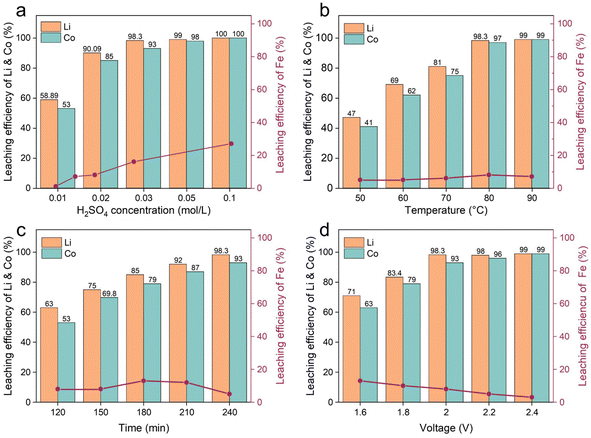
In this paper, we propose a process of paired electrolysis of LCO and LFP in a low-concentration H2SO4 solution. In a two-electrode system, LCO was used as the cathode, and LFP was used as the anode. When a voltage was applied, both Li+ and Co2+ from LCO and Li+ from LFP were leached into the H2SO4 solution, and FePO4 was obtained on the anode. By controlling the concentration of the H2SO4 solution, the dissolution of Fe was inhibited. The effects of different factors (e.g., the electrolyte concentration, electrolytic voltage, temperature, the mass ratio of the anode and cathode, etc.) on the leaching efficiency of Li+, Co2+ and Fe3+ were investigated. Moreover, the leaching kinetics of the anode and cathode were studied. To assess the feasibility of the paired electrolysis process, a primary economic and environmental analysis was conducted.
2. Experimental section
2.1. Pretreatment
The spent LFP batteries were bought from Taobao Marketplace, a Chinese website for online shopping, and the spent LCO batteries were obtained from the local second-hand cell phone market in Wuhan. Fig. 1 illustrates the full flow of the process, which mainly consists of three sections: pretreatment, paired electrolysis and precipitation. First, the remaining energy contained in the spent LCO and LFP batteries was fully discharged. The process involved soaking the spent batteries in a saturated sodium chloride (NaCl) solution for 24 h. Then, the completely discharged batteries were disassembled in a fume hood. After disassembly, we obtained the cathode, the anode, the diaphragm, the case, etc. Both LCO and LFP were operated in the same way. Then, the LCO cathode and LFP cathode were vacuum pyrolyzed in a tube furnace at 450 °C for 2 h to separate the active materials from the aluminum (Al) foils. Finally, the cathode powders of LCO and LFP were coated on a titanium (Ti) mesh by adding polyvinylidene fluoride (PVDF) and N-methyl-2-pyrrolidone (NMP) solvent to make the working electrodes, respectively. The digital images of the homemade LCO and LFP electrodes are shown in Fig. S1.†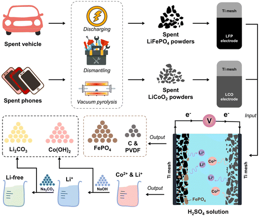 | ||
| Fig. 1 Schematic diagram of the process of the pre-treatment and the paired electrochemical recovery. | ||
2.2. Electrochemical behaviors of LCO and LFP
To investigate the electrochemical behavior of LCO and LFP in 0.03 M H2SO4, we employed linear sweep voltammetry (LSV) tests of LCO and LFP on an electrochemical workstation (ShanghaiChenhua, CHI760E), respectively. The information about the experimental setup, parameters, and procedures is shown in Fig. S2–6.† The working electrodes needed to be prepared before performing the electrochemical tests. Firstly, the titanium (Ti) mesh was thoroughly washed and then dried for 30 min. Secondly, a mixed slurry of LCO, conductive carbon and NMP (the mass ratio is 20![[thin space (1/6-em)]](https://www.rsc.org/images/entities/char_2009.gif) :
:![[thin space (1/6-em)]](https://www.rsc.org/images/entities/char_2009.gif) 1
1![[thin space (1/6-em)]](https://www.rsc.org/images/entities/char_2009.gif) :
:![[thin space (1/6-em)]](https://www.rsc.org/images/entities/char_2009.gif) 1) was coated on the Ti mesh (the payload mass is ∼2.0 mg cm−2) and then dried in an oven. The same treatment was applied to the LFP materials. The LSV tests of LCO and LFP were completed in a three-electrode-type cell, with the homemade LCO electrode and LFP electrode as the working electrodes. The reference electrode was Hg/HgSO4, while the counter electrode was a platinum (Pt) plate. The electrochemical behaviors of LCO and LFP were monitored in 0.03 M H2SO4 solution.
1) was coated on the Ti mesh (the payload mass is ∼2.0 mg cm−2) and then dried in an oven. The same treatment was applied to the LFP materials. The LSV tests of LCO and LFP were completed in a three-electrode-type cell, with the homemade LCO electrode and LFP electrode as the working electrodes. The reference electrode was Hg/HgSO4, while the counter electrode was a platinum (Pt) plate. The electrochemical behaviors of LCO and LFP were monitored in 0.03 M H2SO4 solution.
2.3. Paired electrolysis leaching of LCO and LFP
The paired electrolysis experiments of LCO and LFP were performed in a low-concentration sulfuric acid solution. A dual electrolysis system was used for constant voltage electrolysis, with LCO as the cathode and LFP as the anode, accompanied by magnetic stirring (240 rpm, model LC-MAS-HD, LICHEN). The effects of temperature, the mass ratio of LCO and LFP, the sulfuric acid concentration and electrolysis time on the leaching efficiency of Li and Co in LCO and Li and Fe in LFP were investigated.We used an atomic absorption spectrophotometer to monitor the content of Li, Co and Fe in the sampled solutions under different conditions. The leaching efficiencies of Li, Co and Fe were quantified using eqn (1):
 | (1) |
2.4. Analysis
The structures of the sample before and after paired electrolysis were characterized by X-ray diffraction (XRD, Shimadzu 6000 X-ray Diffraction Protocol) and X-ray photoelectron spectroscopy (XPS, Al Kα radiation, Thermo Scientific K-Alpha). The content of Co, Li and Fe of the electrolyte was detected by atomic absorption spectrophotometry (AAS3800). Morphologies of the products before and after paired electrolysis were analyzed by scanning electron microscopy (SEM, MIRA3 LMH), and the mapping of the elements was characterized by using an Aztec Energy X-Max 20 energy dispersive spectrometer (EDS).3. Results and discussion
3.1. Electrochemical measurements
The electrochemical reduction behaviors of LCO and the electrochemical oxidation behaviors of LFP in 0.03 M H2SO4 solution were revealed by using the LSV test. The LSV curves of LCO in 0.03 M H2SO4 solution (vs. Hg/HgSO4, all potentials refer to Hg/HgSO4 hereafter) are shown in Fig. 2a. The peak at ∼0.72 V matches the transformation of Co3+ to Co2+ in LCO. The LSV curve of the blank control electrode without coating LCO power has no reduction peak. Compared with the blank electrode without LFP coating, the oxidation peak of the LSV curve of the LFP coating (Fig. 2b) at ∼0.2 V corresponds to the conversion process of LFP to FePO4.36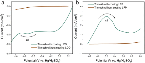 | ||
| Fig. 2 LSV curves of a Ti mesh with/without coating LCO (a) and a Ti mesh without coating LFP (b) at a scan rate of 1 mV s−1 in 0.03 M H2SO4 solution at room temperature. | ||
Therefore, the cathodic reaction of the paired electrolysis process of LCO can be expressed as eqn (2).
| LiCoO2 + 4H+ + e− → Li+ + Co2+ + 2H2O | (2) |
The anodic reaction of the paired electrolysis process of LFP can be expressed as eqn (3).
| LiFePO4 − e− → Li+ + FePO4 | (3) |
The overall reaction of the paired electrolysis can be expressed as eqn (4).
 | (4) |
3.2. Paired electrolysis of LCO and LFP
![[thin space (1/6-em)]](https://www.rsc.org/images/entities/char_2009.gif) :
:![[thin space (1/6-em)]](https://www.rsc.org/images/entities/char_2009.gif) LCO) over 1
LCO) over 1![[thin space (1/6-em)]](https://www.rsc.org/images/entities/char_2009.gif) :
:![[thin space (1/6-em)]](https://www.rsc.org/images/entities/char_2009.gif) 1, which does not match the result in eqn (4). Fig. S8† shows that the current of the LFP system is higher than LCO in two independent systems under the same conditions, and Fig. S9† shows that the electroresistance of the LCO electrode is smaller than LFP using a multimeter (DT9205A). Compared with the LCO electrode, the high current of the LFP electrode is attributed to the oxidation of LFP occurring more easily than the reduction of LCO. It is consistent with the delithiation process of LFP, which had a smaller activation energy (Fig. 8). This resulted in the dissolution of LCO accompanied by hydrogen evolution at the cathode, which increased the pH of the solution and inhibited the dissolution of FePO4.
1, which does not match the result in eqn (4). Fig. S8† shows that the current of the LFP system is higher than LCO in two independent systems under the same conditions, and Fig. S9† shows that the electroresistance of the LCO electrode is smaller than LFP using a multimeter (DT9205A). Compared with the LCO electrode, the high current of the LFP electrode is attributed to the oxidation of LFP occurring more easily than the reduction of LCO. It is consistent with the delithiation process of LFP, which had a smaller activation energy (Fig. 8). This resulted in the dissolution of LCO accompanied by hydrogen evolution at the cathode, which increased the pH of the solution and inhibited the dissolution of FePO4.
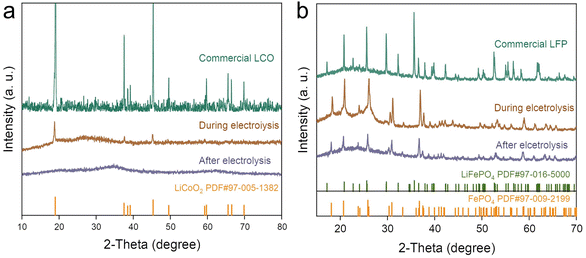
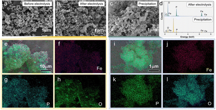
SEM images of the LFP material of paired electrolysis are shown in Fig. 5. After electrolysis, FePO4 had a similar morphology to that of LFP, but the particles became smaller (Fig. 5a and b). The pulverization of LFP particles was performed by using the mechanical stress of the de-lithium process. As shown in Fig. 5e–h, Fe, P, and O elements are evenly distributed in the whole structure of electrolysis products. The results of elemental analysis further confirm that the product is FePO4 (Fig. 5d), which is consistent with the previous XRD patterns of the product after electrolysis. Precipitation emerged in the same electrolyte with the cumulative electrolysis. The XRD patterns (Fig. S10†), SEM image (Fig. 5c) and the EDS mapping (Fig. 5i–l) signaled that the precipitate was PePO4, which is consistent with the result shown in Fig. 5d. This also indicated that Fe dissolved in solution can be separated by precipitation, so the concentration of Fe in the electrolyte was reduced.
The SEM images of LCO before, during and after electrolysis are shown in Fig. 6a–c. After electrolysis, the LCO particles completely leached out. Holes (Fig. 6d) were generated by the dissolution of LCO. Only the conductive carbon and binder remained on the electrode after electrolysis. No distribution of Li and Co was detected in the elemental mapping images (Fig. 6e–h) and elemental content analysis (Fig. 6i) of the electrolyzed materials due to the complete dissolution of LCO after electrolysis.
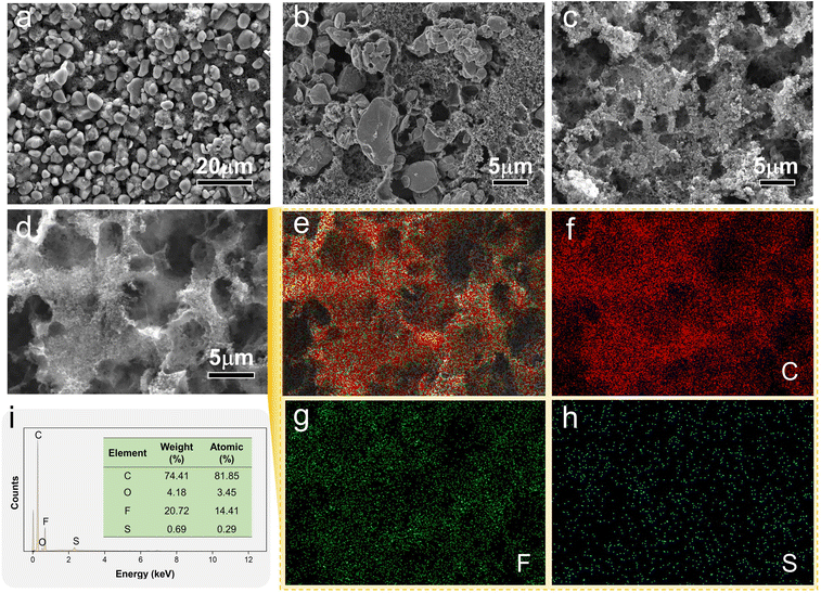 | ||
| Fig. 6 (a–c) SEM images of LCO before, during and after electrolysis, and the elemental mapping images of LCO after electrolysis (d–h) and elemental content analyses (i). | ||
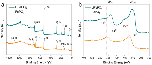
XPS measurements were applied to reveal the chemical states of LFP before and after paired electrolysis. As shown in Fig. 7a, the full spectrum of spent LFP materials demonstrates the presence of Li, Fe, O, P, and C elements. After electrolysis, the peak of Li was significantly reduced. Fig. 7b shows the Fe 2p spectra of LFP before and after electrolysis. The XPS fine spectrum of Fe 2p shows that the main peak is split into two components and two satellite peaks through spin–orbit coupling, which is consistent with previous reports.37 The binding energy position of the main peak in Fe 2p reveals the oxidation state of Fe. The shift of the spectrum peak can clarify the change of binding energy before and after, which compares the valence state transition of Fe. The Fe 2p fine spectrum of LFP before the electrolysis reaction showed that the maximum values of Fe 2p3/2 and Fe 2p1/2 peaks were at 710.5 eV and 724 eV. After electrolysis was completed, the Fe 2p fine spectrum of FePO4 showed that the maximum values of Fe 2p3/2 and Fe 2p1/2 peaks were 712.5 eV and 726 eV. Fig. 7b shows that Fe2+ is almost totally transformed into Fe3+ at the end of electrolysis. LCO was completely dissolved in the electrolyte, and it was not discussed in the context of XPS measurements.
3.3. Leaching kinetics
Leaching kinetics is the science of studying the rate and mechanism of the leaching process. The study of the kinetics of the paired electrolysis process allows for the identification of the control steps of the leaching process.38–40 The leaching kinetic processes of Li and Co for LCO and Li for LFP were explored in 0.03 M H2SO4 solution, at 2.4 V of different temperatures (40–80 °C). For solid–liquid reactions, the leaching process generally involves a surface chemical reaction control model (eqn (5)) and a residue layer diffusion control model (eqn (6)).41| 1 − (1 − x)1/3 = k1t, | (5) |
| 1 − 3(1 − x)2/3 + 2(1 − x) = k2t, | (6) |
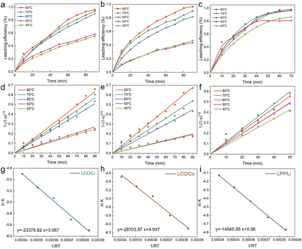
We explored the leaching processes of Li (Fig. 8a) and Co (Fig. 8b) of LCO and Li (Fig. 8c) of LFP at different temperatures at 2.4 V in a 0.03 M H2SO4 solution. The fitting of the experimental results showed that the leaching kinetics processes of Li (Fig. 8d) and Co (Fig. 8e) for LCO and Li for LFP (Fig. 8f) fit well to the surface chemical reaction control model, and the values of R2 of Li and Co of LCO were higher than 0.99 (Tables S1 and S2†). As for Li of LFP, the value of R2 was higher than 0.975 (Table S3†). The Arrhenius equation (eqn (7)) reflects the dependence of the rate constant on the temperature. The higher the activation energy (Ea), the faster the increase in the rate of reaction with increasing temperature.15,32,42 By applying a mathematical transformation to eqn (7), it can be equivalently transformed into eqn (8), and the Ea value of the reaction process can be calculated by mathematical fitting:
 | (7) |
ln![[thin space (1/6-em)]](https://www.rsc.org/images/entities/char_2009.gif) k = ln k = ln![[thin space (1/6-em)]](https://www.rsc.org/images/entities/char_2009.gif) A − Ea/RT, A − Ea/RT, | (8) |
After mathematical fitting and calculations, the Ea values were 23.38 and 28.70 kJ mol−1 for Li (Fig. 8g) and Co (Fig. 8h) of LCO, and 14.95 kJ mol−1 for Li of LFP (Fig. 8i). Based on the results of the fitting curves of LCO and LFP, the Ea value of the leaching reaction of LFP was smaller than that of LCO in the paired electrolysis process. This indicates that the leaching of LFP is theoretically easier than LCO. The results are consistent with the experimental results mentioned in the previous section, with regard to the molar ratio of LFP and LCO being higher than 1![[thin space (1/6-em)]](https://www.rsc.org/images/entities/char_2009.gif) :
:![[thin space (1/6-em)]](https://www.rsc.org/images/entities/char_2009.gif) 1.
1.
3.4. Economic and environmental evaluation of paired electrolysis
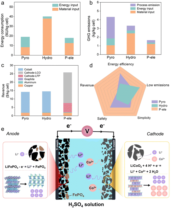
To quantify the environmental and economic advantages, we utilized the EverBatt model to evaluate the paired electrolysis process. The model consists of three primary modules: battery manufacture with virgin materials, battery recycling, and battery manufacture with recycled materials. In this process, we used the battery recycling module to evaluate the corresponding recycling process. The model comes with details for the commercial pyrometallurgy and commercial hydrometallurgy modules.43,44 Environmental impacts include process emissions (excluding emissions from fuel combustion) and environmental impacts of battery recycling. Cost includes revenue generated from the sales of recycled materials and the cost of the battery recycling plant operation (Fig. S11–13 and Tables S4 and 5†).45–47As shown in Fig. 9a, the energy consumption of commercial pyrometallurgy is mainly concentrated on the energy input (10.56 MJ kg−1 cell), while commercial hydrometallurgy is mainly concentrated on the material input (38.01 MJ kg−1 cell). The energy consumption of the paired electrolysis process is much lower than commercial hydrometallurgy, which is attributed to the lower material input (12.65 MJ kg−1 cell). As shown in Fig. 9b, the high-temperature process emissions of commercial pyrometallurgy dominate its greenhouse gas (GHG) emissions (4.32 kg kg−1 cell). The high chemical input of commercial hydrometallurgy dominates its GHG emissions (3.31 kg kg−1 cell), while the paired electrolysis process significantly reduces its GHG emissions (1.65 kg kg−1 cell) by its lower chemical and energy inputs. The products of the paired electrolysis process are Li2CO3, Co(OH)2 and FePO4, which can be used to directly regenerate LCO and LFP cells. As shown in Fig. 9c, the paired electrolysis process will yield the highest potential profit ($25.8 per kg per cell) compared to commercial pyrometallurgical and hydrometallurgical processes. However, the economic assessment of paired electrolysis recycling LCO and LFP based on the EverBatt model is only a reference for its prospective feasibility. The results are not precise because the paired electrolysis process has not been applied in industry. The paired electrolysis process requires neither high temperatures nor excessive chemical reagents. Combined with environmental and economic aspects, the paired electrolysis process is superior to pyrometallurgy and hydrometallurgy (Fig. 9d). Fig. 9e shows a schematic of the paired electrolysis process of LCO and LFP. It shows the process of dissolution of LCO on the cathode and the process of delithiation of LFP on the anode.
4. Conclusions
We demonstrated a paired electrolysis leaching method for repurposing Li, Co and FePO4 from LCO and LFP in a 0.03 M H2SO4 solution. When using a low concentration of H2SO4, the leaching efficiencies of Li and Co were above 98%, while the dissolution of Fe was limited to below 5% under the optimal conditions of 2.4 V, 80 °C and 0.03 M H2SO4 for 240 min. The utilization of H2SO4 was 83.3% and the current efficiency was 89.87%. According to the kinetic analysis, the Ea values were 23.38 and 28.70 kJ mol−1 for leaching Li and Co from LCO, and 14.95 kJ mol−1 for leaching Li from LFP. Apart from that, the electrons drive and act as reducing agents to dissolve LCO and enable the delithiation of LFP with minimized chemical agents. Economic and environmental evaluation illustrates this potential green technology in terms of energy efficiency, emissions, and safety of paired electrolysis.Author contributions
Huayi Yin directed the research. Huayi Yin and Jingjing Zhao designed the experiments. Jingjing Zhao and Fengyin Zhou carried out the experiments. Jingjing Zhao, Fengyin Zhou, Hongya Wang, Xin Qu, Danfeng Wang, Zhiyu Zheng, Yuqi Cai and Shuaibo Gao contributed to the results and discussion. Huayi Yin and Dihua Wang contributed to the supervision, resources and funding acquisition.Conflicts of interest
There are no conflicts to declare.Acknowledgements
We are greatly thankful for the financial support from the Fundamental Research Funds for the Central Universities (No. 2042023kf0214).References
- J. Lu, Y. Zhao, Y. Kang, C. Li, Y. Liu, L. Wang, H. Du, M. Fan, Y. Zhou, J. Wozny, T. Li, N. Tavajohi, F. Kang and B. Li, Carbon Energy, 2023, 5, e282 CrossRef CAS.
- X. Ma, L. Azhari and Y. Wang, Chem, 2021, 7, 2843–2847 CAS.
- Y. Lyu, X. Wu, K. Wang, Z. Feng, T. Cheng, Y. Liu, M. Wang, R. Chen, L. Xu, J. Zhou, Y. Lu and B. Guo, Adv. Energy Mater., 2021, 11, 2000982 CrossRef CAS.
- E. Fan, L. Li, Z. Wang, J. Lin, Y. Huang, Y. Yao, R. Chen and F. Wu, Chem. Rev., 2020, 120, 7020–7063 CrossRef CAS.
- S. Natarajan and V. Aravindan, Adv. Energy Mater., 2018, 8, 1802303 CrossRef.
- K. Xu, Nat. Energy, 2021, 6, 763–763 CrossRef CAS.
- J. Porzio and C. D. Scown, Adv. Energy Mater., 2021, 11, 2100771 CrossRef CAS.
- W. Yu, Y. Guo, S. Xu, Y. Yang, Y. Zhao and J. Zhang, Energy Storage Mater., 2023, 54, 172–220 CrossRef.
- X. Wu, J. Ma, J. Wang, X. Zhang, G. Zhou and Z. Liang, Global Challenges, 2022, 6, 2200067 CrossRef PubMed.
- L. Chang, A. Wei, S. Luo, S. Cao, X. Bi, W. Yang, R. Yang and J. Liu, Int. J. Energy Res., 2022, 46, 23145–23172 CrossRef CAS.
- M. Cao, Z. Liu, X. Zhang, L. Yang, S. Xu, S. Weng, S. Zhang, X. Li, Y. Li, T. Liu, Y. Gao, X. Wang, Z. Wang and L. Chen, Adv. Funct. Mater., 2023, 33, 2210032 CrossRef CAS.
- Recycle spent batteries, Nat. Energy, 2019, 4, 253, DOI:10.1038/s41560-019-0376-4.
- A. Mauger, M. Armand, C. M. Julien and K. Zaghib, J. Power Sources, 2017, 353, 333–342 CrossRef CAS.
- J. Ma, Y. Li, N. S. Grundish, J. B. Goodenough, Y. Chen, L. Guo, Z. Peng, X. Qi, F. Yang, L. Qie, C.-A. Wang, B. Huang, Z. Huang, L. Chen, D. Su, G. Wang, X. Peng, Z. Chen, J. Yang, S. He, X. Zhang, H. Yu, C. Fu, M. Jiang, W. Deng, C.-F. Sun, Q. Pan, Y. Tang, X. Li, X. Ji, F. Wan, Z. Niu, F. Lian, C. Wang, G. G. Wallace, M. Fan, Q. Meng, S. Xin, Y.-G. Guo and L.-J. Wan, J. Phys. D: Appl. Phys., 2021, 54, 183001 CrossRef CAS.
- H. Jin, J. Zhang, C. Yang, L. Ma, Y. Chen and C. Wang, Chem. Eng. J., 2023, 460, 141805 CrossRef CAS.
- Z. Wang, D. Wu, X. Wang, Y. Huang and X. Wu, Ind. Eng. Chem. Res., 2023, 62, 1181–1194 CrossRef CAS.
- X. Li, F. Zhou, S. Gao, J. Zhao, D. Wang and H. Yin, Waste Manage., 2022, 153, 347 CrossRef CAS.
- J. Zhao, J. Qu, X. Qu, S. Gao, D. Wang and H. Yin, Green Chem., 2022, 24, 6179–6188 RSC.
- J. Zhao, B. Zhang, H. Xie, J. Qu, X. Qu, P. Xing and H. Yin, Environ. Res., 2020, 181, 108803 CrossRef CAS PubMed.
- J. Yang, Y. Zhou, Z.-l. Zhang, K.-h. Xu, K. Zhang, Y.-q. Lai and L.-x. Jiang, Trans. Nonferrous Met. Soc. China, 2023, 33, 632–641 CrossRef CAS.
- G. Hu, Y. Gong, Z. Peng, K. Du, M. Huang, J. Wu, D. Guan, J. Zeng, B. Zhang and Y. Cao, ACS Sustainable Chem. Eng., 2022, 10, 11606–11616 CrossRef CAS.
- K. Du, E. H. Ang, X. Wu and Y. Liu, Energy Environ. Mater., 2022, 5, 1012–1036 CrossRef CAS.
- C. Erüst, A. Akcil, C. S. Gahan, A. Tuncuk and H. Deveci, J. Chem. Technol. Biotechnol., 2013, 88, 2115–2132 CrossRef.
- Y. Hong and M. Valix, J. Cleaner Prod., 2014, 65, 465–472 CrossRef CAS.
- B. Zhang, X. Qu, J. Qu, X. Chen, H. Xie, P. Xing, D. Wang and H. Yin, Green Chem., 2020, 22, 8633–8641 RSC.
- B. Zhang, H. Xie, B. Lu, X. Chen, P. Xing, J. Qu, Q. Song and H. Yin, ACS Sustainable Chem. Eng., 2019, 7, 13391–13399 CrossRef.
- J. Kong, S. Zhou, T. He, S. Gu and J. Yu, Green Chem., 2023, 25, 3956–3965 RSC.
- L. Yang, Z. Gao, T. Liu, M. Huang, G. Liu, Y. Feng, P. Shao and X. Luo, Environ. Sci. Technol., 2023, 57, 4591–4597 CrossRef PubMed.
- X. Li, S. Liu, J. Yang, Z. He, J. Zheng and Y. Li, Energy Storage Mater., 2023, 55, 606–630 CrossRef.
- H. Lv, H. Huang, C. Huang, Q. Gao, Z. Yang and W. Zhang, Appl. Catal., B, 2021, 283, 119634 CrossRef.
- K. Liu, S. Yang, F. Lai, H. Wang, Y. Huang, F. Zheng, S. Wang, X. Zhang and Q. Li, ACS Appl. Energy Mater., 2020, 3, 4767–4776 CrossRef CAS.
- Q. Meng, Y. Zhang and P. Dong, J. Cleaner Prod., 2018, 180, 64–70 CrossRef CAS.
- C. P. Makwarimba, M. Tang, Y. Peng, S. Lu, L. Zheng, Z. Zhao and A. G. Zhen, iScience, 2022, 25, 104321 CrossRef CAS PubMed.
- H. Li, S. Xing, Y. Liu, F. Li, H. Guo and G. Kuang, ACS Sustainable Chem. Eng., 2017, 5, 8017–8024 CrossRef CAS.
- W. Chu, Y. Zhang, L. Chen, K. Wu, Y. Huang and Y. Jia, Sep. Purif. Technol., 2021, 269, 118704 CrossRef CAS.
- X. Liu, X. Chen, Z. Zhao and X. Liang, Hydrometallurgy, 2014, 146, 24–28 CrossRef CAS.
- M. Maccario, L. Croguennec, A. Wattiaux, E. Suard, F. Lecras and C. Delmas, Solid State Ionics, 2008, 179, 2020–2026 CrossRef CAS.
- E.-y. Kim, M.-s. Kim, J.-c. Lee, J. Jeong and B. D. Pandey, Hydrometallurgy, 2011, 107, 124–132 CrossRef CAS.
- C. Stinn and A. Allanore, Nature, 2022, 602, 78–83 CrossRef CAS PubMed.
- H. Li, R. Fong, M. Woo, H. Ahmed, D.-H. Seo, R. Malik and J. Lee, Joule, 2022, 6, 53–91 CrossRef CAS.
- T. Or, S. W. D. Gourley, K. Kaliyappan, A. Yu and Z. Chen, Carbon Energy, 2020, 2, 6–43 CrossRef CAS.
- Y. Ma, X. Liu, X. Zhou, Y. He, J. Tang, F. Su, W. Yang, S. Fan, J. Wang, Z. Li and J. Yang, Chem. Eng. J., 2023, 451, 138535 CrossRef CAS.
- Q. Dai, J. Spangenberger, A. Shabbir, L. Gaines, J. C. Kelly and M. Wang, EverBatt: A Closed-loop Battery Recycling Cost and Environmental Impacts Model, Argonne National Laboratory, Energy Systems Division, Argonne, US, 2019 Search PubMed.
- M. Mohr, J. F. Peters, M. Baumann and M. Weil, J. Ind. Ecol., 2020, 24, 1310–1322 CrossRef CAS.
- B. Qiu, M. Liu, X. Qu, B. Zhang, H. Xie, D. Wang, L. Y. S. Lee and H. Yin, Environ. Sci. Technol., 2023, 57, 7599–7611 CrossRef CAS PubMed.
- F. Y. Zhou, X. Qu, Y. X. Wu, J. J. Zhao, S. B. Gao, D. H. Wang and H. Y. Yin, ACS Sustainable Chem. Eng., 2022, 10, 1287–1297 CrossRef CAS.
- F. Zhou, X. Li, S. Wang, X. Qu, J. Zhao, D. Wang, Z. Chen and H. Yin, J. Hazard. Mater., 2023, 459, 132150 CrossRef CAS PubMed.
Footnote |
| † Electronic supplementary information (ESI) available. See DOI: https://doi.org/10.1039/d3gc03322h |
| This journal is © The Royal Society of Chemistry 2024 |

