A novel high-entropy sulfide (ZnCoMnFeAlMg)9S8 as a low potential and long life electrocatalyst for overall water splitting in experiments and DFT analysis†
Shun
Li
a,
Likai
Tong
a,
Zhijian
Peng
 b,
Bo
Zhang
a and
Xiuli
Fu
 *a
*a
aSchool of Integrated Circuits, Beijing University of Posts and Telecommunications, Beijing 100876, P. R. China. E-mail: xiulifu@bupt.edu.cn; Fax: +86-10-62282054; Tel: +86-10-62282452
bSchool of Science, China University of Geosciences, Beijing 100083, P. R. China
First published on 23rd November 2023
Abstract
Sulfide compounds offer promising alternatives for electrocatalysts in water splitting, thanks to their diverse nature, intrinsic activities, affordability, and abundance in the Earth's crust. However, the limited active sites, hindered substance transport, larger particle size, and structural collapse restrict their performance in the electrolysis of water. In order to achieve a dual-functional catalyst with multiple catalytic sites, it is often necessary to construct heterogeneous or composite structures. However, this typically leads to an increase in catalyst resistance and also affects its operational stability. In response, we successfully prepared a high-entropy sulfide (ZnCoMnFeAlMg)9S8 through a low-temperature solvothermal method. This approach resulted in a reduction in grain size and a doubling of the specific surface area. The high entropy not only maintains the stability of the structure but also induces electron interactions within the catalyst through the interactions of multiple metals. This exposure of more active sites enables the realization of a dual-functional catalyst with multiple catalytic sites within a single structure. In addition, the increased presence of high-valence Fe and Ni ions promotes the chemisorption of intermediates, facilitating electron transfer during the reaction process. Benefiting from this multi-scale regulation strategy, the (ZnCoMnFeAlMg)9S8 displays an ultralow overpotential of 1.39 V at 10 mA cm−2 and a small Tafel slope of 35.3 mV dec−1. Density functional theory calculations indicate that high entropy can significantly modulate the local charge distribution and electronic properties of sulfides, thereby achieving optimal adsorption energy and reducing the potential energy barrier for hydrolysis. This study introduces a fresh approach to the functionalization of high entropy nanomaterials, while simultaneously enhancing the performance of water splitting catalysts.
1. Introduction
Over the past few decades, electrocatalytic water splitting has emerged as a potentially significant energy conversion technology that is both efficient and cost-effective, with the added benefit of contributing to environmental pollution reduction.1 However, the practical application of water electrolysis has been severely limited due to the lack of durable, low-cost, and highly active electrocatalysts with low overpotentials at high current densities. Water electrolysis includes the hydrogen evolution reaction (HER) and the oxygen evolution reaction (OER). The HER/OER reaction kinetics depends on the binding energy between the active site and the reaction intermediate, as well as the hydrolysis potential barrier. Nonetheless, the involvement of interfacial reactions, ion adsorption/desorption, and electron transfer in these two reactions can lead to suboptimal kinetic performance and increased overpotential.2Currently, commercial Pt/C serves as the most efficient catalyst for the HER, while Ru/Ir oxides exhibit excellent catalytic activity for the OER.3,4 However, the scarcity and high cost of Pt severely limit its application in water electrolysis. Recently, metal sulfide (MxSy) catalysts have emerged as promising candidates to fill this role due to their good electrical conductivity and potential for high activity. For example, MoS2,5 WS2,6 TaS2,7 and NbS2![[thin space (1/6-em)]](https://www.rsc.org/images/entities/char_2009.gif) 8 can be applied as HER electrocatalysts with excellent activity and stability. These layered structures well expose edge sites and have excellent electrical conductivity, which show remarkable intrinsic electrocatalytic HER activities. In the realm of the OER, numerous sulfides have demonstrated exceptional performance. Manjunatha et al. prepared cubic-phase NiS using the hydrothermal method, which demonstrated excellent OER performance with only 304 mV overpotential at 20 mA cm−2.9 However, due to the fact that the active sites for the HER and the OER are mostly different, in order to achieve better catalytic performance for overall water splitting, it is often necessary to construct heterogeneous structures or perform other interface engineering to increase the variety of active sites. On the basis of monophase sulfides, heterostructured Co9S8/WS2,10 Ir/MoS2,11 and CoS–Co(OH)2@MoS2+x
8 can be applied as HER electrocatalysts with excellent activity and stability. These layered structures well expose edge sites and have excellent electrical conductivity, which show remarkable intrinsic electrocatalytic HER activities. In the realm of the OER, numerous sulfides have demonstrated exceptional performance. Manjunatha et al. prepared cubic-phase NiS using the hydrothermal method, which demonstrated excellent OER performance with only 304 mV overpotential at 20 mA cm−2.9 However, due to the fact that the active sites for the HER and the OER are mostly different, in order to achieve better catalytic performance for overall water splitting, it is often necessary to construct heterogeneous structures or perform other interface engineering to increase the variety of active sites. On the basis of monophase sulfides, heterostructured Co9S8/WS2,10 Ir/MoS2,11 and CoS–Co(OH)2@MoS2+x![[thin space (1/6-em)]](https://www.rsc.org/images/entities/char_2009.gif) 12 have been developed, achieving excellent electrocatalytic performance in overall water splitting. What's more, Song et al. introduced a stable bifunctional metallic sulfide catalyst, Fe–Mo–S/Ni3S2@NF, supported on 3D nickel foam (NF). This catalyst exhibited exceptional stability over a 24-hour period and demonstrated remarkably low overpotentials: 141 mV for the HER at 100 mA cm−2 and 300 mV for the OER at 100 mA cm−2.13 Li et al. demonstrated the effectiveness of sophisticated polymetallic sulfide systems comprising 1T’-MoS2 and M9S8 (M = Co/Fe/Ni) as bifunctional nanotube-array electrodes for water splitting. These electrodes exhibited remarkably low overpotentials, with values of only 58 mV and 184 mV at 10 mA cm−2 for the HER and the OER, respectively. Importantly, these desirable performance characteristics were maintained over an extended period, indicating good long-term stability.14 Although this method has achieved multiple active sites, it is difficult to implement and has poorer stability compared to homogeneous materials, which undoubtedly hinders the industrial development of catalysts.
12 have been developed, achieving excellent electrocatalytic performance in overall water splitting. What's more, Song et al. introduced a stable bifunctional metallic sulfide catalyst, Fe–Mo–S/Ni3S2@NF, supported on 3D nickel foam (NF). This catalyst exhibited exceptional stability over a 24-hour period and demonstrated remarkably low overpotentials: 141 mV for the HER at 100 mA cm−2 and 300 mV for the OER at 100 mA cm−2.13 Li et al. demonstrated the effectiveness of sophisticated polymetallic sulfide systems comprising 1T’-MoS2 and M9S8 (M = Co/Fe/Ni) as bifunctional nanotube-array electrodes for water splitting. These electrodes exhibited remarkably low overpotentials, with values of only 58 mV and 184 mV at 10 mA cm−2 for the HER and the OER, respectively. Importantly, these desirable performance characteristics were maintained over an extended period, indicating good long-term stability.14 Although this method has achieved multiple active sites, it is difficult to implement and has poorer stability compared to homogeneous materials, which undoubtedly hinders the industrial development of catalysts.
In recent years, high-entropy materials have gradually become a research hotspot, and their diverse combinations of elements provide a new approach for constructing single-phase dual-functional catalysts. High-entropy sulfides (HESs) are single-phase solid solutions consisting of homogeneously mixed multicomponent metal sulfides containing at least five cations.15 Compared to bimetallic or trimetallic sulfides, HESs have the advantages of maximizing configuration entropy, providing excellent physical, chemical and mechanical properties such as outstanding stability, excellent temperature strength, and effective durability, which has attracted the interest of researchers in various fields.16 Additionally, HESs with multicomponent elements can regulate the charge state through synergistic effects, achieving compositional regulation of the optimum reaction intermediate adsorption and further improving water splitting activity, demonstrating good catalytic prospects.17 The high entropy effect resulting from the synergistic interactions of multiple components leads to the formation of numerous new active sites. This enables the achievement of dual-functional catalysts in a single-phase structure while simultaneously reducing the difficulty of catalyst preparation and enhancing catalyst life. However, there have been few reports on the synthesis of HMS so far, and the current synthetic strategy is complex, cumbersome, and expensive.
Based on the aforementioned arguments, this study synthesized a single-phase HES with active sites for both the OER and the HER using a mild solvothermal method. It is found that HES nanofragments exhibit superior OER and HER activities in alkaline media (1 mol L−1 KOH), which need an overpotential of 160 mV to drive 10 mA cm−2 for the OER and 170 mV to drive 10 mA cm−2 for the HER. Furthermore, this electrocatalyst not only exhibits an elevated intrinsic activity and higher reaction kinetics compared to the as-prepared Co9S8 catalyst, but the HES dual-functional catalyst also demonstrates a static voltage response at different current rates and superior ultralong stability at a high current rate of 250 mA cm−2. The superior performance of this material can be attributed to several factors. First, the successful doping of multiple metals allows for a greater movement of Fe and Ni ions to higher oxidation states, enhancing the chemical adsorption of water and further reducing the activation energy of intermediates. Second, the synergistic effect of multiple metals greatly improves the conductivity of the material, thereby further enhancing its electrochemical activity. Lastly, the doubling of the specific surface area and the reduction in grain size increase the contact area with water and reaction sites. The water adsorption energy and Gibbs free energy of hydrogen adsorption in HESs and Co9S8 materials were calculated using density functional theory (DFT). The calculations reveal that HESs exhibit stronger adsorption energy and a lower overpotential for water and intermediate hydrogen adsorption due to the modulation of their electronic structure.
2. Experimental details
2.1 Chemicals and materials
The following chemical reagents were used: cobalt acetate tetrahydrate (C4H6CoO4·4H2O, 99.0+%), iron acetate (C4H6O4Fe, 99.0+%), manganese acetate tetrahydrate (C4H6O4Mn·4H2O, 99.0+%), zinc acetate dihydrate (C4H6O4Zn·2H2O, 99.0+%), aluminum chloride hexahydrate (AlCl3·6H2O, 98.0+%), magnesium acetate tetrahydrate (C4H6O4Mg·4H2O, 99.0+%), thiourea (CH4N2S, 99.0+%), and ethylene glycol (C2H6O2, 98.0+%). All chemicals were purchased from Sinopharm Chemical Reagent Co., Ltd (Shanghai, China) and were used without additional purification. Nickel foam (NF, 0.2 cm thickness) was used as the substrate.2.2 Preparation of electrocatalysts
In the initial step, 0.0047 mol of C4H6O4Co·4H2O, C4H6O4Fe, C4H6O4Mn·4H2O, C4H6O4Zn·2H2O, AlCl3·6H2O, and C4H6O4Mg·4H2O were individually dissolved in 80 mL of C2H6O2. Subsequently, 2.1312 g of CH4N2S was added to the preceding solution and stirred magnetically for 30 min. The resulting solution was then transferred to a Teflon-lined stainless-steel autoclave with a volume of 100 mL. The autoclave was subsequently sealed and subjected to heating at 200 °C for 48 h in an open oven. After cooling to room temperature, the solid products were collected, centrifuged, and subjected to three washing cycles with deionized water. Subsequently, the collected solid products were vacuum dried at 60 °C for 3 h to obtain (ZnCoMnFeAlMg)9S8. As control tests, Co9S8 was synthesized using the same hydrothermal process but with only the addition of C4H6O4Co·4H2O.The (ZnCoMnFeAlMg)9S8/NF and Co9S8/NF electrodes were prepared using a straightforward procedure. Initially, 5 mg of (ZnCoMnFeAlMg)9S8 was added to 0.9 mL of pure Nafion solution and mixed with 1 mL of 5% ethanol solution to obtain a homogeneous ink solution. Ultrasonic treatment was applied to this mixture for 30 min to ensure uniformity. Subsequently, 200 μL of the resulting solution was drop-cast on the pretreated NF, and the (ZnCoMnFeAlMg)9S8/NF electrode was obtained by drying the coated NF. The commercial Co9S8/NF electrode was also prepared using the same method.
2.3 Sample characterization
To analyze the samples, an X-ray diffractometer (XRD, Bruker D8 Advance, Germany) equipped with Cu Kα radiation (λ = (0.154 nm)) was employed to determine their crystalline structures and phase compositions. Scanning electron microscopy (SEM, Gemini SEM 500, Düsseldorf, Germany) was utilized to examine the morphology and microstructures. The coordination environment and valence state of elements in the products were examined through X-ray photoelectron spectroscopy (XPS) analysis (utilizing XPS, Waltham, MA, USA). The XPS spectra were calibrated by referencing the C 1s signal at 284.8 eV and analyzed using XPSPeak41 software for precise fitting. Inductively coupled plasma optical emission spectroscopy (ICP-OES) was employed for element quantification, utilizing the iCAP 7600DUO instrument manufactured by Thermo Fisher Scientific. The specific surface area was determined using the ASAP2460 instrument from Micromeritics Instrument Corporation (BET, USA), with nitrogen gas as the adsorbate, according to the Brunauer–Emmett–Teller (BET) method. Oxygen vacancies in the samples were detected via electron paramagnetic resonance spectrometry (EPR), employing the EMXnano instrument from Bruker (Germany).2.4 Electrochemical evaluation
The OER activities of the catalysts were evaluated via an electrochemical workstation (CHI660E, Chenhua Instrument, Shanghai, China) featuring a standard three-electrode system comprising a working electrode, a Hg/HgO reference electrode, and a carbon rod counter electrode. The electrocatalysts were first cut into 1 × 2 cm2 pieces to prepare the working electrodes, with the immersed part in the 1.0 mol L−1 KOH electrolyte maintained at 1 × 1 cm2. Stable polarization curves for the HER/OER were obtained through multiple cyclic voltammetry (CV) scans within the appropriate potential range. Linear sweep voltammetry (LSV), with a sweep rate of 2 mV s−1, was used to record the polarization curves. Electrochemical impedance spectroscopy (EIS) was performed within a frequency range of 105 to 10−2 Hz. All potentials were calibrated relative to the reversible hydrogen electrode (RHE) using the following equation:| ERHE = EHg/Hgo + 0.059 × pH + 0.098 (V) | (1) |
In 1.0 mol L−1 KOH, pH = ∼14. iR compensation was implemented for all the curves using eqn (2),
| V = VRHE − iRs | (2) |
The electrochemically active surface area (ECSA) of the samples was estimated using a calculation method described in ref. 18, based on the different CV curve data,
| ECSA = Cdl/Cs | (3) |
2.5 DFT calculation details
All first-principles-based DFT calculations were performed using the Vienna ab initio simulation package (VASP 5.4.4).19 As for the HES, a Hubbard U (DFT+U) term was added, which could improve the description of HER and OER activities.20 The DFT+U method with U values of 3.5 for Mn, 4.3 for Fe, and 3.5 for Co was employed for a more accurate description of the samples.21 All-electron projector augmented wave (PAW) pseudopotentials were used to describe the electron–ion interactions. The Perdew–Burke–Ernzerhof (PBE) functional of the generalized gradient approximation (GGA) was utilized to approximate the electronic exchange and correlation.22 The convergence criteria for the maximum force were set at 0.01 eV Å−1. A plane wave basis with an energy cut-off of 500 eV was employed. For modeling doping systems, the HES structures were generated using a Co9S8 (4 4 0) supercell. To prevent any interaction between supercells, a vacuum zone of 15 Å was introduced along the z-direction.In an alkaline medium, the four-electron OER process can be described as follows:23
| H2O + * → *HO + H+ + e− | (4) |
| *HO ↔ *O + *H + *e | (5) |
| *O + H2O ↔ *HOO + H+ + e+ | (6) |
| *HOO ↔ * + O2 + H+ + e− | (7) |
| ΔGi = ΔE + ΔZPE − TΔS − e∅ | (8) |
The total energy difference (ΔE) between the reactant and product molecules in the reactions is calculated using eqn (4)–(7). This includes the changes in zero-point energy (ΔZPE) and the entropic contribution (TΔS). The charge transferred (e) and the external potential (∅) are also taken into account. All reaction free energies (ΔGi) were determined using DFT calculations under standard conditions (∅ = 0, T = 298.15 K).
Similarly, the three steps of the HER process under alkaline conditions are considered to explore the electrocatalyst properties of (ZnCoMnFeAlMg)9S8 and Co9S8.
| H2O + * + e− → OH− + H* | (9) |
| H* + H2O + e− → OH− + H2 | (10) |
| H* + H* → H2 | (11) |
3. Results and discussion
3.1 Composition and structure
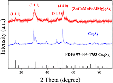
XRD measurements were carried out to study the structures of the materials. As shown in Fig. 1, two samples exhibited high crystallinity and good conformity with the structure of standard Co9S8 (PDF#97-003-1753), with no observed peaks of other substances. This shows how multiple metals can be added to the lattice, replacing some of the Co, to create a single-phase metal sulfide instead of separate binary sulfides. This provides initial proof for the formation of an HES. Furthermore, we refined the XRD results of the HES (Fig. S1†) and listed the atomic coordinates in Table S1.† As the morphology of catalysts plays a crucial role in determining catalytic performance, we investigated the morphology of the HES using SEM. As shown in Fig. 2(a), Co9S8 exhibits a regular nanosphere morphology with a diameter ranging from 400 to 1000 nm. The partially incomplete nanospheres depicted in the higher magnification image in Fig. 2b indicate that the interior of the spheres is hollow, suggesting that during the hydrothermal reaction, Co9S8 should generate hollow nanosphere shell structures. However, the HES compounds, as revealed in Fig. 2c and d, clearly demonstrate the absence of the spherical shell morphology, which fractures into smaller two-dimensional nanoplate structures with dimensions mostly in the tens of nanometers. This is attributed to the disparate diffusion rates of multiple metal ions during crystal growth. This not only significantly reduces the size of the nanomaterials but also effectively doubles the surface area, promoting better contact with the electrolyte during the reaction process and enhancing catalytic performance. Further structural analysis was conducted using TEM. Fig. S2† shows the TEM image, indicating that (ZnCoMnFeAlMg)9S8 has a two-dimensional nanosheet structure. HRTEM analysis of the clear lattice stripes (Fig. 2(e)) and the corresponding SAED pattern (Fig. 2(e)) reveal that adjacent lattice stripes with 1.76 Å and 5.80 Å spacing correspond to the (4 4 0) and (1 1 1) crystal planes of (ZnCoMnFeAlMg)9S8. The measured crystal planes here are fully consistent with the crystal planes corresponding to the strongest peaks in the XRD results, further confirming the successful synthesis of a highly crystalline HES. In order to demonstrate that the nanosheets of the HES are formed by the rupture of hollow Co9S8 spheres during the reaction process, the specific surface areas of both were measured. The results in Fig. 2(f) indicate that the specific surface area of (ZnCoMnFeAlMg)9S8 (7.2581 m2 g−1) is nearly twice that of Co9S8 (4.8091 m2 g−1), providing evidence that the hollow spheres double their surface area after rupturing into nanofragments. This phenomenon enhances the contact between the HES and the electrolyte, thereby promoting a more thorough reaction and improving the catalytic efficiency.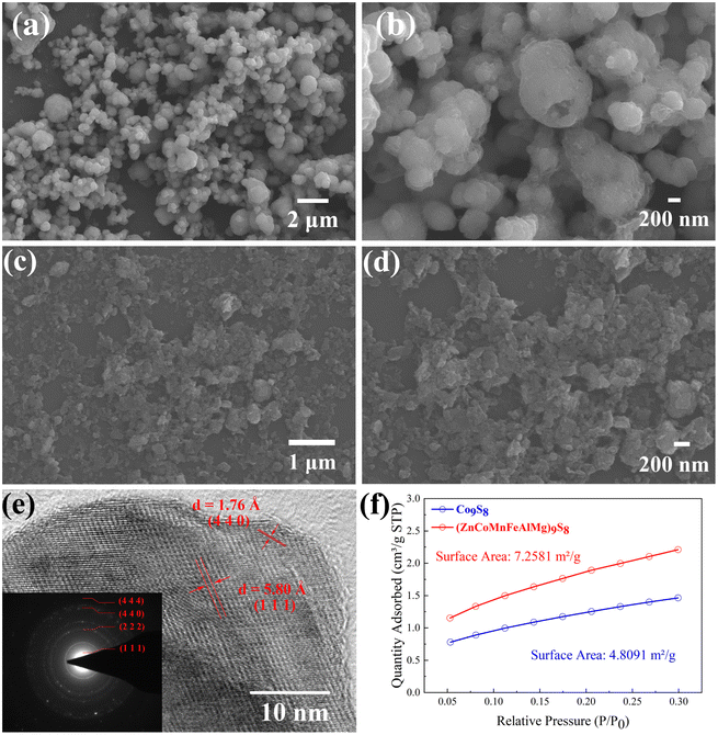 | ||
| Fig. 2 SEM images of (a and b) Co9S8 and (c and d) (ZnCoMnFeAlMg)9S8. (e) HRTEM image and the SAED pattern of (ZnCoMnFeAlMg)9S8. (f) N2 adsorption–desorption isotherm. | ||
We conducted SEM-EDX mapping scans to further investigate the distribution of elements in the HES, and the results are shown in Fig. 3. Among them, Fig. 3(a) shows the SEM image where the SEM-EDX mapping scanning was carried out, and Fig. 3(b–h) display the recorded images of all the elements. At the nanometer scale, all elements exhibit a homogeneous distribution without any signs of segregation. This homogeneity enables them to function as independent catalytically active centers. Meanwhile, to maximize the structural entropy, it is essential to ensure that all transition metals in the HES are present in equimolar or nearly equimolar ratios. We quantitatively analyzed the metal element content in (ZnCoMnFeAlMg)9S8 by ICP-OES, and the results are shown in Fig. 3(i). The results demonstrate that the content of various metallic elements is approximately equal. Considering the previously measured uniform distribution of elements, it can be inferred that the successful synthesis of the HES (ZnCoMnFeAlMg)9S8 was achieved by substituting a portion of Co in Co9S8 with multiple metals.
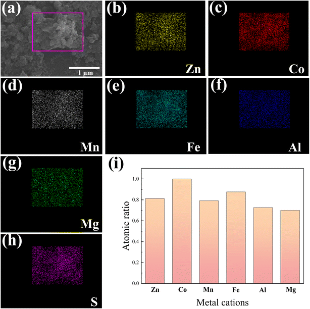 | ||
| Fig. 3 SEM-EDX mapping scanning area (a) and (b–h) the recorded mapping images of Zn, Co, Mn, Fe, Al, Mg, and S in (ZnCoMnFeAlMg)9S8. (i) The proportion of metal elements measured by ICP-OES. | ||
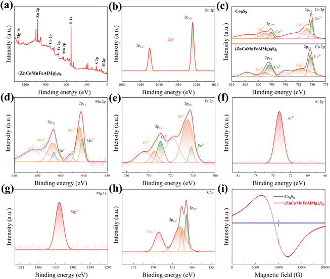
Due to the significant impact of the electronic structure on the catalytic properties of materials, we investigated the chemical states and elemental composition in the surface regions of (ZnCoMnFeAlMg)9S8 and Co9S8 using XPS. The corresponding survey spectrum can be seen in Fig. 4(a) and Fig. S3(a).† In brief, the spectrum indicates the presence of zinc (Zn 2p), cobalt (Co 2p), manganese (Mn 2p), iron (Fe 2p), aluminum (Al 2p), magnesium (Mg 1s), sulfur (S 2p), and oxygen (O 1s). As seen in Fig. 4(b), in the high-resolution spectrum of Zn 2p, there are two sharp peaks located at 1021.99 (Zn 2p3/2) and 1045.1 eV (Zn 2p1/2), where the Zn 2p3/2 spectrum can be attributed to Zn2+.24 Furthermore, two spin–orbit double peaks and two satellite peaks are presented in the Co 2p spectrum of (ZnCoMnFeAlMg)9S8 (Fig. 4(c)). The peaks at 780.68 and 795.95 eV are attributed to Co3+, while the peaks at 783.94 and 797.76 eV correspond to Co2+. The double peaks located at 790.33 and 804.16 eV belong to the satellite peaks.25 Additionally, it is noteworthy that the peaks of Co2+ and Co3+ in the HES are shifted towards higher binding energy compared to the peaks of Co2+ and Co3+ in Co9S8, indicating the presence of electron-withdrawing groups around these atoms. Moreover, this also demonstrates that high entropy effects lead to changes in the local electronic environment around the metal atoms, resulting in an increase in free electrons. In the high-resolution spectrum of Mn 2p (Fig. 4(d)), two peaks at 641.37 and 653.18 eV belong to Mn 2p3/2 and Mn 2p1/2, respectively. They can be deconvoluted into four peaks, with two peaks, 641.89 and 653.52 eV, belonging to Mn3+ and another two peaks, 640.72 and 652.91 eV, belonging to Mn2+.26 The high-resolution Fe 2p core-level spectrum is depicted in Fig. 4(e). The peaks at 710.46 and 723.08 eV correspond to Fe 2p3/2 and Fe 2p1/2 of Fe2+ in (ZnCoMnFeAlMg)9S8, respectively. Additionally, the peaks at 712.72 and 725.24 eV can be attributed to Fe 2p3/2 and Fe 2p1/2 of Fe3+ in (ZnCoMnFeAlMg)9S8. The satellite peaks are observed at 715.68 and 718.63 eV.27,28 The coexistence of Mn2+, Mn3+, Fe2+, and Fe3+ may accelerate the kinetics of the redox reactions, which is beneficial for improving the OER and HER performance. The high-resolution Al 2p spectrum, as shown in Fig. 4(f), exhibits a prominent, well-defined peak at 74.2 eV. This peak corresponds to Al 2p3/2 of Al3+ in the sample and is in good agreement with the value reported in ref. 29. The high-resolution Mg 1s spectrum is presented in Fig. 4(g), where the peak located at 1304.36 eV can be attributed to the bivalent state of Mg2+. This value is consistent with the previously reported value in ref. 24. In addition to the metallic elements, the S 2p spectrum of (ZnCoMnFeAlMg)9S8 shown in Fig. 4(h) indicates the dominance of S2− and bridging S22− species, confirming the formation of an HES. Besides, a small amount of SO42− ions can be detected, which combines with multivalent metal species to enhance the overall water splitting performance.30 The situation of S ions in Co9S8 is also similar to that in (ZnCoMnFeAlMg)9S8 (Fig. S2(b)†).
XPS research shows that there are multiple valence metal ions on the surface of nano fragments. To reveal the spin states of those metal ions, EPR measurements were performed (Fig. 4(i)) because it was earlier revealed that the spin states of active atoms are substantial factors in enhancing catalytic activity and EPR is a powerful technique for detecting the 3d electron configuration (both eg and t2g electrons).31–33 When measured under room conditions, both the (ZnCoMnFeAlMg)9S8 and Co9S8 samples exhibited asymmetrical broad resonance lines in their EPR spectra. In the case of Co9S8, only a small peak was observed, which can be attributed to the presence of free electrons from sulfur atoms. Interestingly, no uncoupled cobalt ion signal was observed at ∼6000 g, indicating the coupling of cobalt ions with surrounding cobalt or sulfur ion electrons. However, for (ZnCoMnFeAlMg)9S8, besides the peak from sulfur electrons, a broader and stronger peak was clearly visible. This can be attributed to the synergistic interaction of multiple metals in a high-entropy environment, which alters the local electron distribution and results in the presence of a large number of free electrons around the metal cations, thus, confirming the existence of the high-spin configuration of multi-valent metals, which is beneficial for OER and HER activities.31
3.2 Electrocatalytic performances
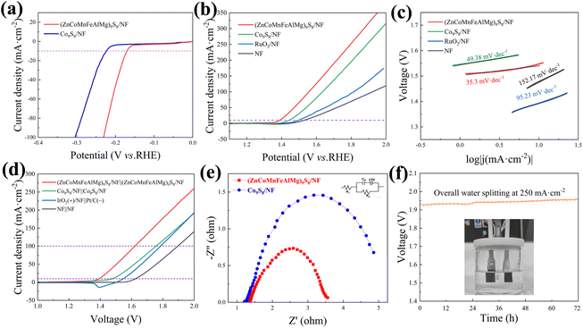
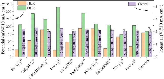
The electrocatalytic performance of (ZnCoMnFeAlMg)9S8/NF for water splitting was initially assessed under alkaline conditions (1.0 M KOH) and at room temperature using a three-electrode configuration cell. Fig. 5(a) illustrates the polarization curves for (ZnCoMnFeAlMg)9S8/NF and Co9S8/NF, with iR loss correction, during the HER. Remarkably, the (ZnCoMnFeAlMg)9S8/NF catalyst demonstrates a lower onset overpotential (0.14 V) compared to Co9S8/NF (0.19 V). Additionally, the cathodic current density increases rapidly under more negative potentials beyond the onset overpotential. Notably, the (ZnCoMnFeAlMg)9S8/NF catalyst only requires a small overpotential of 170 mV to achieve a current density of 10 mA cm−2, which is a common criterion for evaluating water splitting activity. The OER performance of (ZnCoMnFeAlMg)9S8/NF, which serves as another crucial water splitting half-reaction, was evaluated in a 1 M KOH electrolyte. The corresponding results are presented in Fig. 5(b), demonstrating that (ZnCoMnFeAlMg)9S8/NF achieved a current density of 10 mA cm−2 with an overpotential of only 160 mV. This performance surpassed that of Co9S8/NF (η10 = 213 mV), bare NF (η10 = 300 mV), and commercial RuO2 on NF (η10 = 269 mV). The (ZnCoMnFeAlMg)9S8/NF also showed better catalytic activity at higher current densities, indicating that the co-doping of multiple metallic elements has a synergistic effect on improving the OER performance. The Tafel slope, obtained from the LSV curves, is widely recognized as a significant parameter that reflects the reaction kinetics. The (ZnCoMnFeAlMg)9S8/NF catalyst had a minor Tafel slope (35.3 mV dec−1) and exhibited superior OER kinetics to Co9S8/NF (49.38 mV dec−1), bare NF (152.17 mV dec−1), and RuO2/NF (95.23 mV dec−1) (Fig. 5(c)).The outstanding bifunctional activity of (ZnCoMnFeAlMg)9S8 was expected to convert into excellent electrolyzer performance. Interestingly, using (ZnCoMnFeAlMg)9S8/NF as the electrode catalyst for total water splitting delivered a current density of 10 mA cm−2 at only 159 mV and 100 mA cm−2 at only 393 mV, outperforming the commercial IrO2/NF||Pt/C catalyst by 133 mV at 100 mA cm−2 (Fig. 5(d)). Furthermore, the number of active sites exposed by the catalysts was evaluated using the ECSA. As shown in Fig. S4,† (ZnCoMnFeAlMg)9S/NF exhibited a higher value (90.51 mF cm−2) compared to Co9S8/NF (29.59 mF cm−2). The increased ECSA may be attributed to the formation of additional active sites that originated from the incorporation of Zn, Mn, Fe, Al, and Mg into Co9S8 by adjusting the catalytic properties,34 which is consistent with the SEM and BET results. This further supports the notion that HES phases have more active sites than Co9S8. Furthermore, in order to examine the kinetics of the HER and the OER at the electrode/electrolyte interface, EIS analysis was conducted (Fig. 5(e)). The inset figure in Fig. 5(e) displays the fitted equivalent circuit for the Nyquist plot of the (ZnCoMnFeAlMg)9S8/NF electrocatalyst using ZView software. The diameter of the semicircular part in the curve of (ZnCoMnFeAlMg)9S8/NF is smaller than that of Co9S8/NF, indicating that the charge transfer resistance of (ZnCoMnFeAlMg)9S8/NF is smaller.34 A reduced charge transfer resistance facilitates the efficient transfer of charge between the electrolyte and the electrocatalyst, thereby enhancing the reaction kinetics. In order to bring the catalyst closer to industrial applications, we conducted a long-term stability test on the catalyst under high current. The (ZnCoMnFeAlMg)9S8/NF was extraordinarily robust in electrolyzers wherein it could be stably operated for 72 h without an obvious increase of the overpotential (Fig. 5(f)). During the water splitting process, the electrodes show a consistent generation of dense bubbles. The enhanced electrochemical catalytic performance of the electrode is evident from this observation. Then, we conducted material characterization following long-term cycling tests using XRD and XPS techniques, as shown in Fig. S5 and S6.† The XRD results verify the high structural stability of the catalyst, with no apparent phase changes observed, which highlights the superior stability of the high-entropy materials. The XPS results indicate an observable increase in the O 1s peak, indicating oxidation, while the other metal elements show no significant change. This suggests good reversibility and high stability of the materials during the electrocatalytic process. These additions significantly enhance the scientific rigor of our study, providing a more comprehensive analysis of the redox reactions and material characterization. In addition, we compared the electrocatalytic performance of the catalyst used in this study with commonly used commercial catalysts and advanced sulfur-based catalysts (Table S2†).6,35–43 The overall water splitting performance of the catalyst in this study surpasses that of recently reported sulfide-based dual-functional electrocatalysts (Fig. 6).38,39,44–51
To further investigate the roles of each component in the catalyst, we designed and conducted a series of comparative experiments. By selectively removing specific elements from the high-entropy catalyst, we synthesized six different HESs. Subsequently, we tested the overpotential and stability of these HESs for electrocatalytic water decomposition, as demonstrated in Fig. S7 and S8.† Fig. S7† illustrates the EDS analysis results of the six materials, revealing their elemental composition in comparison with the experimentally obtained hexa-elemental HES. It is evident that the six materials lack the elements Zn, Co, Mn, Fe, Al, and Mg, respectively. By comparing the water decomposition performance given in Fig. S8,† it is observed that the two materials lacking Co or Fe exhibit higher overall overpotentials. However, after a 72 h test period, the overall trend shows minimal changes, indicating good catalyst stability. On the other hand, the two materials lacking Mg or Al elements demonstrate lower initial overpotentials but experience significant voltage fluctuations over prolonged operation. Therefore, it can be reasonably inferred that Co and Fe elements exhibit stronger activity, leading to more pronounced catalytic enhancement, while Al and Mg elements primarily contribute to improving catalyst stability.
3.3 Theoretical studies
To gain a better understanding of the superior electrochemical performance exhibited by (ZnCoMnFeAlMg)9S8, DFT simulations were conducted. Theoretical models of Co9S8 and (ZnCoMnFeAlMg)9S8 were constructed for this purpose (Fig. 7(a and b)). We calculated and compared the total density of states (TDOS) and the partial wave density of states (PDOS) for both cases. The results are shown in Fig. 7(c and d). The TDOS analysis of (ZnCoMnFeAlMg)9S8 indicated a metallic character with significantly higher DOS near the Fermi level compared to Co9S8. This observation suggests that the high-entropy effect at the interface enhances the carrier concentration and conductivity of the material.52 In the PDOS of Co9S8, the PDOS of Fe and Co at the Fermi level is significantly enhanced, which also proves that the increase in free electrons around Fe and Co enhances electron conduction, consistent with the previous XPS and EPR results. In order to further elucidate the fundamental mechanism behind the excellent water splitting activity of high-entropy treatment and to understand the charge transfer at the interfaces of (ZnCoMnFeAlMg)9S8 and Co9S8, we calculated the differential charge density for both. The results are shown in Fig. S9 and S10,† with blue representing charge accumulation and yellow representing charge loss. It is evident that during the intermediate adsorption process, (ZnCoMnFeAlMg)9S8 exhibits more charge transfer than Co9S8, with the majority being concentrated near Fe and Co, indicating that the adsorption sites have higher catalytic activity.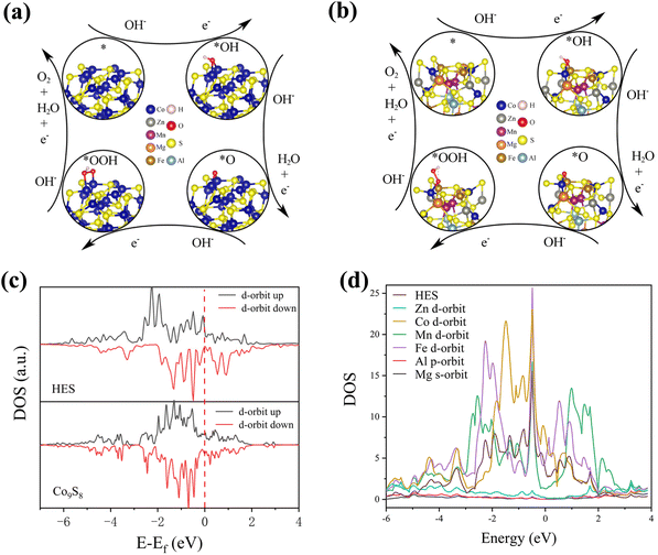 | ||
| Fig. 7 Schematic diagram of the model of the OER process: (a) Co9S8 catalyst and (b) (ZnCoMnFeAlMg)9S8; (c) TDOS of the d-orbitals for (ZnCoMnFeAlMg)9S8 and Co9S8; (d) PDOS of (ZnCoMnFeAlMg)9S8. | ||
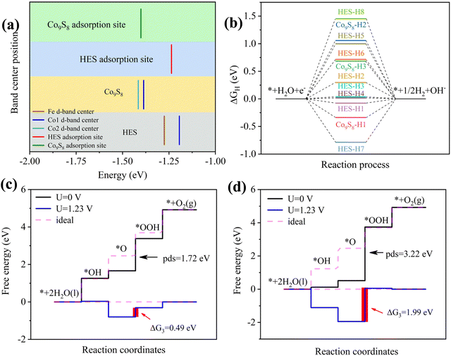
The d-band center is commonly used to characterize the reactivity of active sites towards reaction intermediates. Fig. 8(a) demonstrates an increased d-band center, shifting from −1.4 eV for Co9S8 to −1.23 eV for (ZnCoMnFeAlMg)9S8, indicating a potentially reduced interaction between the adsorbed oxygen species and the active site. This enhancement promotes efficient dissociation during the OER process.53,54 Contrasting the main active site Co by the d-band center, it is also observed that there is a significant enhancement in the HES, which demonstrates that the overall improvement in the performance of the HES is not solely attributed to a single element with outstanding properties, but rather to the synergistic effect resulting in an increase in the number of active sites and catalytic performance. It is well known that a moderate value with ΔGH* ≈ 0 eV is conducive to hydrogen generation.55,56 As shown in Tables S3 and S4,† ΔG of the active hydrogen adsorption step during the HER was calculated at various adsorption sites, and the results are depicted in Fig. 8(b). The ΔGH* value (0.017 eV) for (ZnCoMnFeAlMg)9S8 is notably closer to 0 eV compared to Co9S8 (−0.337 eV), indicating its enhanced catalytic activity for the HER. Furthermore, Fig. 8(c and d) illustrate the ΔG values for the adsorption of OER intermediates. As the OER involves a more complex four-electron reaction, the ΔG values for its intermediates HO*, O*, and HOO* differ. Notably, when comparing the decisive step (O* to OOH*), it becomes evident that (ZnCoMnFeAlMg)9S8 exhibits superior catalytic performance for the OER. This observation further supports the idea that high-entropy synergy effects at heterogeneous interfaces optimize the electronic structure, reduce reaction energy barriers, and thereby improve catalytic performance. In summary, it is believed that the presence of multiple active sites on the surface can effectively modify the electronic state, facilitating charge transfer and optimizing the adsorption/desorption of intermediates. This comprehensive enhancement contributes to improvements in both the thermodynamic and kinetic aspects of the HER and OER semi-reactions.
4. Conclusions
In summary, we propose a more robust and efficient bifunctional electrocatalyst (ZnCoMnFeAlMg)9S8. By leveraging the synergistic effects of multiple metals in (ZnCoMnFeAlMg)9S8, we construct multiple active sites within the same crystal lattice, thereby avoiding the instability issues observed in most bifunctional catalysts due to heterogeneous structures during high-current and long-term operation. Additionally, the increased variety of metals leads to changes in the local electron distribution, resulting in an increase in free electrons around high-valence metal sites. This not only enhances the conductivity but also facilitates the transfer of intermediates. As a result, (ZnCoMnFeAlMg)9S8 exhibits excellent overall water splitting performance, as evidenced by its smaller voltage (1.39 V) to afford a current density of 10 mA cm−2. Through a series of experimental characterization studies and DFT calculations, the reasons behind these exceptional properties are revealed. The straightforward synthesis method and outstanding catalytic performance position (ZnCoMnFeAlMg)9S8 as a promising bifunctional catalyst that can be widely applied in hydrogen production and other electrochemical energy devices for overall water splitting.Conflicts of interest
There are no conflicts to declare.Acknowledgements
This work was supported by the open research fund of Songshan Lake Materials Laboratory (2023SLABFK10) and the National Natural Science Foundation of China (Grant No. 12174035 and U21A6004).References
- Y. Yang, H. Q. Yao, Z. H. Yu, S. M. Islam, H. Y. He, M. W. Yuan, Y. H. Yue, K. Xu, W. C. Hao, G. B. Sun, H. F. Li, S. L. Ma, P. Zapol and M. G. Kanatzidis, J. Am. Chem. Soc., 2019, 141, 10417–10430, DOI:10.1021/jacs.9b04492
.
- J. Li, G. S. Li, J. H. Wang, C. L. Xue, X. S. Li, S. Wang, B. Q. Han, M. Yang and L. P. Li, Inorg. Chem. Front., 2020, 7, 191–197, 10.1039/C9QI01080G
.
- D. C. Nguyen, T. L. L. Doan, S. Prabhakaran, D. T. Tran, D. Kim, J. H. Lee and N. H. Kim, Nano Energy, 2021, 82, 105750, DOI:10.1016/j.nanoen.2021.105750
.
- S. Surendran, S. Shanmugapriya, H. Ramasamy, G. Janani, D. Kalpana, Y. S. Lee, U. Sim and R. K. Selvan, Appl. Surf. Sci., 2019, 494, 916–928, DOI:10.1016/j.apsusc.2019.07.162
.
- X. M. Geng, W. W. Sun, W. Wu, B. Chen, A. Al-Hilo, M. Benamara, H. L. Zhu, F. Watanabe, J. B. Cui and T. P. Chen, Nat. Commun., 2016, 7, 10672, DOI:10.1038/ncomms10672
.
- M. Wang, L. Zhang, M. R. Huang, Q. F. Zhang, X. L. Zhao, Y. J. He, S. Y. Lin, J. L. Pan and H. W. Zhu, J. Mater. Chem. A, 2019, 7, 22405–22411, 10.1039/C9TA07868A
.
- H. Li, Y. W. Tan, P. Liu, C. G. Guo, M. Luo, J. H. Han, T. Q. Lin, F. Q. Huang and M. W. Chen, Adv. Mater., 2016, 28, 8945–8949, DOI:10.1002/adma.201602502
.
- L. Najafi, S. Bellani, R. Oropesa-Nuñez, B. Martín-García, M. Prato, V. Mazánek, D. Debellis, S. Lauciello, R. Brescia, Z. Sofer and F. Bonaccorso, J. Mater. Chem. A, 2019, 7, 25593–25608, 10.1039/C9TA07210A
.
- C. Manjunatha, N. Srinivasa, S. K. Chaitra, M. Sudeep, R. C. Kumar and S. Ashoka, Mater. Today Energy, 2020, 16, 100414, DOI:10.1016/j.mtener.2020.100414
.
- S. J. Peng, L. L. Li, J. Zhang, T. L. Tan, T. R. Zhang, D. X. Ji, X. P. Han, F. Y. Cheng and S. Ramakrishna, J. Mater. Chem. A, 2017, 5, 23361–23368, 10.1039/C7TA08518D
.
- C. Y. Wang, L. C. Yu, F. L. Yang and L. G. Feng, J. Energy Chem., 2023, 87, 144–152, DOI:10.1016/j.jechem.2023.08.017
.
- T. Yoon and K. S. Kim, Adv. Funct. Mater., 2016, 26, 7386–7393, DOI:10.1002/adfm.201602236
.
- Y. Zhang, H. R. Guo, X. P. Li, J. Du, W. L. Ren and R. Song, Chem. Eng. J., 2021, 404, 126483, DOI:10.1016/j.cej.2020.126483
.
- H. Y. Li, S. M. Chen, Y. Zhang, Q. H. Zhang, X. F. Jia, Q. Zhang, L. Gu, X. M. Sun, L. Song and X. Wang, Nat. Commun., 2018, 9, 2452, DOI:10.1038/s41467-018-04888-0
.
- D. W. Lai, Q. L. Kang, F. Gao and Q. Y. Lu, J. Mater. Chem. A, 2021, 9, 17913–17922, 10.1039/D1TA04755H
.
- S. D. Lacey, Q. Dong, Z. N. Huang, J. R. Luo, H. Xie, Z. W. Lin, D. J. Kirsch, V. Vattipalli, C. Povinelli, W. Fan, R. Shahbazian-Yassar, D. W. Wang and L. B. Hu, Nano Lett., 2019, 19, 5149–5158, DOI:10.1021/acs.nanolett.9b01523
.
- Z. W. Seh, J. Kibsgaard, C. F. Dickens, I. B. Chorkendorff, J. K. Norskov and T. F. Jaramillo, Science, 2017, 355, eaad4998, DOI:10.1126/science.aad4998
.
- C. F. Li, L. J. Xie, J. W. Zhao, L. F. Gu, J. Q. Wu and G. R. Li, Appl. Catal., B, 2022, 306, 121097, DOI:10.1016/j.apcatb.2022.121097
.
- K. Fan, H. Chen, Y. F. Ji, H. Huang, P. M. Claesson, Q. Daniel, B. Philippe, H. Rensmo, F. S. Li, Y. Luo and L. C. Sun, Nat. Commun., 2016, 7, 11981, DOI:10.1038/ncomms11981
.
- P. A. van Aken, B. Liebscher and V. J. Styrsa, Phys. Chem. Miner., 1998, 25, 494–498, DOI:10.1007/s002690050140
.
- L. Qian, Z. Y. Lu, T. H. Xu, X. C. Wu, Y. Tian, Y. P. Li, Z. Y. Huo, X. M. Sun and X. Duan, Adv. Energy Mater., 2015, 5, 1500245, DOI:10.1002/aenm.201500245
.
- J. P. Perdew, K. Burke and M. Ernzerhof, Phys. Rev. Lett., 1996, 77, 3865–3868, DOI:10.1103/PhysRevLett.77.3865
.
- J. J. Shen, X. Q. Zheng, L. S. Peng, G. I. N. Waterhouse, L. Q. Tan, J. Yang, L. Li and Z. D. Wei, ACS Appl. Nano Mater., 2020, 3, 11298–11306, DOI:10.1021/acsanm.0c02391
.
- S. Li, Z. J. Peng and X. L. Fu, J. Adv. Ceram., 2023, 12, 59–71, DOI:10.26599/JAC.2023.9220666
.
- W. Zhang, X. Y. Ma, C. Zhong, T. Y. Ma, Y. D. Deng, W. B. Hu and X. P. Han, Front. Chem., 2018, 6, 569, DOI:10.3389/fchem.2018.00569/full
.
- X. Zhao, X. Q. Li, Y. Yan, Y. L. Xing, S. C. Lu, L. Y. Zhao, S. M. Zhou, Z. M. Peng and J. Zeng, Appl. Catal., B, 2018, 236, 569–575, DOI:10.1016/j.apcatb.2018.05.054
.
- Z. Tan, L. Sharma, R. Kakkar, T. Meng, Y. Jiang and M. H. Cao, Inorg. Chem., 2019, 58, 7615–7627, DOI:10.1021/acs.inorgchem.9b01017
.
- L. C. Zhang, J. Liang, L. C. Yue, K. Dong, J. Li, D. L. Zhao, Z. R. Li, S. J. Sun, Y. S. Luo, Q. Liu, G. W. Cui, A. A. Alshehri, X. D. Guo and X. P. Sun, Nano Res. Energy, 2022, 1, 35–43, DOI:10.26599/NRE.2022.9120028
.
- N. Kumar and K. Biswas, J. Mater. Res. Technol., 2019, 8, 63–74, DOI:10.1016/j.jmrt.2017.05.017
.
- T. X. Nguyen, Y. H. Su, C. C. Lin and J. M. Ting, Adv. Funct. Mater., 2021, 31, 2106229, DOI:10.1002/adfm.202106229
.
- Y. W. Liu, C. Xiao, M. J. Lyu, Y. Lin, W. Z. Cai, P. C. Huang, W. Tong, Y. M. Zou and Y. Xie, Angew. Chem., Int. Ed., 2015, 54, 11231–11235, DOI:10.1002/anie.201505320
.
- W. T. Hong, M. Gadre, Y. L. Lee, M. D. Biegalski, H. M. Christen, D. Morgan and Y. Shao-Horn, J. Phys. Chem. Lett., 2013, 4, 2493–2499, DOI:10.1021/jz401271m
.
- K. Deori and S. Deka, CrystEngComm, 2013, 15, 8465–8474, 10.1039/C3CE41502C
.
- B. C. Qiu, L. J. Cai, Y. Wang, X. Y. Guo, S. N. Ma, Y. Zhu, Y. H. Tsang, Z. J. Zheng, R. K. Zheng and Y. Chai, Small, 2019, 15, 1904507, DOI:10.1002/smll.201904507
.
- X. Q. Du, C. R. Huang and X. S. Zhang, Int. J. Hydrogen Energy, 2019, 44, 19953–19966, DOI:10.1016/j.ijhydene.2019.06.003
.
- Y. N. Guo, J. Tang, Z. L. Wang, Y. M. Kang, Y. Bando and Y. Yamauchi, Nano Energy, 2018, 47, 494–502, DOI:10.1016/j.nanoen.2018.03.012
.
- Y. K. Liu, S. Jiang, S. J. Li, L. Zhou, Z. H. Li, J. M. Li and M. F. Shao, Appl. Catal., B, 2019, 247, 107–114, DOI:10.1016/j.apcatb.2019.01.094
.
- J. Zhu, M. Sun, S. J. Liu, X. H. Liu, K. Hu and L. Wang, J. Mater. Chem. A, 2019, 7, 26975–26983, 10.1039/C9TA10860B
.
- J. X. Guo, K. Zhang, Y. F. Sun, Q. Y. Liu, L. Tang and X. Zhang, Inorg. Chem. Front., 2019, 6, 443–450, 10.1039/C8QI01104D
.
- J. Y. Wang, T. Ouyang, Y. P. Deng, Y. S. Hong and Z. Q. Liu, J. Power Sources, 2019, 420, 108–117, DOI:10.1016/j.jpowsour.2019.02.098
.
- X. W. Zhong, J. Tang, J. W. Wang, M. M. Shao, J. W. Chai, S. P. Wang, M. Yang, Y. Yang, N. Wang, S. J. Wang, B. M. Xu and H. Pan, Electrochim. Acta, 2018, 269, 55–61, DOI:10.1016/j.electacta.2018.02.131
.
- L. Jiao, Y. X. Zhou and H. L. Jiang, Chem. Sci., 2016, 7, 1690–1695, 10.1039/c5sc04425a
.
- C. Tang, A. M. Asiri, Y. L. Luo and X. P. Sun, ChemNanoMat, 2015, 1, 558–561, DOI:10.1002/cnma.201500163
.
- G. Zhang, Y. S. Feng, W. T. Lu, D. He, C. Y. Wang, Y. K. Li, X. Y. Wang and F. F. Cao, ACS Catal., 2018, 8, 5431–5441, DOI:10.1021/acscatal.8b00413
.
- V. Ganesan and J. Kim, Int. J. Hydrogen Energy, 2020, 45, 13290–13299, DOI:10.1016/j.ijhydene.2020.03.045
.
- M. S. Islam, M. Kim, X. Y. Jin, S. M. Oh, N. S. Lee, H. Kim and S. J. Hwang, ACS Energy Lett., 2018, 3, 952–960, DOI:10.1021/acsenergylett.8b00134
.
- S. T. Wei, X. Q. Cui, Y. C. Xu, B. Shang, Q. H. Zhang, L. Gu, X. F. Fan, L. R. Zheng, C. M. Hou, H. H. Huang, S. S. Wen and W. T. Zheng, ACS Energy Lett., 2019, 4, 368–374, DOI:10.1021/acsenergylett.8b01840
.
- Q. L. Lv, L. Yang, W. Wang, S. Q. Lu, T. E. Wang, L. X. Cao and B. H. Dong, J. Mater. Chem. A, 2019, 7, 1196–1205, 10.1039/C8TA10686J
.
- C. L. Qin, A. X. Fan, X. Zhang, S. Q. Wang, X. L. Yuan and X. P. Dai, J. Mater. Chem. A, 2019, 7, 27594–27602, 10.1039/C9TA10547F
.
- N. Zhang, J. Y. Lei, J. P. Xie, H. Y. Huang and Y. Yu, RSC Adv., 2017, 7, 46286–46296, 10.1039/C7RA07667C
.
- L. Hui, Y. R. Xue, D. Z. Jia, Z. C. Zuo, Y. J. Li, H. B. Liu, Y. J. Zhao and Y. L. Li, ACS Appl. Mater. Interfaces, 2018, 10, 1771–1780, DOI:10.1021/acsami.7b16791
.
- L. G. Wang, X. X. Duan, X. J. Liu, J. Gu, R. Si, Y. Qiu, Y. M. Qiu, D. E. Shi, F. H. Chen, X. M. Sun, J. H. Lin and J. L. Sun, Adv. Energy Mater., 2020, 10, 1903137, DOI:10.1002/aenm.201903137
.
- J. K. Norskov, F. Abild-Pedersen, F. Studt and T. Bligaard, Proc. Natl. Acad. Sci. U. S. A., 2011, 108, 937–943, DOI:10.1073/pnas.1006652108
.
- L. S. Peng, N. Yang, Y. Q. Yang, Q. Wang, X. Y. Xie, D. Sun-Waterhouse, L. Shang, T. R. Zhang and G. I. N. Waterhouse, Angew. Chem., Int. Ed., 2021, 60, 24612–24619, DOI:10.1002/anie.202109938
.
- M. Zeng and Y. G. Li, J. Mater. Chem. A, 2015, 3, 14942–14962, 10.1039/C5TA02974K
.
- L. Shang, Y. X. Zhao, X. Y. Kong, R. Shi, G. I. N. Waterhouse, L. P. Wen and T. R. Zhang, Nano Energy, 2020, 78, 105375, DOI:10.1016/j.nanoen.2020.105375
.
Footnote |
| † Electronic supplementary information (ESI) available. See DOI: https://doi.org/10.1039/d3gc03800a |
| This journal is © The Royal Society of Chemistry 2024 |

