
 Open Access Article
 This Open Access Article is licensed under a Creative Commons Attribution-Non Commercial 3.0 Unported Licence
Engineering in situ: N-doped porous carbon-confined FeF3 for efficient lithium storage†
Jinlong
Hu
a,
Weijun
Xu‡
ab and
Lingzhi
Zhang
 *ab
*ab
aCAS Key Laboratory of Renewable Energy, Guangdong Provincial Key Laboratory of New and Renewable Energy Research and Development, Guangzhou Institute of Energy Conversion, Chinese Academy of Sciences, Guangzhou 510640, Guangdong, China. E-mail: lzzhang@ms.giec.ac.cn
bSchool of Energy Science and Engineering, University of Science and Technology of China, Hefei 230026, Anhui, China
First published on 29th October 2024
Abstract
Metal fluorides confined in heteroatom-doped carbon nanostructures are viewed as one of the most promising high capacity cathodes for high-performance lithium rechargeable batteries. Herein, we present a facile in situ reaction approach to synthesize nitrogen-doped porous carbon (NPC)-confined metal fluorides, which involves in situ etching toward a Schiff-base organic precursor and fluorination of metal oxides by polytetrafluoroethylene during a one-step heating process. The afforded NPC-confined FeF3 (FeF3@NPC) facilitates fast Li+/e− diffusion kinetics, accommodates severe volume fluctuation and reduces the FeF3 cathode dissolution, thus providing an outstanding high-rate capacity of 181 mA h g−1 at 5 C, accompanied by superior cycle life within 500 cycles at 2 C. This novel approach opens up new horizons to design high-performance nanoconfined metal fluoride-based materials for sustainable energy applications.
Introduction
Lithium-metal fluoride batteries have attracted intensive research interest for prospective next-generation electrochemical energy-storage devices owing to their high theoretical energy density and operating voltage.1 In recent years, lots of studies have been focused on revealing the reaction mechanisms and optimizing the electrochemical properties of metal fluoride cathodes (FeF3, CoF2, and CuF2).2,3 Compared to Co and Cu, Fe possesses more abundant resources, and eco-friendly and low-cost properties. In addition, FeF3, as a typical member of the metal fluorides, has impressive advantages in terms of the considerable theoretical capacity (712 mA h g−1), energy density (1500 W h L−1), and high average potential (∼2.74 V), which are conducive to future large-scale applications.4–6 Despite these appealing features, the commercialization of Li-FeF3 batteries is seriously hindered by multiple challenges, including the highly insulating electronic/ionic characteristics of FeF3, the significant volumetric change upon delithiation/lithiation, and the dissolution of FeF3 during cycling, which inevitably lead to limited high-rate capability and poor long-term cyclability.7–9To circumvent the aforementioned challenges, numerous purposeful efforts have been committed to designing and preparing nanostructured conductive carbon matrices that serve as the coating or carrier of FeF3, such as mesoporous carbon, carbon spheres, heteroatom-doped carbon, carbon nanotubes, and graphene.10–15
Among a variety of carbons, heteroatom-doped carbon nanostructures containing confined FeF3 have impressive merits: (i) carbon frameworks can improve the conductivity of FeF3; (ii) confined carbon-coated space can tolerate the volumetric changes of active materials; (iii) nano-confinement can reduce the metal fluoride cathode dissolution during cycling to some extent; and (iv) heteroatom doping can boost the lithium storage performance of FeF3 owing to additional active sites for metal ion storage.16,17 Nevertheless, the synthesis of nanoconfined heteroatom-doped carbon-coated FeF3 usually involves complicated synthetic processes and toxic/corrosive gases (e.g., HF and NF3).18–20 More importantly, deriving from ex situ synthesis methods, the conductive contact between FeF3 and carbon matrices is quite weak. Thus, developing a simple, in situ engineering approach without using toxic/corrosive gases to prepare nanoconfined heteroatom-doped carbon-coated FeF3 is highly desirable.
In this contribution, we propose a general approach for in situ synthesis of nitrogen-doped porous carbon-confined metal fluorides (e.g., FeF3@NPC, CoF2@NPC, CuF2@NPC, and AlF3@NPC), by a straightforward heating treatment using a Schiff-base organic precursor (SOP) as a carbon, nitrogen, and template agent source, metal oxides as metal precursors, and polytetrafluoroethylene (PTFE) as an etching and fluorinating agent. In a well-constructed FeF3@NPC nanocomposite, a nitrogen-doped micro/mesoporous carbon shell surrounding the FeF3 nanoparticles enables good nanoconfinement ability, ideal conductive contact, high pore volume space, and suitable active sites for the FeF3 electrode, bringing about superior electrochemical performance. This novel strategy offers the possibility to design multifunctional carbon-confined metal fluoride materials in a facile, environmentally benign, and controllable way for efficient lithium rechargeable batteries.
Results and discussion
Fig. 1a illustrates in situ synthesis toward FeF3@NPC, involving a Schiff-base reaction between 3-aminopropyltriethoxysilane (APTES) and glutaraldehyde (C5H8O2) to generate SOP-encapsulated Fe2O3 (Fe2O3@SOP), followed by heating treatment to obtain FeF3@NPC. During the heating process, PTFE can completely decompose at 606 °C to produce tetrafluoroethylene gas (C2F4) (Fig. S1†),21 which will fluorinate Fe2O3 into FeF3 and react with Si/O elements of SOP to etch the SOP template, forming N-doped porous carbon-confined FeF3. As shown in SEM and TEM images (Fig. 1b–d), Fe2O3@SOP shows an interconnected spheroidal morphology, with a spheroidal size of around 40–120 nm, and the pristine Fe2O3 nanoparticles (Fig. S2†) are encapsulated within the SOP. After heating Fe2O3@SOP, for the as-prepared FeF3@NPC, the morphology and spheroidal size are similar to those of Fe2O3@SOP, except that the Fe2O3 nanoparticles and SOP are transformed into FeF3 nanoparticles and porous carbon, respectively (Fig. 1e/f). In situ formed carbon layers are uniformly coated surrounding the FeF3, and the lattice fringe spacing of 0.37 nm can be ascribed to the (110) plane of the FeF3 phase (Fig. 1g/h).11 The elemental mappings of FeF3@NPC (Fig. 1i) show the homogeneous distribution of Fe, F, C, O and N elements and the overlapped F and Fe signals surrounded by the C signal. The extremely weak Si peak (0.53 at% for the residual Si content) suggests the removal of Si in the SOP, and the N doping content in the FeF3@NPC is found to be 1.87 at% (Fig. 1j). | ||
| Fig. 1 (a) Schematic illustration of FeF3@NPC synthesis. (b) SEM, (c) TEM, and (d) HRTEM images of Fe2O3@SOP. (e) SEM image, (f and g) TEM images, (h) HRTEM image, (i) STEM and corresponding elemental mappings, and (j) EDX spectrum of FeF3@NPC. | ||
The diffraction peaks of FeF3@NPC are clearly indexed to FeF3 (JCPDS No. 33-0647) (Fig. 2a), suggesting the successful conversion of Fe2O3 into FeF3. In the FTIR spectra of FeF3@NPC (Fig. 2b), the peaks at 539 and 1265 cm−1 correspond to the stretching vibrations of Fe–F and C–N, respectively,15,22 further indicating the formation of FeF3 and N doping of the carbon framework. The Raman spectrum of FeF3@NPC exhibits two intense peaks appearing at approximately 1361 cm−1 (D-band) and 1581 cm−1 (G-band) (Fig. S3†). The intensity ratio (ID/IG) is 1.01, implying that there are abundant structural defects in the FeF3@NPC,23 thus favoring Li+ transfer kinetics.24 The electrical conductivity of FeF3@NPC evaluated by a four-point probe technique is 0.56 S cm−1, which is higher than that of pure FeF3 (2.53 × 10⁻⁹ S cm−1),25 demonstrating the enhanced conductivity of FeF3 with a N-doped porous carbon coating. The constituent element state occurring in FeF3@NPC was investigated by XPS (Fig. 2c), showing the presence of C, F, Fe, C, N, and O. The Fe 2p spectrum (Fig. 2d) exhibits Fe 2p1/2 and Fe 2p3/2 peaks appearing at 728.8 and 714.9 eV, and their respective satellite peaks located at 721.1 and 710.1 eV, respectively, indicating that the Fe species in the FeF3@NPC are expressed as Fe3+ valence states. The typical bonding type at 685.9 eV of the F 1s spectrum (Fig. 2e) corresponds to the F–Fe3+ bonds,26 further proving the formation of FeF3. The N 1s spectrum (Fig. 2f) shows three peaks corresponding to graphitic N, pyridinic N, and pyrrolic N, which is conducive to enhancing the electronic conductivity and active material absorbability of the carbon matrix.27,28 The C 1s spectrum (Fig. 2g) shows four evident peaks corresponding to C–C, C–N/C–O, O–C![[double bond, length as m-dash]](https://www.rsc.org/images/entities/char_e001.gif) O, and C–F,29 where the former three can be ascribed to carbonization of SOP, and the fourth is caused by the slight fluorination of carbon. The N2 sorption analysis of FeF3@NPC presents hierarchical micro–mesoporous structures, which is affirmed using pore-size distribution (Fig. 2h).24,30 Two different kinds of pores are created from the in situ concurrent PTFE-based etching and fluorination. The specific surface area of FeF3@NPC is determined to be as high as 167.1 m2 g−1, together with the pore volume of 0.32 cm3 g−1. The air-exposed TGA curve of FeF3@NPC shows a mass loss between 50 and 800 °C (Fig. 2i), demonstrating that the residue (Fe2O3) at 800 °C is 54.32 wt%. Accordingly, it is determined that the content of FeF3 in FeF3@NPC is 64.55 wt%.
O, and C–F,29 where the former three can be ascribed to carbonization of SOP, and the fourth is caused by the slight fluorination of carbon. The N2 sorption analysis of FeF3@NPC presents hierarchical micro–mesoporous structures, which is affirmed using pore-size distribution (Fig. 2h).24,30 Two different kinds of pores are created from the in situ concurrent PTFE-based etching and fluorination. The specific surface area of FeF3@NPC is determined to be as high as 167.1 m2 g−1, together with the pore volume of 0.32 cm3 g−1. The air-exposed TGA curve of FeF3@NPC shows a mass loss between 50 and 800 °C (Fig. 2i), demonstrating that the residue (Fe2O3) at 800 °C is 54.32 wt%. Accordingly, it is determined that the content of FeF3 in FeF3@NPC is 64.55 wt%.
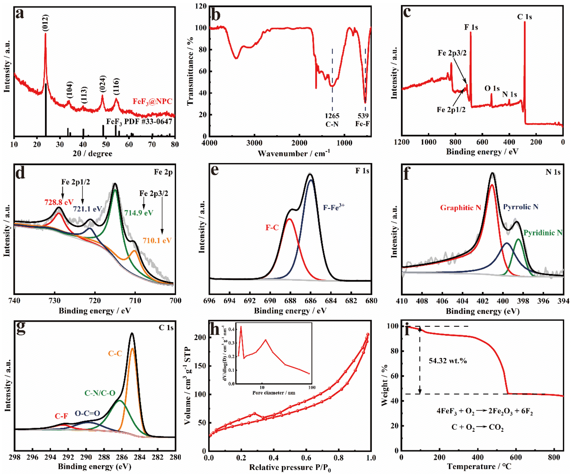 | ||
| Fig. 2 (a) XRD patterns, (b) FTIR spectra, (c) XPS survey spectrum, (d) Fe 2p, (e) F 1s, (f) N 1s and (g) C 1s XPS spectra, (h) N2 sorption isotherm and pore size distribution, and (i) TGA curve in air of FeF3@NPC. | ||
The effects of the mass ratio of PTFE to Fe2O3@SOP and heat treatment temperature on the formation of FeF3@NPC were explored. As the mass ratio of PTFE/Fe2O3@SOP decreases from 6![[thin space (1/6-em)]](https://www.rsc.org/images/entities/char_2009.gif) :1 to 3:1, the interconnected spheroidal morphology remains unchanged (Fig. 3a/b), but Si in the SOP cannot be completely etched, which can be shown by EDS analysis (Fig. 3c). On increasing the mass ratio of PTFE/Fe2O3@SOP to 10:1, the interconnected spheroidal shape collapses and the carbon content increases (Fig. 3d–f), implying a decrease of the active substance FeF3. Thus, PTFE is critical for creating a nanoconfined spheroidal carbon shell and tuning the FeF3 content. Increasing the heating temperature to 800 °C, the spheroidal FeF3@NPC nanoparticles are aggregated into a blocky morphology (Fig. 3g/h), which indicates that a higher heating temperature affects the regular morphology of FeF3@NPC. To further explore the formation of FeF3@NPC, TG and gas emission curves of the PTFE and Fe2O3@SOP mixture were constructed. The TG curve (Fig. S4†) shows that PTFE and Fe2O3@SOP react violently at around 580 °C, which can be attributed to the fluorination of Fe2O3 based on the major gas product (C2F4) of PTFE in the pyrolysis process and the etching of Si in the SOP through the reaction of Si with C2F4 to generate SiF4 (g) (Fig. 3i),24,31 resulting in the formation of FeF3@NPC.
:1 to 3:1, the interconnected spheroidal morphology remains unchanged (Fig. 3a/b), but Si in the SOP cannot be completely etched, which can be shown by EDS analysis (Fig. 3c). On increasing the mass ratio of PTFE/Fe2O3@SOP to 10:1, the interconnected spheroidal shape collapses and the carbon content increases (Fig. 3d–f), implying a decrease of the active substance FeF3. Thus, PTFE is critical for creating a nanoconfined spheroidal carbon shell and tuning the FeF3 content. Increasing the heating temperature to 800 °C, the spheroidal FeF3@NPC nanoparticles are aggregated into a blocky morphology (Fig. 3g/h), which indicates that a higher heating temperature affects the regular morphology of FeF3@NPC. To further explore the formation of FeF3@NPC, TG and gas emission curves of the PTFE and Fe2O3@SOP mixture were constructed. The TG curve (Fig. S4†) shows that PTFE and Fe2O3@SOP react violently at around 580 °C, which can be attributed to the fluorination of Fe2O3 based on the major gas product (C2F4) of PTFE in the pyrolysis process and the etching of Si in the SOP through the reaction of Si with C2F4 to generate SiF4 (g) (Fig. 3i),24,31 resulting in the formation of FeF3@NPC.
 | ||
| Fig. 3 (a) SEM image, (b) TEM image, and (c) EDX spectrum of the product obtained by the mass ratio of PTFE/Fe2O3@SOP = 3:1. (d) SEM image, (e) TEM image, and (f) EDX spectrum of the product obtained by the mass ratio of PTFE/Fe2O3@SOP = 10:1. (g) SEM image, and (h) TEM image of the product obtained under 800 °C. (i) Gas emission curves of PTFE and Fe2O3@SOP mixture during the pyrolysis process. | ||
The successful synthesis of FeF3@NPC has inspired us to explore the possibility of utilizing the in situ reaction approach in the preparation of other N-doped porous carbon-confined metal fluorides. Indeed, as seen in the SEM images and XRD patterns shown in Fig. 4, CoF2@NPC, CuF2@NPC, and AlF3@NPC can be easily synthesized using common metal oxides such as Co3O4, Cu2O and Al2O3, respectively, which can be further supported by the EDS spectra of CoF2@NPC, CuF2@NPC, and AlF3@NPC (Fig. S5–7†).
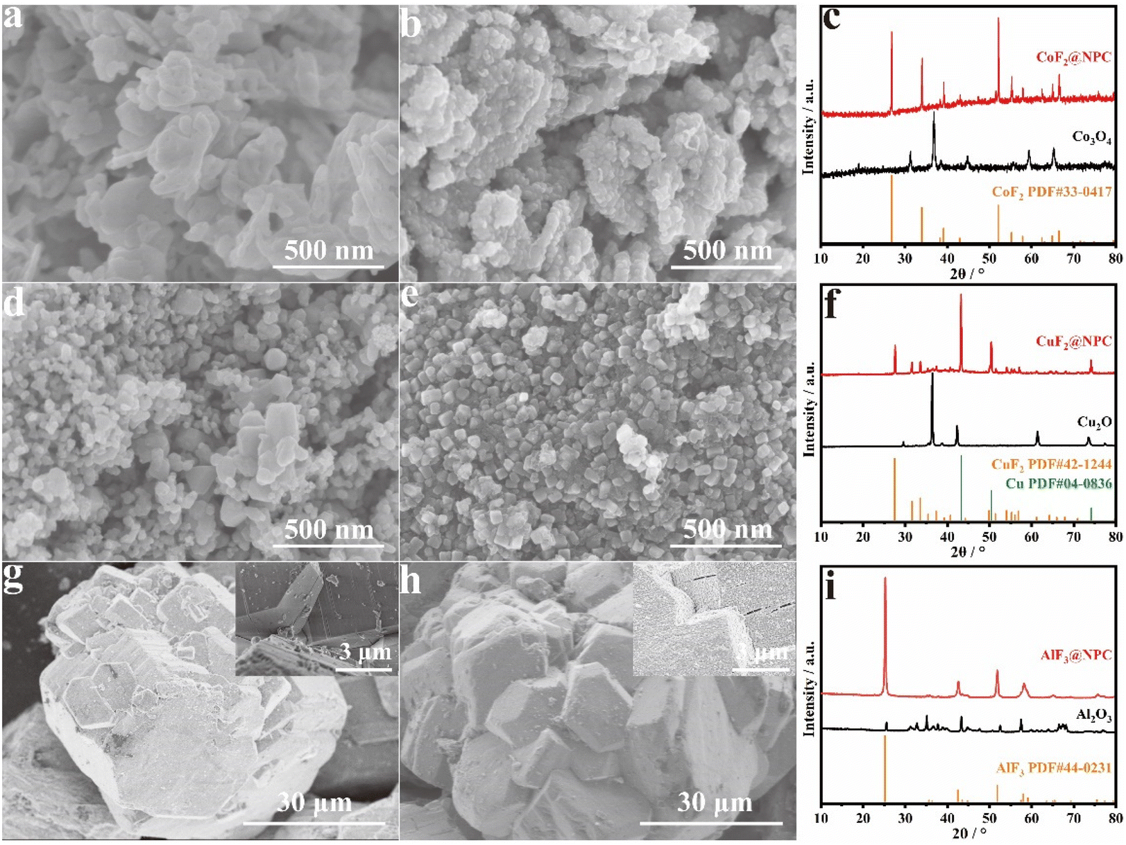 | ||
| Fig. 4 (a) SEM image of Co3O4, (b) SEM image, and (c) XRD patterns of CoF2@NPC. (d) SEM image of Cu2O, (e) SEM image, and (f) XRD patterns of CuF2@NPC. (g) SEM image of Al2O3. (h) SEM image and (i) XRD patterns of AlF3@NPC. | ||
To systematically assess the electrochemical properties of FeF3@NPC, FeF3@NPC/Li cells with an FeF3@NPC cathode were constructed. The CV profiles of the FeF3@NPC cathode in the initial cathodic sweep show a pair of cathodic/anodic peaks at 2.93/3.15 V (Fig. 5a), which correspond to lithiation/delithiation of the FeF3 crystal structure, respectively.32,33 An additional pair of cathodic/anodic peaks at 3.28/3.40 V is exhibited, relating to the redox reactions of Li+ with FeF3 to form the Li0.5FeF3 intermediate.34 The cathodic/anodic peaks are almost overlapped during the subsequent cycles, implying excellent electrochemical stability of FeF3@NPC. The cycling performance of FeF3@NPC and commercial FeF3 cathodes is presented in Fig. 5b. The FeF3@NPC cathode delivers excellent specific capacities of 249 and 203 mA h g−1 at 0.2 C over 1 and 100 cycles, respectively. In contrast, the commercial FeF3 cathode suffers significant capacity decay, and only maintains a low capacity of 29 mA h g−1 over 100 cycles, attributable to poor mechanical and interfacial stability. In addition, the specific capacity of the NPC cathode is only 16 mA h g−1 over 100 cycles (Fig. S8†), revealing that the capacity contribution of NPC can be negligible. Compared with reported FeF3 cathode materials, the FeF3@NPC cathode showcases comparable or better electrochemical properties (Table S1†). The rate capability of the FeF3@NPC cathode is presented at different C-rates (Fig. 5c/d). At varying C-rates from 0.2 to 5 C, the FeF3@NPC cathode exhibits high specific capacities of 229, 218, 205, 193, and 181 mA h g−1, respectively. As the current returns to 0.2 C, a high reversible capacity of 221 mA h g−1 can be recovered. In sharp contrast, the commercial FeF3 cathode delivers ultralow capabilities of 63, 44, 27, 18, and 9 mA h g−1, respectively, signifying the outstanding rate capability of FeF3@NPC. This good rate performance proves the improved electrochemical kinetics and rapid electronic/ionic transport characteristics of FeF3@NPC, which can be buttressed by the relatively low charge-transfer resistance (Rct) (Fig. S9†). The long cycle life of the FeF3@NPC cathode was evaluated at 2 C (Fig. 5g). The FeF3@NPC cathode preserves a stable reversible capacity of 172 mA h g−1 over 500 cycles of charge/discharge, corresponding to a superior capacity retention of 86.9% and a low capacity decay of 0.026% cycle−1, accompanied by an almost 100% coulombic efficiency, evidencing the structural advantage of FeF3@NPC.
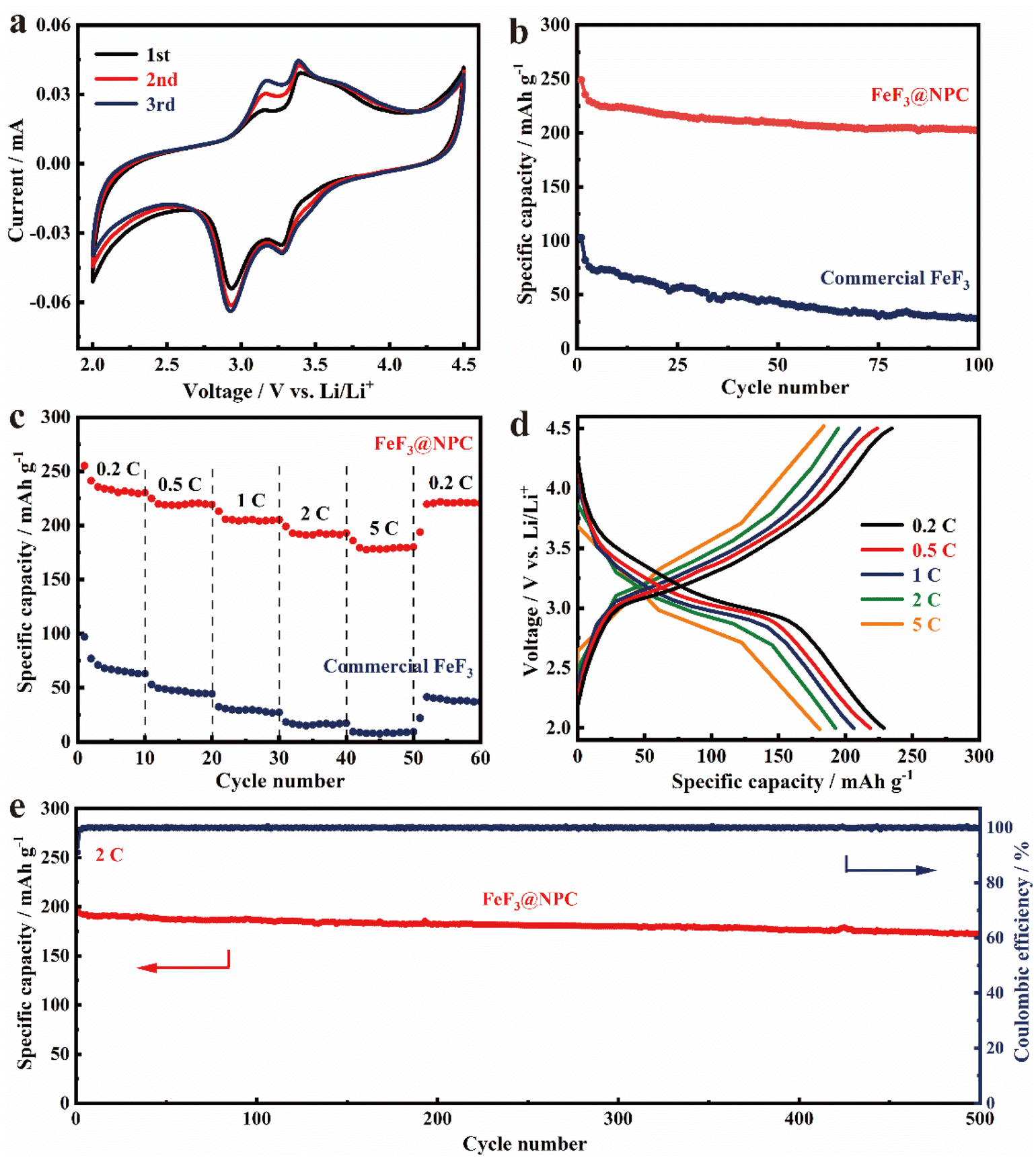 | ||
| Fig. 5 (a) CV curves of FeF3@NPC at 0.2 mV s−1. (b) Cycling performance of FeF3@NPC and commercial FeF3 at 0.2 C. (c) Rate performance of FeF3@NPC and commercial FeF3 at different rates from 0.2 C to 5 C. (d) Voltage profiles of FeF3@NPC at different current densities. (e) Long-term cycling performance of FeF3@NPC at 2 C. | ||
The integrity of the FeF3@NPC cathode after cycling was investigated with the postmortem SEM analysis (Fig. 6a/b and S10†). After the cycling test, the FeF3@NPC cathode well maintains its original morphology without cracks, revealing the structural integrity of the cathode. The elemental analysis and TEM image of the cycled FeF3@NPC cathode (Fig. 6c/d) show that the C, F and Fe elements are still homogeneously distributed in the carbon conduction network, and the N-doped porous carbon shell surrounding the FeF3 nanoparticles remains intact, further indicating good robustness of the cathode and effective prevention of FeF3 dissolution into the electrolyte. Compared to the FeF3@NPC cathode before cycling, the thickness variation of the cycled FeF3@NPC cathode is only 11.2% (Fig. 6e/f), implying that the well-constructed FeF3@NPC nanocomposite can effectively accommodate severe volume fluctuation of FeF3. Thus, the resulting FeF3@NPC/Li batteries present excellent lithium storage performance.
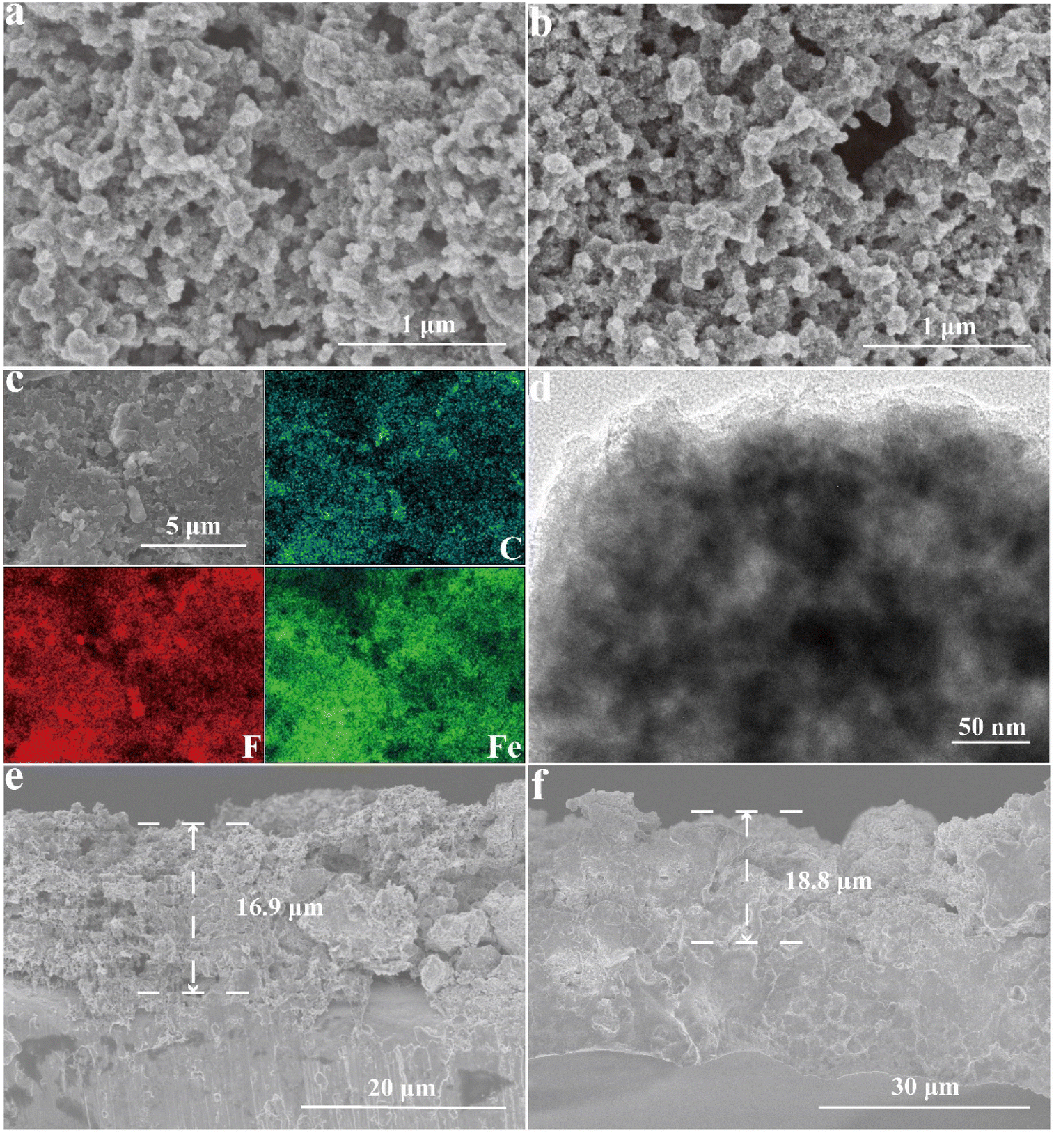 | ||
| Fig. 6 (a and b) SEM images of the FeF3@NPC cathode before and after 100 cycles. (c) EDS elemental mappings, and (d) TEM image of the FeF3@NPC cathode after 100 cycles. (e and f) Cross-sectional SEM images of the FeF3@NPC cathode before and after 100 cycles. | ||
To investigate the electrochemical kinetics of the FeF3@NPC cathode, CV curves at different scanning rates (0.2, 0.3, 0.4, 0.5, 0.6, 0.7, 0.8, and 0.9 mV s−1) are presented in Fig. 7a. All the CV curves maintain the same trend, and the redox current intensity increases with the upswing of scanning rates, demonstrating the reversibility of the electrochemical conversion reaction for the FeF3@NPC cathode.20 Moreover, the slight redox peak shifts imply that the FeF3@NPC cathode possesses fast kinetics. The relationship between the current (i) and the scanning rate (ν) obeys eqn (1) and (2):35
| i = avb | (1) |
| log(i) = blog(v) + log(a) | (2) |
| i(V) = k1v + k2v1/2 | (3) |
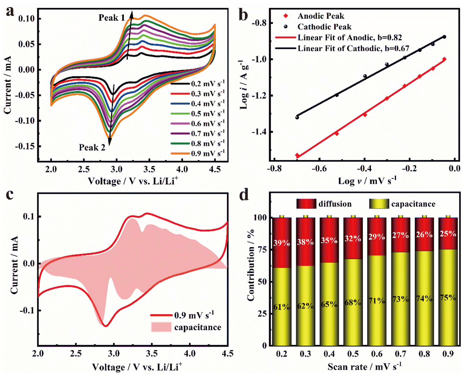 | ||
| Fig. 7 (a) CV curves at different scanning rates; (b) the fitted b values determined by the peak current and scanning rate; (c) schematic diagram of the capacitive contribution at 0.9 mV s−1; and (d) capacity contribution ratio at various scanning rates of FeF3@NPC. | ||
Experimental
Chemicals and materials
Polytetrafluoroethylene (PTFE), Fe2O3 powder, Co3O4 powder, Cu2O powder, Al2O3 powder, glutaraldehyde solution (50% in H2O), 3-aminopropyltriethoxysilane (APTES), commercial FeF3, N-methyl pyrrolidone (NMP), and polyvinylidene fluoride (PVDF) were purchased from Aladdin (China). Acetylene black (AB) was offered from Guangzhou Lithium Force Energy Technology Co. (China), commercial electrolyte using EC/DMC/DEC (v/v/v = 1:1:1) solvent with 1 M LiPF6 was purchased from Shanghai Xiaoyuan Energy Technology Co. (China).
Synthesis of Fe2O3@SOP
APTES (2.66 g, 12.0 mmol) and Fe2O3 (2.87 g, 18.0 mmol) were placed in a 500 mL glass bottle with C2H5OH/H2O (v/v = 60 mL:240 mL) and stirred for 1 h. Then, glutaraldehyde solution (50% in H2O, 2.40 g, 12.0 mmol) was added dropwise and kept under vigorous stirring for 6 h. The precipitate was washed with C2H5OH/H2O and subsequently dried at 80 °C, yielding a Schiff-base organic precursor containing Fe2O3, i.e., Fe2O3@SOP.
Synthesis of FeF3@NPC
0.5 g of Fe2O3@SOP and 3.0 g of PTFE powder were well ground for 0.5 h, and then calcined at 650 °C for 4 h under an Ar atmosphere to obtain FeF3@NPC. Other NPC-confined metal fluorides were synthesized via the same procedures with different metallic oxides.Material characterization
The surface morphology, elemental mapping, and microstructure characterization were analyzed using a transmission electron microscope (TEM, Hitachi S-4800) and a scanning electron microscope (SEM, Hitachi S-4800). The chemical states were collected using an X-ray photoelectron spectrometer (XPS, ESCALAB250). The conductivity was measured using a four-point probe instrument (RTS-9). FTIR spectra were recorded using a Nicolet iS50. The crystal structures were obtained using an X-ray diffractometer (XRD, X'Pert Pro MPD) and a Raman spectrometer (HORIBA Jobin Yvon). The N2 adsorption isotherm and pore-size distribution were tested on an SI-MP-10. Pyrolysis characteristics were analysed on a TG-MS analyzer (STA449 F3). Thermogravimetric analysis (TGA) was performed using a PCPFEIFFER VACUUMTGA-7 analyzer.Electrochemical measurement
To prepare the electrode, a mixture of 80 wt% FeF3@NPC or commercial FeF3, 10 wt% acetylene black (AB) conductive agent, and 10 wt% polyvinylidene fluoride (PVDF) binder in N-methyl pyrrolidone (NMP) was cast on aluminum foil and dried at 90 °C for 12 h. The FeF3 mass loading was approximately 1.2–1.6 mg cm−2. A 2025-type coin cell assembly was conducted inside an Ar-filled glovebox (Mikrouna) by using FeF3@NPC or commercial FeF3 as the cathode, lithium sheet as the anode, polypropylene membrane as the separator, and 1 M LiPF6/EC:DMC:DEC (v/v/v = 1:1:1) as the electrolyte. Cyclic voltammetry (CV) measurements (0.2 mV s−1, 2.0–4.5 V) and electrochemical impedance spectroscopy (EIS) measurements (0.01 Hz to 0.1 MHz) were recorded using a Zahner IM6 electrochemical workstation. The galvanostatic discharge/charge tests were conducted using a Neware multichannel battery system. The electrochemical capacities of the electrodes were based on the mass of FeF3.
Conclusions
In summary, an innovative in situ synthetic approach is proposed to make N-doped porous carbon-confined metal fluorides. The afforded FeF3@NPC with a confined N-doped carbon-coated space can facilitate fast Li+/e− diffusion kinetics, buffer severe volume fluctuation and prevent the active substance FeF3 from interacting with the electrolyte, thus enabling a high capacity utilization of 249 mA h g−1 at 0.2 C, together with remarkable C-rate capability and excellent cycle life. This work opens up an efficient pathway for developing nanoconfined metal fluoride-based materials to improve lithium batteries.Author contributions
Jinlong Hu: conceptualization, methodology, investigation, formal analysis, writing – original draft, and writing – review & editing. Weijun Xu: resources and software. Lingzhi Zhang: supervision and writing – review & editing.Data availability
The data supporting this article have been included as part of the ESI.†The data that support the findings of this study are available from the corresponding author upon reasonable request.
Conflicts of interest
There are no conflicts to declare.Acknowledgements
This study was supported by the Key-Area Research and Development Program of Guangdong Province under Grant (2023B0909060004) and Dongguan Municipal Key R&D Program (20221200300112).References
- F. Wu, J. Maier and Y. Yu, Chem. Soc. Rev., 2020, 49, 1569–1614 RSC.
- F. X. Wu, V. Srot, S. Q. Chen, M. Y. Zhang, P. A. Aken, Y. Wang, J. Maier and Y. Yu, ACS Nano, 2021, 15, 1509–1518 CrossRef PubMed.
- S. S. Xiao, P. T. Sun, Y. Y. Xie, X. G. Zhou, Y. Li and L. Y. Wang, J. Mater. Chem. A, 2024, 12, 20783–20802 RSC.
- E. Zhao, O. Borodin, X. S. Gao, D. Lei, Y. R. Xiao, X. L. Ren, W. B. Fu, A. Magasinski, K. Turcheniuk and G. Yushin, Adv. Energy Mater., 2018, 8, 1800721 CrossRef.
- X. J. Xu, F. K. Li, D. C. Zhang, S. M. Ji, Y. P. Huo and J. Liu, Mater. Chem. Front., 2022, 6, 3512–3521 RSC.
- W. W. Zhang, B. Song, M. L. Wang, T. T. Miao, X. L. Huang, E. H. Zhang, X. W. Zhan, Y. Yang, H. Zhang and K. Lu, Energy Environ. Sci., 2024, 17, 5273–5282 RSC.
- W. T. Gu, O. Borodin, B. Zdyrko, H. T. Lin, H. Kim, N. Nitta, J. X. Huang, A. Magasinski, Z. Milicev, G. Berdichevsky and G. Yushin, Adv. Funct. Mater., 2016, 26, 1507–1516 CrossRef CAS.
- L. P. Li, J. H. Zhu, M. W. Xu, J. Jiang and C. M. Li, ACS Appl. Mater. Interfaces, 2017, 9, 17992–18000 CrossRef CAS.
- C. L. Li, L. Gu, J. W. Tong, S. Tsukimoto and J. Maier, Adv. Funct. Mater., 2011, 21, 1391–1397 CrossRef CAS.
- Y. S. Shi, X. Z. Xu, J. Li, J. Y. Li, P. P. Yin, Q. T. Jiang, J. J. Wang, W. B. Li, K. H. Xu, K. Zhang, J. Yang and X. F. Li, ACS Appl. Mater. Interfaces, 2023, 15, 41504–41515 CrossRef CAS PubMed.
- Y. J. Wang, P. Zhou, M. Y. Zhang, Z. J. He, Y. Cheng, Y. Zhou and F. X. Wu, Energy Storage Mater., 2023, 60, 102847 CrossRef.
- H. Jung, J. Shin, C. Chae, J. K. Lee and J. Kim, J. Phys. Chem. C, 2013, 117, 14939–14946 CrossRef CAS.
- F. Badway, N. Pereira, F. Cosandey and G. G. Amatucci, J. Electrochem. Soc., 2003, 150, 1209–1218 CrossRef.
- J. Ding, X. Y. Zhou, C. C. Luo, H. R. Xu, J. Yang and J. J. Tang, J. Mater. Sci., 2022, 57, 1261–1270 CrossRef CAS.
- T. Kim, W. J. Jae, H. Kim, M. Park, J. M. Han and J. Kim, J. Mater. Chem. A, 2016, 4, 14857–14864 RSC.
- L. Sun, Y. Li and W. Feng, Small Methods, 2023, 7, 2201152 CrossRef.
- W. T. Gu, A. Magasinski, B. Zdyrko and G. Yushin, Adv. Energy Mater., 2015, 5, 1401148 Search PubMed.
- Y. S. Shi, P. P. Yin, J. Li, X. Z. Xu, Q. T. Jiang, J. Y. Li, H. M. K. Sari, J. J. Wang, W. B. Li, J. H. Hu, Q. X. Lin, J. Q. Liu, J. Yang and X. F. Li, Nano Energy, 2023, 108, 108181 CrossRef.
- Q. Zhang, X. Wu, S. Gong, L. S. Fan and N. Q. Zhang, ChemistrySelect, 2019, 4, 10334–10339 CrossRef.
- Q. X. Cheng, Y. Y. Pan, Y. Y. Chen, A. Zeb, X. M. Lin, Z. Z. Yuan and J. C. Liu, Inorg. Chem., 2020, 59, 12700–12710 CrossRef PubMed.
- J. L. Hu and L. Z. Zhang, J. Mater. Chem. A, 2021, 9, 27560 RSC.
- J. Li, L. Fu, J. Zhu, W. Yang, D. Li and L. Zhou, ChemElectroChem, 2019, 6, 5203–5210 CrossRef.
- H. Wang, B. Hou, Y. Yang, Q. Chen, M. Zhu, A. Thomas and Y. Liao, Small, 2018, 14, 1803232 CrossRef PubMed.
- K. Du, R. Tao, C. Guo, H. F. Li, X. L. Liu, P. M. Guo, D. Y. Wang, J. Y. Liang, J. L. Li, S. Dai and X. G. Sun, Nano Energy, 2022, 103, 107862 CrossRef CAS.
- H. Jung, J. Shin, C. Chae, J. K. Lee and J. Kim, J. Phys. Chem. C, 2013, 117, 14939–14946 CrossRef.
- J. Yang, Z. Xu, H. Zhou, J. Tang, H. Sun, J. Ding and X. Zhou, J. Power Sources, 2017, 363, 244–250 CrossRef.
- X. Zhou, H. Sun, H. Zhou, Z. Xu and J. Yang, J. Alloys Compd., 2017, 723, 317–326 CrossRef.
- X. Li, Y. Zhang, Y. Meng, G. Tan, J. Ou, Y. Wang, Q. Zhao, H. Yuan and D. Xiao, ChemElectroChem, 2017, 4, 1856–1862 CrossRef.
- W. Fu, E. Zhao, Z. Sun, X. Ren, A. Magasinski and G. Yushin, Adv. Funct. Mater., 2018, 28, 1801711 CrossRef.
- H. Zhang, M. L. Wang, B. Song, X. L. Huang, W. L. Zhang, E. H. Zhang, Y. W. Cheng and K. Lu, Angew. Chem., Int. Ed., 2024, 63, e202402274 CrossRef PubMed.
- Z. X. Pei, H. F. Li, Y. Huang, Q. Xue, Y. Huang, Z. F. Wang and C. Y. Zhi, Energy Environ. Sci., 2017, 10, 742–749 RSC.
- Y. Q. Shen, X. Y. Wang, H. Hu, M. L. Jiang, X. K. Yang and H. B. Shu, J. Power Sources, 2015, 283, 204–210 CrossRef.
- X. Fan, Y. Zhu, C. Luo, L. Suo, Y. Lin, T. Gao, K. Xu and C. Wang, ACS Nano, 2016, 10, 5567–5577 CrossRef.
- J. Li, L. C. Fu, Z. W. Xu, J. J. Zhu, W. L. Yang, D. Li and L. P. Zhou, Electrochim. Acta, 2018, 281, 88–98 CrossRef.
- Z. Jiang, Y. J. Wang, X. F. Chen, F. L. Chu, X. S. Jiang, F. Kwofie, Q. Pei, S. Luo, J. Arbiol and F. X. Wu, J. Mater. Chem. A, 2023, 11, 21541–21552 RSC.
- X. Hua, A. S. Eggeman, E. Castillo-Martínez, R. Robert, H. S. Geddes, Z. Lu, C. J. Pickard, W. Meng, K. M. Wiaderek, N. Pereira, G. G. Amatucci, P. A. Midgley, K. W. Chapman, U. Steiner, A. L. Goodwin and C. P. Grey, Nat. Mater., 2021, 20, 841–850 CrossRef PubMed.
Footnotes |
| † Electronic supplementary information (ESI) available: SEM images, EDS, XRD, Raman, TGA and tables of calculation results. See DOI: https://doi.org/10.1039/d4gc04097j |
| ‡ These authors contributed equally to this work. |
| This journal is © The Royal Society of Chemistry 2024 |