 Open Access Article
Trace xenon detection in ambient helium by double-pulse laser-induced breakdown spectroscopy
L.
Garrett
 *ab,
M.
Burger
 ab,
Y.
Lee
cd,
H.
Kim
e,
P.
Sabharwall
f,
S.
Choi
 e and
I.
Jovanovic
ab
aDepartment of Nuclear Engineering and Radiological Sciences, University of Michigan, Ann Arbor, MI 48109, USA. E-mail: lgarr@umich.edu
bGérard Mourou Center for Ultrafast Optical Science, University of Michigan, Ann Arbor, MI 48109, USA
cDepartment of Nuclear and Quantum Engineering, Korea Advanced Institute of Science and Technology, Daejeon 34141, Republic of Korea
dDevice Solutions, Samsung Electronics, Pyeongtaek 17786, Republic of Korea
eDepartment of Nuclear Engineering, Seoul National University, Seoul 08826, Republic of Korea
fIdaho National Laboratory, Idaho Falls, ID 83415, USA
First published on 12th November 2024
Abstract
Safe operation of next-generation nuclear reactors is contingent on developing and effectively operating new diagnostics methods. For helium-cooled fast reactors, one important safety concern is the onset of fuel-cladding failure, which could be detected from the increased concentration of mobile fission fragments such as xenon in the helium coolant. In a previous study [Burger et al., JAAS, 2021, 36, 824], we demonstrated that laser-induced breakdown spectroscopy (LIBS) is a viable candidate for sensitive xenon detection in helium, offering a limit of detection on the order of 0.2 μmol mol−1 for 104 laser shots. Here, we demonstrate that double-pulse LIBS enhances the xenon signal by approximately 14× at a concentration of 1 μmol mol−1 in an ambient helium environment, which results in significantly improved sensitivity. Additionally, we examine the effect of relative energy in two laser pulses, interpulse delay, and laser polarization on the xenon signal enhancement. These results further motivate the development of LIBS sensors for this application.
1 Introduction
Laser-induced breakdown spectroscopy (LIBS) has been proposed as a diagnostic technique for use in advanced nuclear reactor systems1–10 thanks largely to the ability to remotely detect a wide range of materials across all states of matter and the rapid analysis it enables.11,12 One potential use case for LIBS is in the coolant stream of generation IV gas-cooled fast reactors (GCFRs) to monitor the presence of short-lived fission products such as certain isotopes of Xe and Kr.3,5,13 Significant increases in the concentration of these products within the coolant stream could serve as an early indication of micro-crack formation within the fuel cladding. If left unchecked, the resultant leaks can increase the radioactivity of the coolant stream, and the released Xe atoms can act as a reactor poison.13,14In LIBS, a high-power laser pulse ionizes the analyte of interest and produces a microplasma that emits material-specific light upon de-excitation. While LIBS offers the benefit of near in situ measurements, its sensitivity is lower than that achieved by many other commonly used chemical assay techniques such as gas chromatography and mass spectroscopy, which regularly report ppb limits of detection.15,16 Such concentrations are more representative of the impurity contamination level that would exist during standard operation.17 Therefore, diagnostic equipment that monitors the composition of the reactor coolant for the presence of impurities would greatly benefit from increased sensitivity.
In a previous study, we demonstrated the feasibility of using LIBS for monitoring reactors that use He as the primary coolant, reporting a 0.2 μmol mol−1 Xe limit of detection (LOD) for 104 laser shots.3 To improve sensitivity in detecting He, here we apply double-pulse (DP) LIBS, which is a well-established technique that can enhance the traditional single-pulse (SP) LIBS analytical signal. Several reviews of DP-LIBS already exist, including ref. 18–20, and thus only a brief overview is presented here. In DP-LIBS, a second laser pulse is introduced following the initial breakdown-inducing pulse after an interpulse delay (IPD) that typically ranges from picoseconds to microseconds. The second pulse reheats the plasma and increases the emission intensity.18 It has been shown that the use of DP-LIBS can improve signal intensity by as much as two orders of magnitude when compared to SP LIBS.21,22 The mechanism behind the enhancement has been attributed to several factors including but not limited to increased plasma temperature,23,24 longer emission lifetimes,23,25 higher breakdown efficiency,26,27 and rarefaction of the gas environment surrounding the generated plasma.28 Currently, there is no consensus that one of these effects is most important for signal enhancement, as different effects have been shown to be prominent in experiments employing different chemical species and environmental conditions.20 The combination of these effects has also been attributed to lower self-absorption coefficients.29
The majority of these prior findings relate to measurements of solid samples; few studies have examined the use of DP-LIBS on gaseous analytes. In contrast to the advantages of DP-LIBS with solid samples, early studies of gaseous carbon-based analytes30,31 noted negligible signal enhancement in DP-LIBS and, at times, even reduced signal intensity. This discrepancy may be the result of adverse effects not considered in those studies, including species reactivity and self-absorption as well as an incomplete optimization over the available parameter space that includes recording parameters, IPD, laser configuration, relative energy of two laser pulses, and laser wavelength, among others.18
Here, we demonstrate that for constrained energy delivered to the target, DP-LIBS can improve the signal intensity by a factor of two for atomic spectral lines and by an order of magnitude for ionic spectral lines compared to SP LIBS in experiments with trace Xe detection in He ambient. We estimate a new limit of detection on the order of 20 ppb for 104 laser shots and demonstrate that enhancement provided by DP-LIBS is most significant at lower Xe concentrations. This helps to further motivate the use of LIBS in nuclear reactor monitoring, where ppb level sensitivities are required.17 We present a scheme for signal optimization that seeks to efficiently navigate the large parameter space associated with DP-LIBS. Finally, we show that further improvement of sensitivity is possible by the use of circularly polarized beams.
2 Experiment and method
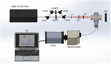
Fig. 1 depicts a schematic of the experimental setup. A 1064 nm, Nd:YAG double-pulse laser (Evergreen, Quantel) operated at a repetition rate of 10 Hz was used. Each beam had a pulse duration of 11 ns and a maximum energy of 300 mJ per pulse. Taking advantage of the cross-polarized beams, pulse energy was controlled using a combination of Brewster angle thin-film polarizers (420-0258E, Eksma Optics) and half-wave plates (WPH05M-1064, Thorlabs) in the configuration shown in Fig. 1 to split, independently attenuate, and recombine the beams. This allowed for the energy to be adjusted without altering the laser gain, pulse duration, and focusing conditions. Beams were recombined after the final thin-film polarizer (denoted TFP4 in Fig. 1) to set up a collinear DP scheme. The beams were focused using a 100 mm focal length lens. To overcome the high ionization energy of the ambient He, a Galilean telescope was placed prior to the focusing lens to modify the beam waist, providing a 5× beam expansion and a maximum focused laser irradiance on the order of 1012 W cm−2. The timing was maintained using a digital delay generator (DG645, Stanford Research Systems), and the interpulse delay was optically measured using a 1 GHz bandwidth photodiode (DET210, Thorlabs) and a 100 MHz bandwidth oscilloscope (DSO5014A, Agilent Technologies). The experimental cell was evacuated to the pressure of 4.6 × 10⁻⁴ Pa before introducing certified gas mixtures in He with 99.999% purity of each constituent (Global Rare Gasses) into the cell. All experiments were conducted at atmospheric pressure (1.00 bar) and room temperature (∼20 °C). Spectra were recorded using an intensified CCD (PIMAX-4, Princeton Instruments) cooled to −20 °C coupled to a compact Czerny–Turner spectrogram (MicroHR, 600 lines per mm grating, HORIBA Jobin Yvon) with a 100 μm slit width. The resultant resolution was approximately 1 nm. The light produced by the plasma emission was measured from a 200 mm distance with a collimator (CC52, Andor) and directed to the spectrograph with a 0.4 mm diameter optical fiber bundle. Wavelength calibrations were performed using standard Xe and Ar lamps (Pen Light, Oriel).In the previous study,3 the Xe I spectral line located at 823.16 nm was used for analytical measurements due to its relatively high intensity and the limited contribution of plasma continuum within the near-IR spectral region. This study also examined this line to demonstrate repeatability and establish a reference result in a different experimental setup. Additionally, to compare the enhancement of atomic and ionic Xe emissions, analysis was also performed on the Xe II 441.84 nm emission. The emission wavelength, transition probability, energy levels, and degeneracies of all observed transitions are displayed in Table 1. Due to the limited resolution of the spectrometer in our setup, several ionic emissions in the range of 418–420 nm cannot be resolved.
| Species | Wavelength (nm) | Einstein coeff. (106 s−1) | Lower level | Upper level | ||||||
|---|---|---|---|---|---|---|---|---|---|---|
| (eV) | g i | Config. | Term | (eV) | g j | Config. | Term | |||
| a Of the Xe II lines examined in this study, only the emission at 441.84 nm has published transition probability data. | ||||||||||
| Xe I | 419.30 | 0.22 | 8.31 | 5 |

|
2[3/2]° | 11.27 | 7 |

|
2[5/2] |
| 820.63 | 20 | 9.44 | 1 |

|
2[1/2]° | 10.95 | 3 |

|
2[3/2] | |
| 823.16 | 28.6 | 8.31 | 5 |

|
2[3/2]° | 9.82 | 5 | 5p5(2P°)6s | 2[3/2] | |
| 826.65 | 16.2 | 9.56 | 3 |

|
2[1/2]° | 11.06 | 3 |

|
2[1/2] | |
| 828.01 | 36.9 | 8.43 | 3 |

|
2[3/2]° | 9.93 | 1 |

|
2[1/2] | |
| 834.68 | 42 | 9.56 | 3 |

|
2[1/2]° | 11.05 | 5 |

|
2[3/2] | |
| 840.20 | 3.06 | 8.31 | 5 |

|
2[3/2]° | 8.78 | 3 |

|
2[3/2] | |
| Xe II | 417.99 | 10a | 16.07 | 4 | 5s25p4(1D2)6d | 2[1]° | 19.09 | 4 | 5s25p4(1D2)6d | 2[1] |
| 418.00 | 13.86 | 4 | 5s25p4(3P2)6p | 2[2]° | 19.09 | 4 | 5s25p4(3P2)6d | 2[2] | ||
| 419.31 | 15.97 | 6 | 5s25p4(1D2)6p | 2[3]° | 18.93 | 8 | 5s25p4(1D2)6d | 2[4] | ||
| 420.84 | 13.86 | 4 | 5s25p4(3P2)6p | 2[2]° | 16.80 | 6 | 5s25p4(3P2)6d | 2[2] | ||
| 421.37 | 14.92 | 2 | 5s25p4(3P0)6p | 2[1]° | 17.87 | 4 | 5s25p4(3P0)6d | 2[2] | ||
| 423.82 | 13.88 | 6 | 5s25p4(3P2)6p | 2[2]° | 16.80 | 6 | 5s25p4(3P2)6d | 2[2] | ||
| 429.64 | 13.86 | 4 | 5s25p4(3P2)6p | 2[2]° | 16.74 | 2 | 5s25p4(1D2)5d | 2[0] | ||
| 441.84 | 13.58 | 6 | 5s25p4(1D2)6s | 2[2] | 16.39 | 6 | 5s25p4(1D2)6p | 2[2]° | ||
| 444.81 | 15.26 | 6 | 5s25p4(3P1)6p | 2[2]° | 18.05 | 8 | 5s25p4(3P1)6d | 2[3] | ||
| 446.21 | 14.09 | 8 | 5s25p4(3P2)6p | 2[3]° | 16.87 | 10 | 5s25p4(3P2)6d | 2[4] | ||
Signal improvement can be quantified in terms of enhancement and signal-to-noise ratio (SNR). In this study, enhancement is defined as the ratio of the spectral line area in DP measurement to that of the SP measurement conducted at the maximum pulse energy of 300 mJ. SNR is defined as
SNR = ![[X with combining macron]](https://www.rsc.org/images/entities/i_char_0058_0304.gif) /σB, /σB, | (1) |
![[X with combining macron]](https://www.rsc.org/images/entities/i_char_0058_0304.gif) is the peak area and σB is the standard deviation of the background. To calculate the peak area, each measurement frame is fit to a Voigt distribution such that
is the peak area and σB is the standard deviation of the background. To calculate the peak area, each measurement frame is fit to a Voigt distribution such that | (2) |
 . A Levenberg–Marquardt nonlinear least-squares regression is performed; if no minimum of the residuals is found at this point, that spectral frame is rejected for not reaching convergence. Because the Voigt profile is a convolution of two normalized profiles, the spectral peak area is equal to the amplitude term, I0. The noise term is calculated as the standard deviation of all vertical offset terms divided by the square root of the number of laser shots within the measurement set. Due to possible interference from the nitrogen molecular band beginning at ∼820.5 nm,33 line symmetry is assumed such that fits of the Xe I 823.16 nm can be biased towards the longer-wavelength part of the spectral line and exclude the shorter-wavelength part that may be affected by interference. In cases where the limited resolution acts to blend spectral lines such as for the Xe II emissions between 418 nm and 420 nm, if all emissions could be attributed to the same ionization level (i.e., atomic Xe or ionic Xe), numerical integration was used over the span of blended features.
3 Results and discussion
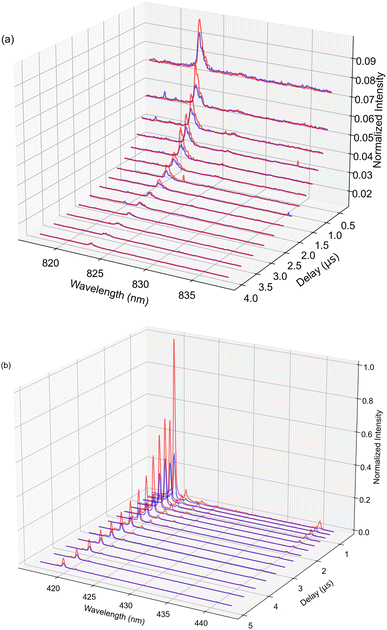
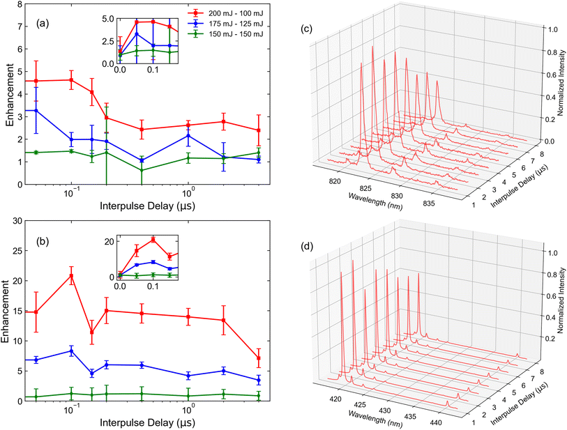
The known transience of the LIBS plasma merits a careful investigation of its temporal behavior. Fig. 2 displays visualizations of the temporally resolved spectral data for the 1% Xe in He gas mixture. To improve measurement statistics at later observation times when the plasma is cooler, the ICCD gate width is gradually increased with increasing ICCD delay. DP measurements were conducted at an interpulse delay of 150 ns and a pulse energy combination of 175 mJ and 125 mJ for initial measurements. For both spectral regions, the emission is brightest over the first microsecond of the plasma lifetime. However, due to the strong continuum during this period, avoiding early points in the lifetime improves the SNR of characteristic spectral lines. The optimization of ICCD light collection parameters is discussed in more detail below. Immediately, the increased intensity of ionic emissions relative to the atomic emissions, particularly when the second pulse is introduced, can be observed. This is a central advantage of analysis with the ionic lines. However, the increased number of lines in the 420 nm region prevents lines from being uniquely resolved. This would present a challenge in the use case where other elements would be present in the analyte, complicating the spectrum.Several studies have observed that relative pulse energies and IPD in DP LIBS significantly affect the emission intensity of observed spectral features.34,35 To quantify these effects in our experiment, measurements were taken for different pairs of pulse energies such that the total energy delivered to the focal spot did not exceed 300 mJ, as shown in Fig. 3. Each data point corresponds to a DP measurement resulting from the accumulation of 1000 laser shots for 932 ppm (μmol mol−1) Xe in ambient He. Measurements were taken using a gate width of 100 μs and gate delay of 10 μs for the atomic emission, based on optimized spectral collection parameters from our previous study.3 To account for the shorter expected lifetime of the ionic emission, a delay of 2 μs was selected based on Fig. 2, with further optimization of the ICCD collection parameters discussed later. The error bars in Fig. 3 result from shot-to-shot variations as determined by the signal standard deviation. While previous studies on solid samples noted the results are best when the energy of the second (reheating) pulse exceeds the energy of the breakdown pulse,36,37 the threshold for He breakdown was observed at approximately 150 mJ, meaning that measuring such a condition was not feasible in this experiment while keeping the energy delivered to the focal spot constrained to 300 mJ. Results indicate that the best enhancement and highest SNR both occurred at an IPD delay of ∼100 ns for all conditions measured, nearly identical to the trend previously observed in ref. 34 for a similar experimental setup with steel samples. All subsequent DP measurements were conducted using this IPD. When pulses overlap in time (IPD = 0), negligible enhancement is observed. This agrees with expectations, as the intensity should be equivalent to a SP measurement used for normalization. The characteristic timescale for optimal IPD may suggest that an increase in the amount of ionized material and increases in plasma temperature and density are significant contributors to the observed enhancement based on analyses from previous studies with similar results.18,28 After an IPD of 1 μs, the enhancement of the atomic lines plateaus. Similar results were observed in ref. 23 and 38. Within the Xe matrix, a similar (albeit less pronounced) trend was observed for ionic lines as well. The DP plasma exhibits longer persistence than its SP counterpart for ionic lines, as shown in Fig. 2. This may be attributed to the increased plasma temperature more readily exciting these higher-energy features.
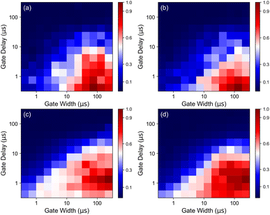
Using the results in Fig. 3, a pulse energy combination of 200 mJ and 100 mJ was selected for subsequent measurements. Fig. 3(c) and (d) display the spectra as a function of IPD for this combination. To determine the optimal point within the plasma lifetime for spectral measurement, a scan of gate width and gate delay of the ICCD was performed for the Xe I 828.01 nm and Xe II 441.84 nm spectral lines. These lines were selected for their respective spectral regions due to their relatively high intensity and ability to be unambiguously resolved under the given measurement conditions. The SNRs measured for each combination of gate width and gate delay for the SP and DP measurement conditions are shown in Fig. 4. Each set of parameters is measured with 1000 laser shots. For atomic measurements, regardless of the pulse modality, the optimal SNR is observed at a delay of 200 ns and gate width of 100 μs. The optimal combination of ICCD recording parameters for ionic lines is observed at the same gate width, but at a delay of 1 μs. These parameters were used for all remaining measurements. While the optimal SNR characteristics for longer delay may seem counterintuitive given the earlier prominence of ionic lines, this result can readily be observed by inspecting the time dependence of continuum emission. Ionic emission occurs in the spectral region where the continuum is most intense. This acts to limit the SNR at early delays. In contrast, at 800 nm and longer wavelengths, the continuum emission is comparatively weak, allowing for line emission to be clearly observed over essentially the entirety of plasma lifetime. In both measurements, the presence of metastable states in the He–Xe mixture likely contributes to a long plasma lifetime for signal to be collected.39,40
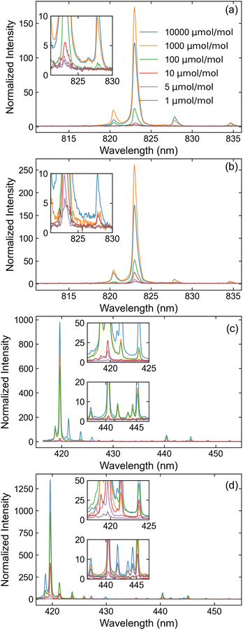
Fig. 5 displays the optimized spectra measured across various Xe concentrations for SP and DP LIBS. Spectra are normalized to their dark count subtracted continuum baselines, such that the signal to background ratio (SBR) can be estimated as SBR = H − 1, where H is the peak height. While signal enhancement is observed in all DP measurements, it is most significant at low concentrations: the atomic spectral lines measured at 1 ppm experienced up to a 4-fold increase in peak intensity while the ionic spectral lines experienced up to a 15-fold increase. In contrast, spectral lines measured at a 1% Xe concentration experienced no perceptible change for either ionization state.
Using the results from Fig. 5, the limit of detection (LOD) is estimated based on calibration curves. The constructed calibration curves for the SP and DP measurements are shown in Fig. 6. Each point on the curve represents the integrated peak area of the spectral feature at the referenced Xe concentration. Similarly to ref. 3, a deviation from linearity is observed at higher concentrations that is likely associated with self-absorption.41 Because of this nonlinearity, linear regressions are performed only on the data measured below 100 ppm, where clear linearity is achieved. Using the data from these regressions, LOD is defined based on the 3σ criterion such that
| LOD = 3σB/k, | (3) |
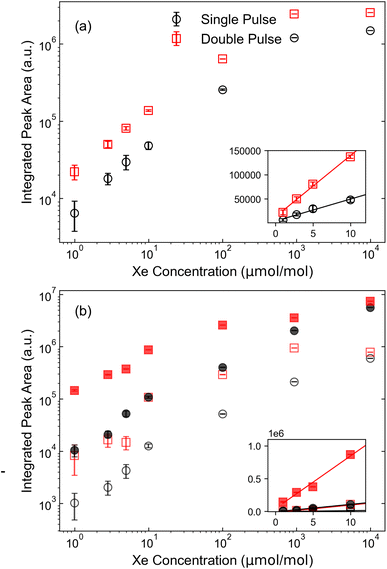 | ||
| Fig. 6 Calibration curves constructed for (a) Xe I 823.16 nm line and (b) Xe II 441.84 nm spectral line (open markers) and Xe II spectral line cluster in the range of 420 nm (closed markers). | ||
| Spectral line | Modality | Limit of detection (ppm) |
|---|---|---|
| Xe I 823.16 nm | SP | 0.32 ± 0.08 |
| DP | 0.15 ± 0.04 | |
| Xe II cluster at 420 nm | SP | 0.17 ± 0.03 |
| DP | 0.02 ± 0.02 | |
| Xe II 441.84 nm | SP | 0.22 ± 0.05 |
| DP | 0.09 ± 0.03 |
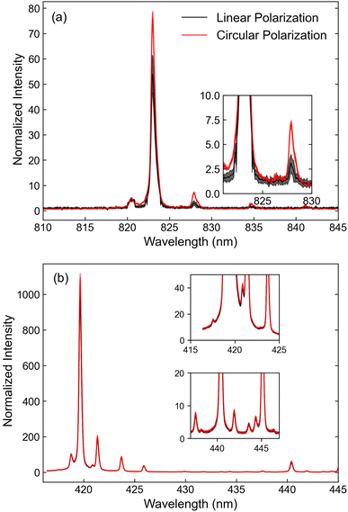
Finally, we examined the effect of laser polarization on signal enhancement. Previous femtosecond LIBS studies reported higher emission intensities with circular laser polarization. This phenomenon has been attributed to faster plasma expansion and improved laser-analyte coupling.42,43 To examine the effects of circular polarization on the Xe emission in nanosecond LIBS, measurements were performed with a quarter-waveplate placed before the expansion telescope and compared to those performed without it; the results are shown in Fig. 7. Line thickness indicates the magnitude of error bars as determined by the standard deviations at each spectral sampling point. Within the region that predominantly contains ionic spectral lines, the effect of circular polarization is statistically insignificant. However, an average enhancement of 1.2 is observed for atomic emissions, suggesting there may be a slight advantage to the use of circularly polarized beams. As with the prior femtosecond measurements, further studies are required to understand the plasma interaction mechanisms sensitive to polarization.
The enhancement of the Xe signal observed with DP-LIBS motivates considering DP-LIBS as a diagnostic for fuel cladding failure monitoring in advanced reactors. However, the determination of LOD using standards of known concentration is still required to evaluate whether DP-LIBS can achieve sufficient sensitivity for day-to-day monitoring of GCFR coolant streams. Additionally, previous studies found that several Xe spectral lines are prone to self-absorption.3,5 Therefore, it is recommended to determine the extent to which this is the case for the spectral lines used in this study and to determine if there are correction factors that may be applied. Future work will also explore time-resolved plasma imaging to examine the plasma morphology throughout its lifetime. The information obtained will also provide the parameters necessary to model the spectra from first principles, which can yield valuable information on the role of self-absorption and other phenomena relevant to the analytical sensitivity of DP-LIBS.44
4 Conclusions
We demonstrated that, for 1 ppm Xe, DP-LIBS offers up to 14× signal enhancement over traditional LIBS in He at atmospheric pressure and room temperature. A LOD between 20–170 ppb is estimated depending on the spectral line used for analysis. We also propose analytical methods to account for possible sources of interference such as closely spaced Xe lines or N impurity features, avoiding the need to use larger spectrographs with better spectral resolution. Furthermore, we show that using circularly polarized beams increases the peak area by a factor of 1.2 for atomic spectral lines. The present study is limited by the range of investigated parameters, and future studies may benefit from more complex configurations that use orthogonal laser pulse incidence or different laser pulse wavelengths and durations. Reliable implementation of LIBS within a GCFR will also require examination of the impact of pressure and temperature, operation in a moving gas stream, and the measurement performance within a chemical matrix that includes other fission fragments.17Data availability
The data that support the findings of this study are available from the corresponding author, L. G., upon reasonable request.Author contributions
The authors confirm their contribution to the paper as follows: study conceptualization and design: I. Jovanovic, M. Burger; data collection: L. Garrett; analysis and interpretation of results: L. Garrett, M. Burger, I. Jovanovic, Y. Lee, S. Choi; draft manuscript preparation: L. Garrett, M. Burger, I. Jovanovic, P. Sabharwall, Y. Lee, H. Kim, S. Choi; oversight and leadership responsibility: I. Jovanovic, M. Burger, P. Sabharwall. All authors reviewed the results and approved the final version of the manuscript.Conflicts of interest
There are no conflicts to declare.Acknowledgements
The submitted document has been created by Battelle Energy Alliance, LLC, Operator of Idaho National Laboratory (INL). INL's work was supported by the U.S. Department of Energy, Office of Nuclear Energy under Contract Number DE-AC07-05ID14517. The work reported in this summary is the result of ongoing efforts supporting the Versatile Test Reactor. This work was also supported by the Department of Defense, Defense Threat Reduction Agency (HDTRA1-20-2-0002). This research was performed under appointment to the Nuclear Nonproliferation International Safeguards Fellowship Program sponsored by the Department of Energy, National Nuclear Security Administration's Office of International Nuclear Safeguards (NA-241).References
- A. Williams and S. Phongikaroon, Appl. Spectrosc., 2018, 72, 1029–1039 CrossRef CAS PubMed.
- Y. Lee, J. Amphlett, H. Ju and S. Choi, Spectrochim. Acta, Part B, 2019, 159, 105649 CrossRef CAS.
- M. Burger, L. Garrett, A. J. Burak, V. Petrov, A. Manera, P. Sabharwall, X. Sun and I. Jovanovic, J. Anal. At. Spectrom., 2021, 36, 824–828 RSC.
- H. B. Andrews and K. G. Myhre, Appl. Spectrosc., 2022, 76, 877–886 CrossRef CAS PubMed.
- H. B. Andrews, J. McFarlane and K. G. Myhre, Appl. Spectrosc., 2022, 76, 988–997 CrossRef CAS PubMed.
- Y. Lee, S. Yoon, N. Kim, W. Yang, M. Burger, I. Jovanovic and S. Choi, Nucl. Eng. Technol., 2022, 54, 4431–4440 CrossRef CAS.
- L. Garrett, B. Morgan, M. Burger, Y. Lee, H. Kim, P. Sabharwall, S. Choi and I. Jovanovic, Sensors, 2023, 23(2), 691–707 CrossRef CAS PubMed.
- Y. Lee, R. Foster, H. Kim and S. Choi, Anal. Chim. Acta, 2023, 1241, 340804 CrossRef CAS PubMed.
- M. Burger, L. Finney, L. Garrett, S. Harilal, K. Hartig, J. Nees, P. Skrodzki, X. Xiao and I. Jovanovic, Spectrochim. Acta, Part B, 2021, 179, 106095 CrossRef CAS.
- Y. Lee, R. Foster, H. Kim, L. Garrett, B. Morgan, M. Burger, I. Jovanovic and S. Choi, Anal. Chem., 2024, 11255–11262 CrossRef CAS.
- D. W. Hahn and N. Omenetto, Appl. Spectrosc., 2012, 64, 335A–366A CrossRef PubMed.
- D. A. Cremers and L. J. Radziemski, Handbook of Laser-Induced Breakdown Spectroscopy, Wiley, New York, 2nd edn, 2013 Search PubMed.
- K. Korsah, P. Ramuhalli, R. Vlim, R. Kisner, C. Britton, D. Wootan, N. Anheier, A. Diaz, E. Hirt, H. Chien, S. Sheen, S. Bakhtiari, S. Gopalsami, A. Heifetz, S. W. Tam, Y. Park, B. Upadhyaya and A. Stanford, Assessment of Sensor Technologies for Advanced Reactors, 2016 Search PubMed.
- C. Azevedo, Eng. Failure Anal., 2011, 18, 1943–1962 CrossRef CAS.
- Modern Practice of Gas Chromatography, ed. R. L. Grob and E. F. Barry, Wiley-Interscience, New Jersey, 4th edn, 2004 Search PubMed.
- C. Dass, Fundamentals of Contemporary Mass Spectrometry, Wiley-Intersience, New Jersey, 2007 Search PubMed.
- P. Sabharwall, K. Weaver, C. Ellis, C. Hangbok, K. Shapalov, R. Schleider, N. Anand, D. Orea, B. H. Choi, T. Nguyen, R. Chavez, N. Sutton, R. Vaghetto, Y. Hassan, X. Sun, I. Jovanovic, A. Manera, V. Petrov, M. Burger, A. Burak, B. Fronk, G. Gaudin, J. Gess, R. Christensen, J. Young, D. Chen and W. Chu, Versatile Test Reactor – Gas Fast Reactor Integrated Report, Idaho National Laboratory Technical Report Limited Distribution, INL/LTD-20-58965, 2020 Search PubMed.
- V. Babushok, F. DeLucia Jr, J. Gottfried, C. Munson and A. Miziolek, Spectrochim. Acta, Part B, 2006, 61, 999–1014 CrossRef.
- J. Scaffidi, S. M. Angel and D. A. Cremers, J. Anal. Chem., 2006, 78, 24–32 Search PubMed.
- Y. Li, D. Tian, G. Yang, K. Liu, C. Wang and X. Han, Appl. Spectrosc. Rev., 2018, 53, 1–35 CrossRef.
- C. Gautier, P. Fichet, D. Menut, J. Lacour, D. L'Hermite and J. Dubessy, Spectrochim. Acta, Part B, 2005, 60, 265–276 CrossRef.
- D. Killinger, S. Allen, R. Waterbury, C. Stefano and E. Dottery, Opt. Express, 2007, 15, 12905–12915 CrossRef CAS PubMed.
- L. St-Onge, V. Detalle and M. Sabsabi, Spectrochim. Acta, Part B, 2002, 57, 121–135 CrossRef.
- I. Elnasharty, F. Doucet, J. Gavel, P. Bouchard and M. Sabsabi, J. Anal. At. Spectrom., 2014, 29, 1660–1666 RSC.
- M. Cui, Y. Deguchi, Z. Wang, Y. Fuijita, R. Liu, F. Shiou and S. Zhao, Spectrochim. Acta, Part B, 2018, 142, 14–22 CrossRef CAS.
- D. Sun, M. Su, C. Dong and G. Wen, Plasma Sci. Technol., 2014, 16, 374–379 CrossRef CAS.
- G. Nicolodelli, G. S. Senesi, I. L. de Oliveira Perazzoli, B. S. Marangoni, V. De Melo Benites and D. M. B. P. Milori, Sci. Total Environ., 2016, 565, 1116–1123 CrossRef CAS PubMed.
- X. Mao, X. Zeng, S. Wen and R. Russo, Spectrochim. Acta, Part B, 2005, 60, 960–967 CrossRef.
- F. Rezaei, G. Cristoforetti, E. Tognoni, S. Legnaioli, V. Palleschi and A. Safi, Spectrochim. Acta, Part B, 2020, 169, 105878 CrossRef CAS.
- B. Windom, P. Diwakar and D. Hahn, Spectrochim. Acta, Part B, 2006, 61, 788–796 CrossRef.
- M. E. Asgill, M. S. Brown, K. Frische, W. M. Roquemore and D. Hahn, Appl. Opt., 2010, 49, C110–C119 CrossRef CAS.
- A. Kramida, Y. Ralchenko, J. Reader and NIST ASD Team, NIST Atomic Spectra Database (ver. 5.11), National Institute of Standards and Technology, Gaithersburg, MD, 2023, available: https://physics.nist.gov/asd Search PubMed.
- A. Lofthus and P. Krupenie, J. Phys. Chem. Ref. Data, 1977, 6, 113–307 CrossRef CAS.
- X. Jiang, P. Hayden, R. Laasch, J. Costello and E. Kennedy, Spectrochim. Acta, Part B, 2013, 86, 66–74 CrossRef CAS.
- S. Choi, S. Han, J. Lee and J. Yun, J. Anal. At. Spectrom., 2021, 36, 1287–1296 RSC.
- V. Rai, F.-Y. Yueh and J. Singh, Appl. Opt., 2003, 42, 2094–2101 CrossRef CAS.
- P. Benedetti, G. Cristoforetti, S. Legnaioli, V. Palleschi, L. Pardini, A. Salvetti and E. Tognoni, Spectrochim. Acta, Part B, 2005, 60, 1392–1401 CrossRef.
- F. Colao, V. Lazic, R. Fantoni and S. Pershin, Spectrochim. Acta, Part B, 2002, 57, 1167–1179 CrossRef.
- R. Shuker, A. Szoke, E. Zamir and Y. Binur, Phys. Rev. A: At., Mol., Opt. Phys., 1975, 11, 1187–1192 CrossRef CAS.
- R. Shuker, Y. Binur and A. Szoke, Phys. Rev. A: At., Mol., Opt. Phys., 1975, 12, 515–521 CrossRef CAS.
- I. Gornushkin, J. Anzano, L. King, B. Smith, N. Omenetto and J. Winefordner, Spectrochim. Acta, Part B, 1999, 54, 491–503 CrossRef.
- R. Hai, L. Sun, D. Wu, Z. He, H. Sattar, J. Liu, W. Tong, C. Li, C. Feng and H. Ding, J. Anal. At. Spectrom., 2019, 34, 1982–1987 RSC.
- G. Chen, Q. Wang, G. Teng, and X. Xu, Influence of polarization of laser beam on emission intensity of nanosecond laser-induced breakdown spectroscopy, Proc. SPIE 12064, AOPC 2021: Optical Spectroscopy and Imaging, 120640X, 24 Novemeber 2021 Search PubMed.
- J. Hermann, D. Grojo, E. Axente, C. Gerhard, M. Burger and V. Craciun, Phys. Rev. E, 2017, 96, 053210 CrossRef.
| This journal is © The Royal Society of Chemistry 2025 |

