 Open Access Article
Creative Commons Attribution 3.0 Unported Licence
A metallated graphene oxide foam with a carbon nanotube shell for an enhanced capacitance device†
Rahul
Patil‡
 a,
Lingaraj
Pradhan‡
bc,
Babasahab M.
Matsagar
 d,
Rahul R.
Salunkhe
 e,
Kevin C.-W.
Wu
 df,
Bikash Kumar
Jena
 *bc and
Saikat
Dutta
 *a
*a
aElectrochemical Energy & Sensor Research Laboratory, Amity Institute of Click Chemistry Research & Studies, Amity University, Noida, India. E-mail: sdutta2@amity.edu
bMaterials Chemistry Department, CSIR-Institute of Minerals and Materials Technology, Bhubaneswar, India. E-mail: bikash@immt.res.in
cAcademy of Scientific and Innovative Research (AcSIR), Ghaziabad 201002, India
dDepartment of Chemical Engineering, National Taiwan University, Taipei 10617, Taiwan
eMaterials Research Laboratory, Department of Physics, Indian Institute of Technology Jammu, Jammu, India
fDepartment of Chemical Engineering and Materials Science, Yuan Ze University, Chung-Li, Taoyuan, Taiwan
First published on 18th December 2023
Abstract
Single and multimetallic interfacial sites are promising for enhancing current density, power density, and capacitance. Graphene-based composites with a three-dimensional (3D) foam architecture and metal incorporation are prospective materials to investigate the migration of electrons along the interfaces of nanotube architecture. We present a fabrication strategy for metallated reduced graphene oxide foam (M-rGO foam) grown as a single piece using a graphene suspension and multi-walled carbon nanotube (MWCNT)-like tubular structure-containing trimetallic (Ni, Co, and Zn) zeolitic imidazolate framework derived NC at 700 °C (C-ZIF-700-NC) as the parent material with rich metal-doped interfaces. During the formation of the composite between graphene oxide and M-ZIF-700 NC, L-ascorbic acid acts as a reducing agent in an aqueous medium at 75 °C for 8 h. The M-rGO foam architecture incorporates metal nanoparticles, such as cobalt, nickel, and zinc, for capacitance enhancement because of possible ionic conductivity in the hierarchical metallated interface architecture. The M-rGO foam delivers an outstanding gravimetric capacitance of 1013.47 F g−1 at a scan rate of 5 mV s−1 and retains an extraordinary gravimetric capacitance of 450.81 F g−1 even at a higher scan rate of 100 mV s−1 with high-rate capability. It has a prolonged capacitance retention of 94% at 10![[thin space (1/6-em)]](https://www.rsc.org/images/entities/char_2009.gif) 000 cycles. The symmetric supercapacitor device (SSD) of the M-rGO foam achieved an ultrahigh energy density of 44.93 Wh kg−1 at a power density of 749.9 W kg−1.
000 cycles. The symmetric supercapacitor device (SSD) of the M-rGO foam achieved an ultrahigh energy density of 44.93 Wh kg−1 at a power density of 749.9 W kg−1.
Introduction
Integrating individual two-dimensional graphene sheets of graphene oxide into a macroscopic architecture in the form of a composite is essential for constructing a graphene foam with a macroscopic structure.1 Owing to their mechanical features and superior thermal and electrical transfer abilities, the three-dimensional assemblies of graphene and graphene oxide have been promising for constructing scalable graphene assemblies with tunable surface properties.2,3 Such a graphene foam exhibits superior features, such as light weight as well as twisting, rolling, and bending capabilities.4,5 A compressible graphene composite foam acts as a tunable thermal switch with a continuous dynamic control of thermal conductance.6,7 The foaming and doping effect on a graphene foam with subsequent thermal treatment of GO fiber produces internally porous graphene with mechanical resilience.8–10Vertical growth of non-noble metal components, such as a MoNi@Mo–NiO@NGF hybrid composite foam, demonstrated bifunctional electrocatalytic features with ultra-low hydrogen evolution overpotential.11,12 A chitosan–graphene oxide/ZIF foam as an adsorbent with in situ silver ion formation on a chitosan–GO foam substrate possesses high mechanical strength.13 Graphite N–C–P 3D-nitrogen and phosphorous co-doped holey graphene foams formed through structural regulation and electronic modulation have been used in zinc-air batteries with excellent discharge performance and durability owing to their graphitic N–C–P structure.14 Co/Zn-ZIF provides cobalt nanoparticles trapped in extremely porous N-doped nanocubes with grafted carbon nanotubes (CNTs) with high porosity for ion/electron transfer enhanced by the surface concentration of the pyridinic/graphitic N and CoxN phase.15
In a limited number of experiments, carbon nanotubes (CNTs) coated with sulphur and Ni(OH)2 were developed from a ZIF for electrode fabrication.16,17 In addition the MN4 (M = ZnII, CoII) units with linkage to imidazolate linkers which enhanced physical and chemical properties wherein multimetallic ZIF can be a source of isolated single metal atoms on N-doped matrix with highly reactive site and exceptional electrical conductivity.18,19 Based on scant evidence, it is hypothesized that the insertion of metal species into ZIF-frameworks may partially replace ZnII or CoII, resulting in unique characteristics with more mixed or single-valence metal sites. The use of nickel foam has become an obvious choice for bifunctional electrocatalyst for oxygen and hydrogen evolution reactions for overall water splitting using NixSyNW/NGF on Ni-foams as the anode and cathode form highly integrated photovoltaic electrolyzer for unassisted artificial photosynthesis.20,21 Graphene-aerogels are known for all-solid-state asymmetric supercapacitor devices such as those assembled with CoCoSx-SA/GF, which can be twisted into various shapes within a 0–180° angle.22 Laser-induced graphene foam is also a good candidate for hosting various components for gas sensing such as MoS2, CuO, and Zn/ZnO.23 Nitrogen-doped carbon nanotubes (NCNTs) on the surface of Co/C foams exhibit fabrication and functional enhancement of microwave absorption based on carbon foam.24 Metal composite decoration on 3D graphene foam offers synergistic interactions between substrate and active sites on the foam with high conductivity and nano-graphene foam corrosion resistance (NGF).25 Composite foams such as chitosan-graphene oxide/ZIF foam work as an adsorbent with excellent reusability and adsorption capacity for uranium recovery.13 NGF with NiCo alloy coupled to form the desired heterojunction for enhanced water-splitting at a high current density.13 NGF with NiCo alloy coupled to form the desired heterojunction for enhanced water-splitting at a high current density.26 Extensive efforts have been invested in the anode materials for charge storage including intercalation, mixed surface-capacitive-/intercalation, alloy, and mixed conversion alloy materials.27–29
Herein, we present a fabrication strategy for metallated graphene oxide foam (M-rGO foam) grown as a single piece using the interfacial chemistry of graphene suspension and MWCNT containing C-ZIF-700 NC accessed using M-ZIF (multi-metallic zeolitic imidazolate framework). The metallic sites present in C-ZIF-700-NC offer the formation of a hierarchically macroporous architecture with mechanical stability with multiple metallic sites at the interface by freeze-drying. While forming a composite within graphene oxide and C-ZIF-700 NC wherein L-ascorbic acid plays the role of reducing agent in the aqueous medium at a slightly higher temperature (75 °C) for a longer time (8 h). Here the vitamin C reduces graphene oxide to reduced graphene oxide. M-rGO foam architecture with doped metal nanoparticles, such as cobalt, nickel, and zinc, was used for capacitance enhancement because of possible ionic conductivity in a hierarchical metal-doped architecture. M-rGO foam delivers an outstanding gravimetric capacitance of 1013.47 F g−1 at a scan rate of 5 mV s−1 and retains an extraordinary gravimetric capacitance of 450.81 F g−1 even at a higher scan rate of 100 mV s−1 with high-rate capability. Prolonged capacitance retention of 94% even after 10![[thin space (1/6-em)]](https://www.rsc.org/images/entities/char_2009.gif) 000 cycles was observed. The symmetric supercapacitor device (SSD) of M-rGO foam achieved a capacitance of 143.9 F g−1 at a current density of 1 A g−1 with an ultrahigh energy density of 44.93 Wh kg−1 at a power density of 749.9 W kg−1, which is attributed to a promising application of the symmetric supercapacitor device. The cyclability test of the M-rGO foam-based as-fabricated device exhibits potential light-emitting applications as a contribution of multimetallic sites at the interfaces of foam architecture.
000 cycles was observed. The symmetric supercapacitor device (SSD) of M-rGO foam achieved a capacitance of 143.9 F g−1 at a current density of 1 A g−1 with an ultrahigh energy density of 44.93 Wh kg−1 at a power density of 749.9 W kg−1, which is attributed to a promising application of the symmetric supercapacitor device. The cyclability test of the M-rGO foam-based as-fabricated device exhibits potential light-emitting applications as a contribution of multimetallic sites at the interfaces of foam architecture.
Results and discussion
Preparation and characterization of M-rGO foam
Graphene oxide (GO) was mixed with C-ZIF-700, a multimetallic MWCNT-containing composite, which was stirred, followed by sonication to form a suspension. To this, ascorbic acid was added as an agent to induce self-assembling, resulting in the M-rGO-composite as a single piece. This piece was collected from the medium, centrifuged, and freeze-dried at −70 °C to form Ni-rGO foam as the metal (Ni)-decorated composite foam (Fig. 1). Powder X-ray diffraction (XRD) pattern (Fig. 2(a)) of C-ZIF-700 as the parent component of M-rGO foam was compared wherein, in both cases, graphitic C(200) and Ni(111) and Ni(200) crystalline planes were responsible for diffraction peaks observed at 2θ of 26°, 44°, and 52°. The high intensity of graphitic C(200) also indicates a higher number of atoms in the crystal that are capable of X-ray scattering. For example, graphene shows a more intensive peak than the carbon nanotube pattern at the reflection C(002) at 2θ, 26°. The intensity of the (002) diffraction peak was much higher for the M-rGO foam than that for C-ZIF700, suggesting that the stacking structure of the aromatic layers in the reduced rGO foam was enhanced. This can be attributed to the decomposition of various graphitic N–C structures with the increased degree of aromatic ring condensation during reduction with L-ascorbic acid and self-assembly formation at 75 °C. It might induce a higher degree of two-dimensional microcrystalline structure growth enhancement as compared to that in C-ZIF700.30ID/IG 0.89 conforms to the highly graphitic nature of M-rGO foam due to the higher percentage of graphitic carbon (Fig. 2b and c). When we compared the Raman spectra of C-ZIF700 (Fig. 2b) with that of M-rGO foam, the former showed ID/IG 0.94, which indicated slightly greater defect sites available in M-rGO foam, which might be reflected in its pseudocapacitive performance. Such defect enhancement in graphene foam from power sample C-ZIF700 is possibly due to the ascorbic acid reduction process and freeze-drying step, which changes the surface structure of M-rGO foam towards more defects. X-ray photoelectron spectra of M-rGO foam, (c) Ni2p and (d) Co2p, are shown in Fig. 2d and e, respectively, which confirmed metallic Ni and Co in the M-rGO foam.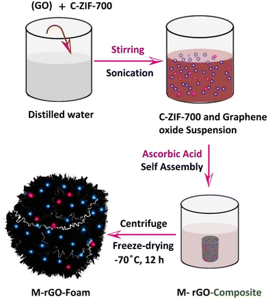 | ||
| Fig. 1 Schematic representation of the formation method of the M-rGO foam from C-ZIF-700 and graphene oxide. | ||
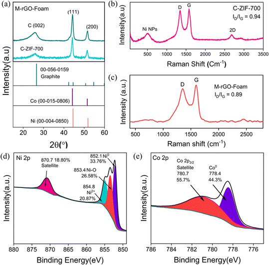 | ||
| Fig. 2 a) XRD patterns of the C-ZIF-700 and M-rGO foam, b and c) Raman scattering spectra of the C-ZIF-700 and M-rGO foam. XPS spectra of M-rGO foam (d) Ni2p and (e) Co2p. | ||
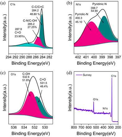
XPS spectra of C-ZIF-700 (Fig. S1†) and M-rGO foam (a) C1s (b) N1s (c) O1s, and (d) XPS survey confirmed the desired levels of C, N, and O peaks from the deconvolution of C1s, N1s, and O1s spectra, which confirmed the extent oxygen functionality on the surface carbon and nitrogen (Fig. 3). Primarily, the rGO foam structure was based on graphitic carbon, which also contained mainly pyridinic and pyrrolic nitrogen (Fig. 3(a) and (b)). The calibrated asymmetric graphitic peaks at 284.23 eV, 285.24, and 287.96 corresponded to C–C, C–OH, C![[double bond, length as m-dash]](https://www.rsc.org/images/entities/char_e001.gif) O groups, respectively, for the M-rGO foam. The deconvoluted N 1s XPS spectra corresponded to mainly pyridinic (∼398.78 eV, 52.39%), pyrrolic (∼400.36 eV, 47.61%) N-sites (Fig. 3b). Moreover, O1s spectra (Fig. 3c) corresponded to C
O groups, respectively, for the M-rGO foam. The deconvoluted N 1s XPS spectra corresponded to mainly pyridinic (∼398.78 eV, 52.39%), pyrrolic (∼400.36 eV, 47.61%) N-sites (Fig. 3b). Moreover, O1s spectra (Fig. 3c) corresponded to C![[double bond, length as m-dash]](https://www.rsc.org/images/entities/char_e001.gif) O and C–OH functionalities at 531.5 and 532.6 eV, respectively. Furthermore, the survey spectra confirmed the carbon and oxygen-rich composition in the M-rGO foam (Fig. 3d).
O and C–OH functionalities at 531.5 and 532.6 eV, respectively. Furthermore, the survey spectra confirmed the carbon and oxygen-rich composition in the M-rGO foam (Fig. 3d).
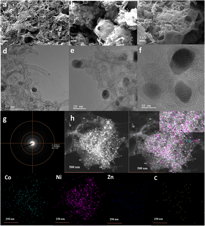
Field-emission scanning electron microscopy (FE-SEM) images of M-rGO foam at 10 μm (a), 2 μm (b), and 1 μm (c) scales are shown in Fig. 4. A porous C-ZIF-700 with the ideal rhombic dodecahedral shape of ZIF-8 was transformed into a layered topology, possibly because of the greater electronegativity of Ni2+ leading to the formation of a layered structure.31 A mixed metallic ZIF grown on rGO foam exhibited sheet-like 2D designs by numerous overlapping;32 however, uniformly grown sheets of M-ZIF layers were stacked one over the other. In our case, deviation from the rhombohedral shape of ZIF-8 transformed into a 2D sheet-like shape and layered topology due to the electronegativity of Ni2+.
The transmission electron microscopy (TEM) images of M-rGO foam at 50 nm (d), 20 nm (e), and 10 nm (f) scales showed the encapsulation of metal nanoparticles in the M-rGO foam network (Fig. 4). TEM of C-ZIF-700 contains tubular morphology with the distribution of metal nanoparticles, which was retained partially in M-rGO foam, as seen in Fig. 4(d and e) and (Fig. S2†).33 Moreover, rGO retained the foam-like morphology with pores, as reported previously for materials prepared using the chemical reduction method (Fig. S3†).34–37Fig. 4g reveals the high-angle annular dark-field scanning transmission electron microscopy (HAADF-STEM) electron image. The electron microscopy image of M-rGO foam shown in Fig. 4h reveals the presence of Co (green), Ni (violet), Zn (blue), and C (yellow) with the predominance of Ni NPs.
Electrochemical measurements
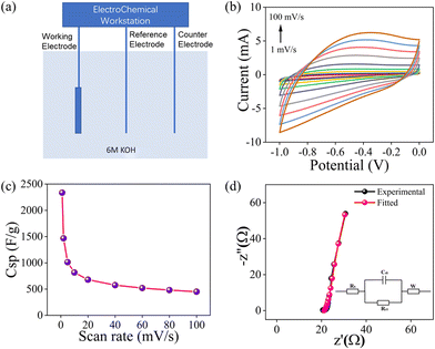
![[thin space (1/6-em)]](https://www.rsc.org/images/entities/char_2009.gif) 000 cycles. The electrochemical impedance spectroscopy (EIS) tests on the synthesized materials were carried out and the data are shown in Fig. 5d. It indicated its lower charge transfer resistance Rct value, suggesting higher reaction kinetics properties. The intercept on the objective (x) impedance axis of the Nyquist plot represents the comparable series resistance (RESR). Concurrently, information regarding charge transfer resistance is offered by the diameter of the semicircle (RCT). A range of resistance values was computed by employing the Randle circuit, where CDL denotes double-layer capacitance, for the purpose of fitting. Additional constituents, such as the W (Warburg element), offer insights into the transition from the lower to the higher frequency range and the disruptions caused by the electrode's uneven porosity. The low RESR (21.6 Ω), demonstrated by the M-rGO foam, explains its high capacitance value.
000 cycles. The electrochemical impedance spectroscopy (EIS) tests on the synthesized materials were carried out and the data are shown in Fig. 5d. It indicated its lower charge transfer resistance Rct value, suggesting higher reaction kinetics properties. The intercept on the objective (x) impedance axis of the Nyquist plot represents the comparable series resistance (RESR). Concurrently, information regarding charge transfer resistance is offered by the diameter of the semicircle (RCT). A range of resistance values was computed by employing the Randle circuit, where CDL denotes double-layer capacitance, for the purpose of fitting. Additional constituents, such as the W (Warburg element), offer insights into the transition from the lower to the higher frequency range and the disruptions caused by the electrode's uneven porosity. The low RESR (21.6 Ω), demonstrated by the M-rGO foam, explains its high capacitance value.
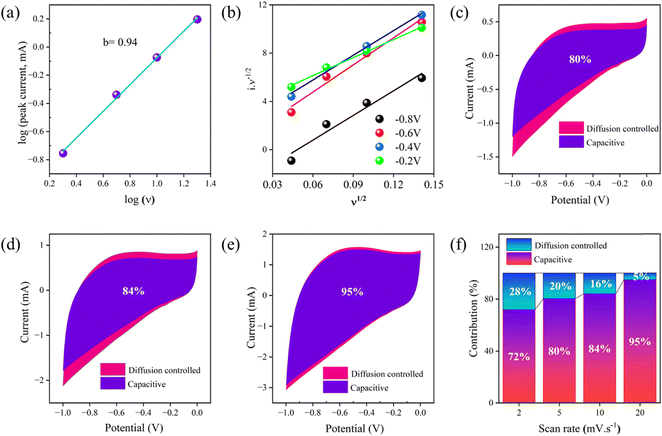
Notably, to understand the mechanism of charge storage contribution clearly, the intrinsic kinetic behaviour of the electrode was intensively studied from the CV curves. From the CV curve, the response of current according to the increment of the scan rate can be evaluated using the formula of power law and can be demonstrated in eqn (1)
| I = aνb | (1) |
| I = k1ν + k2ν1/2 | (2) |
Here k1ν and k2ν1/2 represent the contribution of current from the surface capacitive and diffusion-controlled processes, respectively. The k1 and k2 values can be extracted from the slope and intercept, respectively, and the corresponding slopes and intercepts were calculated from a linear fit of the i/ν1/2vs. ν1/2 plot given in Fig. 6(b). Fig. 6(c–e) represents the percentage of surface capacitive contribution and diffusion-controlled contribution out of overall capacitance of the as-prepared M-rGO foam in 6 M KOH electrolyte at scan rates of 2 (Fig. S7†) 5, 10, and 20 mV s−1. Fig. 6(f) shows that with the gradual increase in the scan rates, the surface capacitive contribution increases in a continuous ascending way from 72% to 95%, which suggested that the as-synthesized M-rGO foam had electrical double-layer capacitance (EDLC) properties.
Symmetric supercapacitor properties study
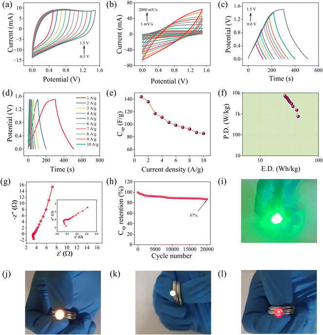
To strongly support the above experimental data, two electrode symmetric supercapacitor devices (SSD) were fabricated for real field applications by taking an equal mass of 1 mg of active material on the cathode and anode sides separated by polyvinylidene fluoride (PVDF) membrane, which was soaked in 6 M KOH electrolyte to measure the supercapacitance properties. The as-fabricated SSD shows quasi-rectangular CV curves with a potential window of 1.5 V, attributed to its potential for supercapacitor application. The quasi-rectangular CV plot may be accredited due to the non-faradaic capacitive contribution of the electrodes. As seen in Fig. 7(a), as the potential window exceeded 1.5 V, a sharpened upturn came off at the terminal of the CV curve, indicating that, beyond 1.5 V, partial polarization occurs at the electrode-electrolyte interface. The CV curves at different scan rates were investigated, as shown from the data in Fig. 7(b). As the scan rates increase from 1 mV s−1 to 2000 mV s−1, a consistent quasi-rectangular CV curve was obtained, which suggests the charge storage mechanism is a capacitive contribution type. Likewise, the GCD plot was investigated at different potential windows at fixed current densities of 1 A g−1, as shown in Fig. 7(c). The GCD plots at different current densities are shown in Fig. 7(d). The symmetric and linear GCD plot indicated that the charge storage mechanism was the electric double layer (EDL) type. The specific capacitance of the as-fabricated SSD was calculated from the GCD curves and shown in Fig. 7(e). The SSD achieved an excellent specific capacitance of 143.79 F g−1 at 1 A g−1. It can be seen from the capacitance plot that the fabricated SSD shows a high capacitance value of 85.6 F g−1, even at a higher current density value of 10 A g−1. The corresponding Ragone plot at different current densities is presented in Fig. 7(f), which shows a maximum energy density of 44.93 Wh kg−1 at a power density of 749.9 W kg−1, and the energy density was 26.75 Wh kg−1 at the respective power density of 7224.3 W kg−1. The energy density performance of the fabricated SSD is compared with graphene-foam and porous materials from the previous related literature on a supercapacitor device and the results are tabulated in Table S1.† Meanwhile, the EIS was carried out for the fabricated SSD and the data are shown in Fig. 7(g), which indicates that the devices exhibited a very low Rct value attributed to the outstanding electrical conductivity. Strikingly, the fabricated SSD exhibited remarkable capacitance retentions of 87% after 20![[thin space (1/6-em)]](https://www.rsc.org/images/entities/char_2009.gif) 000 CV cycles, which is attributed to its potential application towards supercapacitor applications, as shown in Fig. 7(h). Pseudocapacitive performance of spinel cobalt oxide (Co3O4) spinel cobaltite at a current density of 1 Ag-1 exhibits 92.1% of its initial capacitance after 5000 cycles.38 Surface modification of MOF-derived cobalt-based hybrid nanostructures offers pseudocapacitive features with capacitive retention of 96.8% after 10
000 CV cycles, which is attributed to its potential application towards supercapacitor applications, as shown in Fig. 7(h). Pseudocapacitive performance of spinel cobalt oxide (Co3O4) spinel cobaltite at a current density of 1 Ag-1 exhibits 92.1% of its initial capacitance after 5000 cycles.38 Surface modification of MOF-derived cobalt-based hybrid nanostructures offers pseudocapacitive features with capacitive retention of 96.8% after 10![[thin space (1/6-em)]](https://www.rsc.org/images/entities/char_2009.gif) 000 cycles, which has a resemblance to our metallic cobalt-installed foam.39 The presence of Co centers is responsible for producing high graphitic carbon. Co-based ZIF-67 produces high crystallinity but a low percentage of nitrogen centers. Whereas, Zn captures a larger percentage of nitrogen but produces amorphous carbon. Thus, the tri-metal doped in a heterostructure results in a good percentage of nitrogen and crystallinity. All these contributions result in lower Rct values with the multimetallic centers.
000 cycles, which has a resemblance to our metallic cobalt-installed foam.39 The presence of Co centers is responsible for producing high graphitic carbon. Co-based ZIF-67 produces high crystallinity but a low percentage of nitrogen centers. Whereas, Zn captures a larger percentage of nitrogen but produces amorphous carbon. Thus, the tri-metal doped in a heterostructure results in a good percentage of nitrogen and crystallinity. All these contributions result in lower Rct values with the multimetallic centers.
To support the above experimental data, two fabricated SSDs were connected in series to double the voltage, which can easily power up 1.5 V light emitting diode (LED) in different colors, i.e., white, green, yellow, and red with a very high brightness level. The photograph of the LED glowing when connecting two SSDs in series is shown in Fig. 7(i–l), again suggesting its real filed application towards supercapacitor devices. Table S1† lists a range of graphenic foam materials with metal doping, which showed corresponding energy densities in Wh kg−1 among which metal species doped electrodes are faradaic for holding charge density for longer cycles in the form of capacitance retention. In this context, Ni-foam has been a more frequent candidate; however, bimetallic hybrids or metallic architectures with enhanced capacitance for high-performance energy storage devices are not frequently known. Multidimensional carbon matrix acts as a source for fabricating two-dimensional hybrid materials and heterostructures.40 Specific capacitance LiMnFePO4@C![[thin space (1/6-em)]](https://www.rsc.org/images/entities/char_2009.gif) :
:![[thin space (1/6-em)]](https://www.rsc.org/images/entities/char_2009.gif) graphite at a 5
graphite at a 5![[thin space (1/6-em)]](https://www.rsc.org/images/entities/char_2009.gif) :
:![[thin space (1/6-em)]](https://www.rsc.org/images/entities/char_2009.gif) 1 helps in intercalation and de-intercalation of Li+ ions in graphite as a hybrid cathode where carbon incorporation is effective for improvement.41,42 Carbon frameworks are often designed with encapsulated and highly-dispersed metal nanostructure for reversible capacity after longer cycles with about 70% capacity storage.43 As a consequence of M-rGO foam with multimetallic contributions, carbon structure in the form of dots forms the cross-stacked structure for enhanced ion storage with high capacitance with easy transport of electron and alkali metal ions (Na+).44
1 helps in intercalation and de-intercalation of Li+ ions in graphite as a hybrid cathode where carbon incorporation is effective for improvement.41,42 Carbon frameworks are often designed with encapsulated and highly-dispersed metal nanostructure for reversible capacity after longer cycles with about 70% capacity storage.43 As a consequence of M-rGO foam with multimetallic contributions, carbon structure in the form of dots forms the cross-stacked structure for enhanced ion storage with high capacitance with easy transport of electron and alkali metal ions (Na+).44
Conclusions
Graphene oxide (GO) was mixed with C-ZIF-700, a multimetallic MWCNT-containing composite, followed by self-assembly using ascorbic acid as a self-assembly agent, which resulted in a Ni-rGO-composite as a single piece. This piece was collected from the medium, centrifuged, and freeze-dried at −70 °C to form Ni-rGO foam as metal (Ni) decorated composite foam. While forming a composite within graphene oxide and M-ZIF-700 NC wherein L-ascorbic acid plays the role of reducing agent in the aqueous medium at a slightly higher temperature (75 °C) for a longer time (8 h). Here, the L-ascorbic acid (vitamin C) acts as a reducing agent to convert graphene oxide to reduced graphene oxide. M-rGO foam architecture interfaced with doped metal nanoparticles such as cobalt, nickel, and zinc for capacitance enhancement because of the possible ionic conductivity in a hierarchical metal-doped architecture. M-rGO foam delivered an outstanding gravimetric capacitance of 1013.47 F g−1 at a scan rate of 5 mV s−1 and retained an extraordinary gravimetric capacitance of 450.81 F g−1 even at a higher scan rate of 100 mV s−1 with high-rate capability. Prolonged capacitance retention of 94% occurred even after 10![[thin space (1/6-em)]](https://www.rsc.org/images/entities/char_2009.gif) 000 cycles. The symmetric supercapacitor device (SSD) of M-rGO foam achieved an ultrahigh energy density of 44.93 Wh kg−1 at a power density of 749.9 W kg−1, which is attributed to a promising application of the symmetric supercapacitor device. Cyclability test of M-rGO foam-based as-fabricated device exhibited potential light-emitting applications.
000 cycles. The symmetric supercapacitor device (SSD) of M-rGO foam achieved an ultrahigh energy density of 44.93 Wh kg−1 at a power density of 749.9 W kg−1, which is attributed to a promising application of the symmetric supercapacitor device. Cyclability test of M-rGO foam-based as-fabricated device exhibited potential light-emitting applications.
Conflicts of interest
Authors have no conflict of interest to declare.Acknowledgements
SD wishes to acknowledge research funding support by the Department of Biotechnology, Ministry of Science and Technology, Government of India for the grant number BT/RLF/Re-entry/41/2017 under DBT Ramalingaswami Re-entry Fellowship (2019–2024) and DBT-Energybioscience-Biofuels research grant (2022–2025 BT/PR38594/PBD/26/795/2020). BKJ acknowledges CSIR (HCP-42, OLP-65), New Delhi, India, for the financial support. LP thanks CSIR for the fellowship. The authors are thankful to the National Science and Technology Council (NSTC), Taiwan for the funding support (111-2124-M-002-021 and 111-2628-E-002-008). Also, financial support by the Center of Atomic Initiative for New Materials, National Taiwan University, from the Featured Areas Research Center Program within the framework of the Higher Education Sprout Project by the Ministry of Education in Taiwan (111L900801), is acknowledged.References
- Z. Chen, W. Ren, L. Gao, B. Liu, S. Pei and H.-M. Cheng, Nat. Mater., 2011, 10, 424–428 CrossRef CAS PubMed.
- X. Xu, C. Guan, L. Xu, Y. H. Tan, D. Zhang, Y. Wang, H. Zhang, D. J. Blackwood, J. Wang, M. Li and J. Ding, ACS Nano, 2020, 14, 937–947 CrossRef CAS PubMed.
- S. K. Das, L. Pradhan, B. K. Jena and S. Basu, Carbon, 2023, 201, 49–59 CrossRef CAS.
- B. Yao, H. Peng, H. Zhang, J. Kang, C. Zhu, G. Delgado, D. Byrne, S. Faulkner, M. Freyman, X. Lu, M. A. Worsley, J. Q. Lu and Y. Li, Nano Lett., 2021, 21, 3731–3737 CrossRef CAS PubMed.
- J. Du, Q. Cao, X. Tang, X. Xu, X. Long, J. Ding, C. Guan and W. Huang, Chem. Eng. J., 2021, 416, 127885 CrossRef CAS.
- T. Du, Z. Xiong, L. Delgado, W. Liao, J. Peoples, R. Kantharaj, P. R. Chowdhury, A. Marconnet and X. Ruan, Nat. Commun., 2021, 12, 4915 CrossRef CAS PubMed.
- S. K. Das, S. Kamila, B. Satpati, M. Kandasamy, B. Chakraborty, S. Basu and B. K. Jena, J. Power Sources, 2020, 471, 228465 CrossRef CAS.
- S. H. Noh, H. Park, W. Eom, H. B. Lee, D. J. Kang, J. Y. Cho, T. H. Sung and T. H. Han, ACS Appl. Mater. Interfaces, 2020, 12, 10763–10771 CrossRef CAS PubMed.
- R. Patil and S. Dutta, Adv. Mater. Interfaces, 2023, 10, 2202137 CrossRef CAS.
- S. Kamila, B. Chakraborty, S. Basu and B. K. Jena, J. Phys. Chem. C, 2019, 123, 24280–24288 CrossRef CAS.
- H. Ding, L. Xu, C. Wen, J.-J. Zhou, K. Li, P. Zhang, L. Wang, W. Wang, W. Wang, X. Xu, W. Ji, Y. Yang and L. Chen, Chem. Eng. J., 2022, 440, 135847 CrossRef CAS.
- B. Mohanty, L. Giri and B. K. Jena, Energy Fuels, 2021, 35, 14304–14324 CrossRef CAS.
- X. Guo, H. Yang, Q. Liu, J. Liu, R. Chen, H. Zhang, J. Yu, M. Zhang, R. Li and J. Wang, Chem. Eng. J., 2020, 382, 122850 CrossRef CAS.
- L. Ge, D. Wang, P. Yang, H. Xu, L. Xiao, G.-X. Zhang, X. Lu, Z. Duan, F. Meng, J. Zhang and M. An, Nanoscale, 2019, 11, 17010–17017 RSC.
- H. Yin, D. Li, Z. Chi, Q. Zhang, X. Liu, L. Ding, S. Li, J. Liu, Z. Guo and L. Wang, J. Mater. Chem. A, 2021, 9, 17865–17875 RSC.
- R. Ahmad, N. Iqbal, M. M. Baig, T. Noor, G. Ali and I. H. Gul, Electrochim. Acta, 2020, 364, 137147 CrossRef CAS.
- S. Kamila, P. Mane, R. I. Mohanty, B. Chakraborty and B. K. Jena, Electrochim. Acta, 2021, 399, 139357 CrossRef CAS.
- Y. Lei, G. Zhang, Q. Zhang, L. Yu, H. Li, H. Yu and Y. He, Nat. Commun., 2021, 12, 4483 CrossRef CAS PubMed.
- D. Yu, Q. Shao, Q. Song, J. Cui, Y. Zhang, B. Wu, L. Ge, Y. Wang, Y. Zhang, Y. Qin, R. Vajtai, P. M. Ajayan, H. Wang, T. Xu and Y. Wu, Nat. Commun., 2020, 11, 927 CrossRef CAS PubMed.
- H. Zou, B. He, P. Kuang, J. Yu and K. Fan, Adv. Funct. Mater., 2018, 28, 1706917 CrossRef.
- S. Kamila, B. Mohanty, A. K. Samantara, P. Guha, A. Ghosh, B. Jena, P. V. Satyam, B. K. Mishra and B. K. Jena, Sci. Rep., 2017, 7, 8378 CrossRef PubMed.
- H. Guo, A. Zhang, H. Fu, H. Zong, F. Jin, K. Zhao and J. Liu, Chem. Eng. J., 2023, 453, 139633 CrossRef CAS.
- J. Zhao, N. Yi, X. Ding, S. Liu, J. Zhu, A. C. Castonguay, Y. Gao, L. D. Zarzar and H. Cheng, Chem. Eng. J., 2023, 456, 140956 CrossRef CAS PubMed.
- F. Wang, Y. Liu, H. Zhao, L. Cui, L. Gai, X. Han and Y. Du, Chem. Eng. J., 2022, 450, 138160 CrossRef CAS.
- N. Kumar, L. Pradhan and B. K. Jena, Wiley Interdiscip. Rev.: Energy Environ., 2022, 11(1), e415 CAS.
- G. Qian, J. Chen, T. Yu, L. Luo and S. Yin, Nano-Micro Lett., 2021, 13, 77 CrossRef PubMed.
- S. Liu, L. Kang, J. Henzie, J. Zhang, J. Ha, M. A. Amin, M. S. A. Hossain, S. C. Jun and Y. Yamauchi, ACS Nano, 2021, 15, 18931–18973 CrossRef CAS PubMed.
- S. Liu, L. Kang and S. C. Jun, Adv. Mater., 2021, 33, 2004689 CrossRef CAS PubMed.
- S. Liu, L. Kang, J. Zhang, S. C. Jun and Y. Yamauchi, ACS Energy Lett., 2021, 6, 4127–4154 CrossRef CAS.
- T. Qiu, J.-G. Yang, X.-J. Bai and Y.-L. Wang, RSC Adv., 2019, 9, 12737–12746 RSC.
- L. Han, H. Cheng, W. Liu, H. Li, P. Ou, R. Lin, H.-T. Wang, C.-W. Pao, A. R. Head and C.-H. Wang, Nat. Mater., 2022, 21, 681–688 CrossRef CAS PubMed.
- M. Ding, J. Chen, M. Jiang, X. Zhang and G. Wang, J. Mater. Chem. A, 2019, 7, 14163–14168 RSC.
- R. Patil, N. Kumar, S. Bhattacharjee, B. M. Matsagar, P. C. Han, K. C. W. Wu, R. R. Salunkhe, A. Bhaumik and S. Dutta, Mater. Today Chem., 2023, 28, 101374 CrossRef CAS.
- D. Gogoi, M. R. Das and N. N. Ghosh, ACS Omega, 2022, 7, 11305–11319 CrossRef CAS PubMed.
- R. Tian, Y. Zhang, Z. Chen, H. Duan, B. Xu, Y. Guo, H. Kang, H. Li and H. Liu, Sci. Rep., 2016, 6, 19195 CrossRef CAS PubMed.
- X. Xu, L. Pan, Y. Liu, T. Lu, Z. Sun and D. H. C. Chua, Sci. Rep., 2015, 5, 1–9 Search PubMed.
- X. Xu, Z. Sun, D. H. C. Chua and L. Pan, Sci. Rep., 2015, 5, 11225 CrossRef CAS PubMed.
- S. Liu, D. Ni, H.-F. Li, K. N. Hui, C.-Y. Ouyang and S. C. Jun, J. Mater. Chem. A, 2018, 6, 10674–10685 RSC.
- S. Liu, L. Kang, J. Zhang, E. Jung, S. Lee and S. C. Jun, Energy Stor. Mater., 2020, 32, 167–177 Search PubMed.
- J.-M. Cao, I. V. Zatovsky, Z.-Y. Gu, J.-L. Yang, X.-X. Zhao, J.-Z. Guo, H. Xu and X.-L. Wu, Prog. Mater. Sci., 2023, 135, 101105 CrossRef CAS.
- X.-T. Wang, Y. Yang, J.-Z. Guo, Z.-Y. Gu, E. H. Ang, Z.-H. Sun, W.-H. Li, H.-J. Liang and X.-L. Wu, J. Mater. Sci. Technol., 2022, 102, 72–79 CrossRef CAS.
- Q.-M. Yin, Z.-Y. Gu, Y. Liu, H.-Y. Lü, Y.-T. Liu, Y.-N. Liu, M.-Y. Su, J.-Z. Guo and X.-L. Wu, Adv. Funct. Mater., 2023, 33, 2304046 CrossRef CAS.
- S. Wu, F. Xu, Y. Li, C. Liu, Y. Zhang and H. Fan, J. Colloid Interface Sci., 2023, 649, 741–749 CrossRef CAS PubMed.
- B. Qin, M. Wang, S. Wu, Y. Li, C. Liu, Y. Zhang and H. Fan, Chin. Chem. Lett., 2023, 108921, DOI:10.1016/j.cclet.2023.108921.
Footnotes |
| † Electronic supplementary information (ESI) available. See DOI: https://doi.org/10.1039/d3lf00226h |
| ‡ Equal contribution from authors. |
| This journal is © The Royal Society of Chemistry 2024 |

