Interfacial analysis of the ion-transport process controlling the steady-state current in a two-phase electrodeposition system using polyelectrolyte membranes†
Received
3rd April 2024
, Accepted 16th May 2024
First published on 28th May 2024
Abstract
Effluent-free selective copper electrodeposition based on ion transport via ion-exchange reactions within polyelectrolyte membranes is described. The new solid-phase electrodeposition system includes a thin layer of electrolyte solution between the anode and the membrane that comes into contact with the cathode. This layer was introduced to enable the electrolyte solution to be circulated to maintain the concentration of copper ions in the solution phase during electrodeposition. This membrane–solution layered system has a greater steady-state current density under constant-voltage electrodeposition compared with the previous system in which the membrane was sandwiched between the electrodes. The higher current density was attributed to the higher ion penetration rate at the interface between the electrolyte solution and the membrane, as verified by the results of the numerical analysis of the ion transport kinetics in the new system. By positioning the anode such that it is set slightly apart from the polyelectrolyte membrane to allow the electrolyte phase to be introduced, but as close as possible to it, a current density that was at maximum 50% greater than that of the sandwiched system was realized at steady state. This increase, which is attributed to the maximum ion penetration rate and minimum resistivity of the electrolyte layer, ensures a more efficient deposition setup for high-performance electrodeposition.
Introduction
The electrodeposition of metals is one of the most important techniques for the fabrication of microelectronics and semiconductor elements in printed circuit boards and electronic device manufacturing.1–6 From an industrial perspective, the management of electrodeposition baths is crucial for maintaining the product quality, productivity, and long-term stability of the bath, which includes the bath temperature, concentration of metal salts, supporting electrolytes, and various additives.7–17 Although these parameters have been optimized to achieve the desirable deposition rate depending on the type and morphology of the product, environmental issues in the form of the generation of mist, sludge, and waste effluent during the electrodeposition process have become apparent. Additionally, existing electrodeposition processes have been developed for substrates with large surface areas and for the large-scale production of electronic components, and are not suitable for the recent demand for small-lot, site-selective, and multiproduct device microfabrication. Therefore, a high-performance deposition system that allows the site-selective electrodeposition of metals without the generation of large amounts of effluent needs to be developed from an environmental and cost perspective.
Several site-selective deposition techniques have been developed. These techniques, such as brush plating18–20 and localized electrodeposition using porous media,21 rely on confinement to the area where electrodeposition occurs at the substrate–solution interface. Other deposition techniques employ fine nozzles and hollow AFM cantilevers to confine the electrolyte solution for successful serial fabrication of metal microstructures.22–25 Recently, we reported a novel method for metal electrodeposition using polyelectrolyte membranes attached to a cathode substrate (solid electrodeposition, SED).26 SED, which enables the deposition of metals directly on the cathode surface from metal ions in solid polyelectrolyte membranes, has desirable advantages, including a higher deposition rate, site selectivity, and deposition using an electrolyte solution with a lower concentration without additives. Owing to the utilization of solid polyelectrolyte membranes as ion transport media during the electrodeposition process, the system produces no mist, sludge, or waste effluent. Our previous experimental and theoretical study, conducted on a system in which the membrane was completely sandwiched between the cathode plate and anode mesh, demonstrated that the copper ion transport kinetics were controlled by the reaction that involves the penetration of ions from the electrolyte solution into the polyelectrolyte membranes. In addition, the steady-state current density of the system was determined by maintaining a strict balance between the voltage-dependent deposition rate and concentration-dependent penetration rate of the copper ions.26 Herein, we describe a related system based on polyelectrolyte membranes that are sandwiched between the cathode and electrolyte solution. In this system, ion penetration is more efficient than that in the previous system in which the copper mesh anode came into contact with the membrane (Fig. 1). The new system allows the kinetic control of ion transport inside the polyelectrolyte membrane simply by adjusting the distance between the polyelectrolyte membrane and the anode, thus providing an effective methodology for controlling the steady-state current density in SED systems. A generalized theoretical model is proposed to describe the current passing between the electrodes during electrodeposition in the present SED system, which complements our previous SED system. The new SED setup, experimental and theoretical analyses of the ion transport kinetics, and the implications of this system are presented.
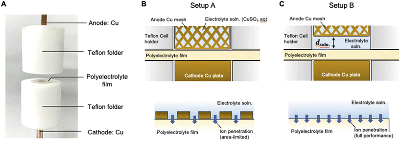 |
| | Fig. 1 (A) Photographic image of the SED cell used for the present study. (B) Schematic of the cross-section of the SED cell where the polyelectrolyte membrane is sandwiched between the cathode Cu rod and anode Cu mesh grid (upper image) and schematic of the ion transport process at the interface between the polyelectrolyte membrane and electrolyte solution (bottom image). (C) Schematic of a cross-section of the SED cell where the electrolyte solution phase is introduced with a distance d between the anode mesh grid and polyelectrolyte membrane (upper image) and schematic of the ion transport process at the interface between the polyelectrolyte membrane and electrolyte solution. This arrangement allows the ion penetration process to reach its full potential (bottom image). | |
Experimental
Chemicals
Copper sulfate (CuSO4·5H2O) and sulfuric acid (H2SO4) were purchased from Wako Chemical Co., and used without further purification. Perfluorosulfonic acid membranes (Nafion®) with a thickness of 200 μm in a water-swollen state (N117) were purchased from DuPont and were used as the cation exchange membranes. Before use, the membranes were treated with aqueous sulfuric acid at 60 °C for 2 h to ensure that they were in their fully acidic forms. A pure copper rod (5.0 mm in diameter) and copper mesh grids (100 mesh, 32.6% aperture ratio, Nilaco Co.) were used as the cathode and anode, respectively.
SED setup
The membranes were stored in an aqueous solution of copper sulfate (1.0 M) for 30 min at 30 °C. After the copper ions had undergone complete cation exchange with the protons, the membranes that were fully saturated with copper ions were placed at the top of the hole (diameter: 5.0 mm) in a Teflon folder (Fig. 1A). The membranes were sandwiched between copper rods (cathode) and a mesh (anode). The aqueous solution of copper sulfate was circulated (2.0 mL min−1) between the membrane and anode using a micropump (403VertU/VM2, WATSON MARLOW Co. Ltd.) (ESI,† Fig. S1). A micrometer was used to adjust the distance between the membrane and anode in the range of 0–2000 μm. The scale of the micrometer was plotted as a function of the thickness of the pre-set (overlapped) plate for calibration of distance between the anode and polyelectrolyte membrane. The data demonstrate that the scale of the micrometer is in good agreement with that of the actual distance in the present experimental setup (ESI,† Fig. S2). Current–time curves were acquired using an electrometer (SourceMeter 2612A; KEITHLEY Instruments).
Results and discussion
SED system consisting of polyelectrolyte membranes and electrolyte solution
Fig. 1B and C show the schematics of the previous and present SED setups to show the respective structures of the electrodeposition cell. The polyelectrolyte membranes were sandwiched between the cathode copper plate and anode copper mesh (setup A, Fig. 1B) and between the cathode and electrolyte solution (setup B, Fig. 1C), respectively. Our previous study on setup A demonstrated that at constant voltage electrodeposition, the copper ions penetrated the solid, water-swollen polyelectrolyte membrane from the electrolyte solution, diffused through the membrane via an ion exchange reaction, and were finally reduced on the cathode surface.26 Theoretical modelling and our experimental results revealed that ion penetration from the electrolyte solution into the polyelectrolyte membrane is the rate-determining step at the applied voltage up to 1.0 V using a 200 μm-thick membrane.26 During constant-voltage electrodeposition, the current density decreases in the early stage of electrodeposition because of the decrease in the concentration of copper ions in the polyelectrolyte membrane, after which the current density stabilizes when the system reaches the steady state because of the balance between the deposition and penetration rates (Fig. 2). In setup A, the interfacial area where copper ions can penetrate the polyelectrolyte membrane was restricted to the interface between the polyelectrolyte membrane and electrolyte solution (Fig. 1B). In this case, because it is difficult for the copper ions to dissolve directly from the solid anode into the solid polyelectrolyte at the anode–polyelectrolyte interface, the ions are mostly supplied from the electrolyte solution at the solution–polyelectrolyte interface. However, the separation of the anode from the surface of the polyelectrolyte membrane in setup B allows the penetration of copper ions more effectively than that in setup A, thereby enabling the ion penetration to reach its full potential in the SED system (Fig. 1C). In practice, the current at steady-state increases from 32 mA cm−2 to 47 mA cm−2 at constant voltage electrodeposition (0.5 V) in setup B as compared with setup A at 30 °C (Fig. 2). Therefore, the introduction of a solution phase between the polyelectrolyte membrane and anode is an effective approach for maximizing the penetration rate of copper ions and thus the current density of the SED system.
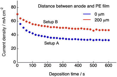 |
| | Fig. 2 Variation in the current density with the deposition time at 0.3 V, measured using the SED cell for two different distances between the anode mesh grid and polyelectrolyte membrane (0 and 200 μm), using an aqueous solution of CuSO4 (500 mM) at 30 °C. | |
Cell constants
To describe the ion transport behavior of the present SED setup, the cell constant of setup B needs to be determined. This constant is dependent on the positioning of the electrode (area, morphology, and distance) and space (volume) in the polyelectrolyte membrane, where the copper ions are mobile and contribute to the current. The cell constant can be expressed as:where R, ρ, and C represent the resistivity, specific resistance, and cell constant, respectively. In SED setup B, the total resistivity (Rtotal) between the electrodes is the sum of the resistivity of the polyelectrolyte (RPE) and the solution phase (Rsoln) and can be expressed as:| | | Rtotal = RPE + Rsoln = ρPECPE + ρsolnCsoln | (2) |
where ρPE, ρsoln, CPE, and Csoln are the specific resistivities and cell constants of the polyelectrolyte membrane and electrolyte solution, respectively. Note that Csoln can be numerically expressed as:where dsoln and A are the distance between the anode and polyelectrolyte membrane and the surface area of the anode, respectively. Rsoln can be calculated using ρsoln at known concentrations and geometric parameters (dsoln and A). However, the region in which copper ions are transported in the polyelectrolyte phase during electrodeposition is difficult to determine. This is because copper ions that do not reside directly below the electrolyte solution and/or above the cathode are also mobile as a result of ion exchange reactions resulting from the concentration gradient inside the polyelectrolyte membrane (Fig. 3) during electrodeposition. Therefore, the value of CPE must be determined experimentally using the following relationship:| |  | (4) |
where κPE, Λ and [CS(PE)] are the specific conductivity, molar electrical conductivity of the polyelectrolyte membrane fully saturated with copper ions, and concentration of copper ions inside the polyelectrolyte membrane, respectively. Because Λ is known to be ca. 2.0 S mol−1 cm2, CPE is the only unknown variable in eqn (4).26 Therefore, the value of CPE can be estimated from the initial current (the current observed at t = 0 for constant-voltage electrodeposition, where t is the deposition time) using eqn (4). In fact, CPE is almost constant at 0.032–0.038 cm−1 for the range of distances (dsoln) of 0–1000 μm between the anode and polyelectrolyte membrane (Table 1). The value of Ctotal should therefore be proportional to dsoln, which can be attributed to an increase in the resistance of the electrolyte solution as a function of dsoln.
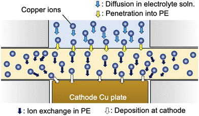 |
| | Fig. 3 Schematic of the ion transport process involving the diffusion of copper ions in electrolyte solution (light blue arrows), penetration of the interface between the polyelectrolyte membrane and electrolyte solution (yellow arrows), ion exchange in the polyelectrolyte membrane (black arrows) and deposition at the cathode surface (white arrows). | |
Table 1 Cell constants for the SED system for different distances (d) between the anode and polyelectrolyte film
|
d/μm |
0 |
500 |
1000 |
| Cell constant/cm−1 |
3.2 × 10⁻² |
3.3 × 10⁻² |
3.8 × 10⁻² |
Here, we consider the space in the polyelectrolyte membrane in which the copper ions can be mobile during electrodeposition. Although, as described above, the local transfer direction of copper ions inside the membrane is hardly prescribed, the region in which ion transport takes place inside the membrane could be roughly estimated from the experimentally determined cell constant using the following equation:
where
dPE and
S are the thickness of the polyelectrolyte membrane and apparent area of the membrane in which the copper ions are mobile during electrodeposition, respectively, under the assumption that the region for ion transport is cylindrical (
Fig. 4A). Based on the experimental results of the cell constants obtained for different areas of the cathode and the areas in which the electrolyte solution and membrane make contact, the diameter of the cylindrical region was calculated using the estimated value of
S using
eqn (5) (
Fig. 4B) and known
dPE (200 μm in the water-swollen state). The apparent radius of the ion-transfer region is slightly greater than the radius of the cathode (and the contact area between the electrolyte solution and membrane), indicating that ions in the membrane that are not in direct contact with the cathode or electrolyte solution are mobile during the electrodeposition process (
Fig. 3). The radius of the ion-transfer region is approximately 2.0 mm larger than that of the cathode, irrespective of the diameter of the cathode, and may be determined by the thickness (200 μm in the present case) of the membrane and the mobility of the ions inside the membrane. The resulting
CPE and estimated
S were used in the following section for the theoretical description of the ion transport and current in the present SED system.
 |
| | Fig. 4 (A) Schematic of the SED setup to define the apparent ion transfer region where copper ions are mobile during the electrodeposition process. (B) Difference in the apparent radius of the cylindrical ion transfer region and that of the contact area of the electrolyte solution (and also the area of the cathode) as a function of the distance between the anode and polyelectrolyte membrane. | |
Theoretical description of current under constant applied voltage
Here, we provide a theoretical description of the current–time characteristics of the present SED system under constant applied voltage. Based on the previous study for setup A, we first considered the model system to describe the ion transport kinetics between the electrodes for setup B (Fig. 5). In this model, copper ions (C) are adsorbed by pairs of sulfonic acid groups on the surface (CS(I)) in an interfacial layer in which the copper ions penetrate the polyelectrolyte membrane to form salts (CS(PE)).26 Regarding the ion transport kinetics of copper ions from the solution to the polyelectrolyte membrane, our previous experimental results demonstrated that the penetration of ions from the interfacial layer into the polyelectrolyte membrane is the rate-determining reaction. Because the electrolyte solution was circulated during the electrodeposition process in setup B, the concentration of the solution phase was considered to be constant, such that the resistivity (Rsoln) remained constant under an applied voltage. However, because the concentration of copper ions in the polyelectrolyte membrane changes as a function of the deposition time, the resistivity of the polyelectrolyte phase (RPE) is variable.
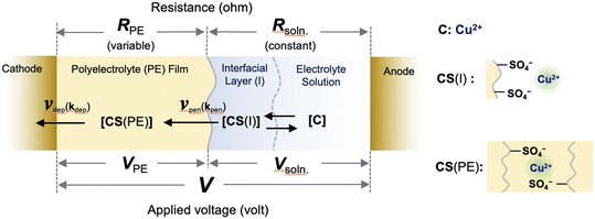 |
| | Fig. 5 Schematic of the reaction for SED setup B, including the surface adsorption of copper ions from the electrolyte solution into the interfacial layer, the penetration reaction from the interfacial layer into the polyelectrolyte membrane, and the deposition reaction at the cathode surface under an applied voltage. The symbols are defined in the text. | |
Under constant applied voltage, the time-dependent change in the concentration of Cu2+ ions in the polyelectrolyte membrane ([CS(PE)]) can be expressed as:26
| |  | (6) |
where
kpen,
kdep, CS(I),
S(PE), and
S0(PE) are the rate constant for the penetration reaction, rate constant for the deposition reaction, concentration of copper ions at the interfacial layer, concentration of pairs of sulfonic acid groups that are not bound with copper ions in the polyelectrolyte membrane, and initial concentration of pairs of sulfonic acid groups, respectively.
β (=
A/
S) is defined as the penetration power coefficient for ion penetration at the membrane–solution interface in this system,
26 that is, the areal ratio of the electrolyte solution/membrane interface (
A) to the apparent surface area of the cylindrical ion transfer region in the membrane (
S).
β represents the apparent efficiency of ion penetration in interfacial area
A for the ion transfer region with volume
V (=
S ×
dPE, where
dPE is the thickness of the membrane); the greater the value of
A (thus the greater the value of
β), the greater the penetration power becomes.
26 The rate constant of the deposition reaction (
kdep) can also be expressed as:
where
α is the coefficient of the voltage applied to the polyelectrolyte membrane,
VPE.
26 From Kirchhoff's second law,
27VPE can be expressed as:
| |  | (8) |
where
V is the applied voltage between electrodes. By combining
eqn (6)–(8), the following first-order nonlinear ordinary differential equation is obtained.
| |  | (9) |
In
eqn (8), when
dsoln = 0, a simpler differential equation, identical to the equation previously obtained for setup A,
26 was obtained, thereby demonstrating that
eqn (9) provides a general description of the ion transport kinetics of the SED system. Finally, the current–time curves for the present SED in setup B can be obtained from the time-dependent changes in [CS(PE)] obtained by conducting numerical analysis based on
eqn (9) and on the relationship between the current and [CS(PE)] (
eqn (4)).
We numerically analyzed the current–time curves recorded at constant applied voltage to calculate the deposition rate constant (kdep). This was accomplished by fitting the experimental curves with eqn (4) using the Runge–Kutta method with fourth-order accuracy (Fig. 6). Several systems, each with a different distance dsoln between the anode and polyelectrolyte membrane (from 0 to 2000 μm), were fitted, and the value of dsoln at different applied voltages provided the coefficient α, which was almost constant, although there are some errors (5–30% deviation) (Table 2). These results indicate that the coefficient α can determine the efficiency of charge transfer that enables copper ions to be reduced at the cathode surface, which is independent of dsoln.
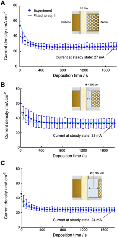 |
| | Fig. 6 Current density as a function of deposition time using 0.50 M CuSO4 solution at 30 °C for different cell setups with d = 0 (A), 200 μm (B) and 700 μm (C). Experimental data (blue dots) were fitted (light blue lines) to the equation (eqn (4)) using eqn (8) as [CS(PE)] by the Runge–Kutta method with fourth-order accuracy to determine the deposition rate constant (kdep). | |
Table 2 Coefficient (α) of voltage applied for the polyelectrolyte film for different distances (dsoln) between the anode and polyelectrolyte film
|
d
soln/μm |
0 |
250 |
500 |
1000 |
1500 |
2000 |
|
α/V−1 s−1 |
0.024 ± 0.004 |
0.029 ± 0.01 |
0.024 ± 0.006 |
0.024 ± 0.004 |
0.023 ± 0.004 |
0.023 ± 0.01 |
Steady-state current density
The steady-state current at constant-voltage electrodeposition in the SED system is an indication of the potential to achieve maximum current density at constant-current electrodeposition. The steady-state current at constant voltage (0.5 V) electrodeposition increased from 27 mA at dsoln = 0 μm to 33 mA at dsoln = 200 μm and then decreased to 24 mA at dsoln = 700 μm in the case of 0.50 M CuSO4 solution at 30 °C (Fig. 6). Fig. 7 summarizes the steady-state currents for setups A and B as functions of dsoln from 0 to 1000 μm, using electrolyte solutions with concentrations of 0.1 and 1.0 M. The dependence of the steady-state current on dsoln demonstrates that the experimental data are in good agreement with the values calculated using eqn (4) and (9) at infinite t. The initial rapid increase in the steady-state current at dsoln = 100 μm compared with that at dsoln = 0 μm could be due to an increase in vpen. This could occur as a result of the release of the area where the anode mesh came into contact with the polyelectrolyte membrane surface to achieve the maximum penetration rate of the copper ions (Fig. 1C). In this case, the steady-state current density reaches ca. 20 and 40 mA cm−2 when the concentration of the electrolyte solution is 0.1 and 1.0 M at 30 °C, respectively. These values are ca. 50% greater than those at dsoln = 0. Thereafter, the steady-state current decreases with increasing dsoln and no constant trend as a function of dsoln values is observed because of the increase in the resistivity of the electrolyte solution (Rsoln) as dsoln increases. Once dsoln exceeds 1000 μm, the current density decreases to less than that at dsoln = 0. These results indicate that both the distances between the anode and polyelectrolyte membrane and the concentration of the electrolyte solution determine the performance, especially the current density of the electrodeposition. Our previous study demonstrated that the steady-state current density reaches almost maximum when the concentration of CuSO4 solution is above 0.5 M.26 In Fig. 7, smaller distances between the anode and polyelectrolyte membrane gives higher current density, but the distance should be wide enough not to interfere with the convection of the solution during electrodeposition to maintain the concentration and thus the penetration rate of ions into the membrane. Therefore, under the present experimental conditions, the anode needs to be separated from the polyelectrolyte membrane, but the membrane should be positioned as close as possible to the anode (to the extent that convection is not impeded) to achieve the maximum steady-state current density, and therefore the maximum deposition rate.
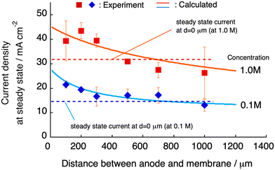 |
| | Fig. 7 Current density at steady state as a function of the distance (d) between the anode and polyelectrolyte membrane using an aqueous solution of CuSO4 with concentrations of 0.1 (blue diamonds) and 1.0 M (red squares). The curves (solid lines) calculated using eqn (4) for infinite t are also displayed and are in good agreement with the experimental data. | |
Although the present study focuses on the deposition of copper, the SED process could be applied to other metals such as Ni, Sn, Au and Ag, in which the deposition rate and current efficiency depend on metallic species and experimental conditions. Since these metals and others including Zn, Co, Fe, Pb, etc. and their alloys are important for industrial manufacturing, electrodeposition of these metals and alloys in the SED system is in progress and the results will be published elsewhere.
Conclusion
We demonstrated an advanced SED system that enables the steady-state current density to be increased by introducing an electrolyte phase between the anode and polyelectrolyte membrane. The ion-transport kinetics during constant-voltage electrodeposition were described based on the experimentally obtained cell constant and a series of two phases: an electrolyte solution with fixed resistivity and a polyelectrolyte membrane with variable resistivity depending on the concentration of copper ions during electrodeposition. The results of the current density at steady state were obtained by numerical analysis based on a theoretical description of the time-dependent concentration changes of the copper ions. These results were compared and, under the present conditions, were in good agreement with those that were experimentally obtained for constant-voltage electrodeposition. The maximum increase in the steady-state current density was attained when the anode was positioned only slightly away from the surface of the polyelectrolyte membrane because of the increase in the ion penetration rate at the solution–membrane interface. This approach proved highly effective for increasing the deposition rate in the SED system. Since the chemical structure and type of ion exchange groups can be crucial for electrodeposition performance in the SED system, design and structural optimization of the chemical structure and control of ion transport characteristics are crucial and currently underway.
Author contributions
S. Y. built the experimental setup and performed the experiments. Y. T. and T. T. performed the experiments and analyzed the data. S. Y. and K. A. performed theoretical analyses. K. A. coordinated the experiments and wrote the paper. All authors discussed the results and contributed to the manuscript.
Conflicts of interest
There are no conflicts of interest to declare.
Acknowledgements
This work was supported by JSPS KAKENHI Grant Number 23H00240.
References
- I. R. Christie and B. P. Cameron, Gold Bull., 1994, 27, 12–20 CrossRef CAS.
- J. Reid, Copper electrodeposition: Principles and Recent Progress, Jpn. J. Appl. Phys., 2001, 40, 2650–2657 CrossRef CAS.
- M. J. Liew, S. Roy and K. Scott, Green Chem., 2003, 5, 376–381 RSC.
- Q. Zhang, Q. Wang, S. Zhang, X. Lu and X. Zhang, ChemPhysChem, 2016, 17, 335–351 CrossRef CAS PubMed.
- I. M. A. Omar, K. M. Emran and M. Aziz, Int. J. Electrochem. Sci., 2021, 16, 150962 CrossRef CAS.
- Y. Zhang, M. An, P. Yang and J. Zhang, Electrocatalysis, 2021, 12, 619–627 CrossRef CAS.
- L. Oniciu and L. Mureşan, J. Appl. Electrochem., 1991, 21, 565–574 CrossRef CAS.
- K. Kondo, T. Matsumoto and K. Watanabe, J. Electrochem. Soc., 2004, 151, C250–C255 CrossRef CAS.
- P. M. Vereecken, R. A. Binstead, H. Deligianni and P. C. Andricacos, IBM J. Res. Dev., 2005, 49, 3–16 CAS.
- M. A. Pasquale, L. M. Gassa and A. J. Arvia, Electrochim. Acta, 2008, 53, 5891–5904 CrossRef CAS.
- L. Jin, J. Q. Yang, F. Z. Yang, D. Zhan, D. Y. Wu and Z. Q. Tian, ACS Sustainable Chem. Eng., 2020, 8, 14274–14279 CrossRef CAS.
- I. M. A. Omar, K. M. Emran, M. Aziza and A. M. Al-Fakiha, RSC Adv., 2020, 10, 32113–32126 RSC.
- T. W. Zeng and S. C. Yen, Int. J. Electrochem. Sci., 2021, 16, 210245 CrossRef CAS.
- X. Liang, X. Ren, R. He, T. Ma and A. Liu, New J. Chem., 2021, 45, 19655–19659 RSC.
- I. C. Oh, H. Y. Kim, S. K. Hyun and Y. M. Byoun, Surf. Interface Anal., 2021, 53, 1035–1042 CrossRef CAS.
- T. M. Braun, J. John, N. Jayaraju, D. Josell and T. P. Moffat, J. Electrochem. Soc., 2022, 169, 012502 CrossRef CAS.
- C. Ramírez, B. Bozzini and J. A. Calderón, Electrochim. Acta, 2022, 425, 140654 CrossRef.
- B. Subramanian, C. Sanjeeviraja and M. Jayachandran, J. Cryst. Growth, 2002, 234, 421–426 CrossRef CAS.
- Z. Jiang, X. Liu, G. Li, Q. Jiang and J. Lian, Appl. Phys. Lett., 2006, 88, 143115 CrossRef.
- X. Pengyuan, X. Shen and G. Xin, Mater. Res. Express, 2021, 8, 026406 CrossRef.
- P. Bhatnagar and M. L. Free, Surf. Coat. Technol., 2006, 200, 6083–6087 CrossRef CAS.
- G. Ercolano, C. Nisselroy, T. Merle, J. Vörös, D. Momotenko, W. W. Koelmans and T. Zambelli, Micromachines, 2019, 11, 6 CrossRef PubMed.
- G. Ercolano, T. Zambelli, C. Nisselroy, D. Momotenko, J. Vörös, T. Merle and W. W. Koelmans, Adv. Eng. Mater., 2020, 22, 1900961 CrossRef CAS.
- J. Hengsteler, B. Mandal, C. Nisselroy, G. P. S. Lau, T. Schlotter, T. Zambelli and D. Momotenko, Nano Lett., 2021, 21, 9093–9101 CrossRef CAS PubMed.
- Y. Wang, X. Xiong, B. F. Ju and Y. L. Chen, Int. J. Mach. Tools Manuf., 2022, 174, 103850 CrossRef.
- K. Akamatsu, S. Nakano, K. Kimura, Y. Takashima, T. Tsuruoka, H. Nawafune, Y. Sato, J. Murai and H. Yanagimoto, ACS Appl. Mater. Interfaces, 2021, 13(11), 13896–13906 CrossRef CAS PubMed.
-
N. Kumar, Comprehensive Physics XII, 2004, ch. 5 Search PubMed.
|
| This journal is © The Royal Society of Chemistry 2024 |
Click here to see how this site uses Cookies. View our privacy policy here.  Open Access Article
 ,
Takaaki
Tsuruoka
 and
Kensuke
Akamatsu
 *
*


