 Open Access Article
Creative Commons Attribution 3.0 Unported Licence
Light-driven interfaces for PFAS detection and destruction
Frank R. A.
Schrama
,
Scott E.
Massimi
,
Michael R.
Dooley
 ,
Brian G.
Trewyn
 *,
Shubham
Vyas
* and
Ryan M.
Richards
 *
*
Department of Chemistry, Colorado School of Mines, Golden, CO 80401, USA. E-mail: btrewyn@mines.edu; svyas@mines.edu; rrichard@mines.edu
First published on 5th July 2024
Abstract
Due to exposure risks and health concerns, global limitations on per- and polyfluoroalkyl substances (PFAS) have become increasingly restrictive over the last few years, with limitations of some legacy PFAS in drinking water reaching single digit ppt in the United States and certain European countries. As the allotted maxima for contamination have reached such low levels, broad research efforts in the degradation and detection of PFAS materials are being intensely investigated. Light driven technologies (photocatalysis and plasmonics) represent important interfacial phenomena with potential to detect and/or decompose PFAS. Despite the commonalities at the interface, little discussion merging detection and destruction exists, thereby resulting in minimal transference of concepts, experimental success, and potential dual functionality systems. This review will cover the basics of photocatalytic degradation technologies surrounding PFAS, the basics of plasmonics for PFAS detection, and a discussion on how these fields can progress in future work.
1. Introduction
As scrutiny on the release of per- and polyfluoroalkyl substances (PFAS) into the environment and contamination of all environmental matrices has increased over the years, so too have the breadth of technologies being investigated to mitigate, capture, and/or destroy PFAS pollutants.1,2 This increased scrutiny is due to the numerous adverse health impacts associated with PFAS exposure including several forms of cancer and connections to birth defects.3–8 This negative impact on health is partially due to the long half-life of PFAS within the human body, and the half-life of PFAS under oceanic conditions is around 250 years, thus, the longevity of these pollutants is significant for future generations.9 Preventative technologies that have been investigated so far include electrochemical oxidation, plasma treatment, oxidative and reductive photocatalysis, sonolysis, supercritical water oxidation, hydrothermal alkaline treatment and thermal degradation.1PFAS materials are known for their unique chemical features, namely their hydrophobic and oleophobic nature, high stability in ambient environments, and resistance to degradation via oxidation and reduction pathways. These features result in a material which offers many utilitarian advantages as a protective or preventative layer that has been used in paints, non-stick cookware, cleaning products, fire-resistant and fire dousing materials, and many more.10–12 While the uses of PFAS have been ongoing for over half a century,13 the harmful effects of these materials have only been investigated in recent times. Legacy PFAS, such as perfluorooctanoic acid (PFOA) and perfluorooctanesulfonic acid (PFOS), have been deemed toxic and pervasive within the human body, causing them to be phased out of production over the years.
While it is generally the unique properties of PFAS that make them difficult to remove from the environment, researchers are attempting to exploit these same properties to help remove these materials from our environment. For example, as PFAS molecules have a hydrophilic head group and a hydrophobic tail, they tend to aggregate onto interfaces. Materials have been designed to take advantage of this behaviour, for example the capture of PFAS onto granular activated carbon or via foam fractionation techniques.14,15 By designing materials that PFAS readily adsorb to and which serve a specific function, such as materials that can degrade recalcitrant materials near their surface, additional optimization via leveraging the nature of PFAS can be achieved. Finally, intelligent material design can go one step further by creating materials that are able to adsorb and interact with PFAS yet require little energetic input, such as the light interacting materials presented in this review.
A recent review summarized the types of PFAS degradation strategies prevalent in the literature as seen in Fig. 1.16 Technologies based on light, such as photocatalysis for PFAS destruction, are promising due to their unique benefits, such as having relatively low energy consumption compared to thermal treatments, end-products that are typically less- or non-harmful, the ability to target multiple pollutants in wastewater, the capability to be used in both aqueous and gaseous phases, and typical mild reaction condition requirements with reasonable reaction kinetics, to mention a few.17 With significant advancements in UV-light treatment technology, commonly employed in water treatment plants for organic pollutant removal, photocatalytic degradation methods could leverage existing infrastructure, leading to simpler implementations compared to some other methods.18
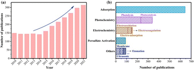 | ||
| Fig. 1 A notable increase in PFAS destruction and removal technologies can be seen in the last decade. A large portion of these is associated with photolysis and photocatalysis.16 | ||
Due to the increased concerns of PFAS toxicity in recent years, the suggested PFAS concentration levels in drinking water have decreased significantly (for example, PFOA limits have been set as low as 4 ppt in April 2024).19,20 As a result, there is an urgent need to develop detection methods capable of measuring PFAS at these extremely low concentrations that can be utilized on-site at water treatment plants with rapid response times. While the traditional methods such as liquid chromatography mass spectrometry (LC-MS) can reach low concentration limits of quantification (LOQ), the low mobility and long run-times of the said methods in addition to the initial cost of instrumentation are often inefficient for testing of water at treatment plants on a national scale.
A different light-driven technology which has gained increased traction is plasmonic driven photo-detectors for bio(chemical) systems.21–24 These detectors have increased mobility for portable, on-site testing applications, offer quick response times, and have demonstrated significant improvement over the last decade in the LOQ concentrations they can achieve.25 Alternatively, efforts are also ongoing for PFAS detection via electrochemistry based sensing approaches. However, significant research is still needed to improve the sensitivity and selectivity of such methods.26–28
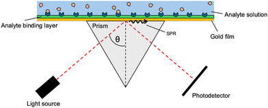
In recent decades, the technology of plasmonic sensors has been advanced via the addition of optical fibres, used to improve the spatial resolution and detection limits.29,30 The use of plasmonic sensors is based on the property that all materials have a unique diffraction angle when hit with an incident light source. A surface layer of pre-defined receptors is designed and deposited on a gold (Au) film, which will have a specific angle of incidence as light reflects off the surface. If the specific binding sites on top of the gold surface bind to the analyte, the overall system changes, resulting in the specific angle of reflection to shift. The appearance of this shift indicates the presence of the analyte, and as the technology improves, the extent of the shift can be correlated to the concentration of the analyte (Fig. 2).31
In terms of degradation, there have been many recent developments in photocatalytic materials capable of destroying PFAS. These materials come in a wide variety and are able to trap PFAS in a reactive environment after the target binds to the surface and the material is excited. These materials are a promising direction for degradation efforts.
In this review, we strive to provide an overview of the two predominant light-driven technologies utilized in the decomposition and detection of PFAS materials, namely semiconductor photocatalysts for degradation and plasmonic photo-sensors for the detection of PFAS. This review aims to discuss these topics under the lens of the surface functionality that can be utilized for PFAS. As this review focusses on photocatalysis and plasmonic materials due to their similar light interactions, other pertinent light-based detection methods, such as fluorescence,32 Raman and resonance scattering,33 and UV-detection,34 can be found in the respective review papers provided.
2. Plasmonic materials
Plasmonic materials, also sometimes termed nanoplasmonics, are sensitive to the frequencies of the IR and visible light spectra when irradiated along the dielectric surface. Surface plasmonic materials have found utility in a variety of environmental remediation technologies. Due to the capabilities of plasmonic materials to act as hot electron generators, they have demonstrated application in near-surface heat transfer, enhancements for absorbers, emitters, and reflectors, and enhancement for photocatalytic processes, as well as other technologies.35 Included in these are the detection and destruction of environmental pollutants, including recalcitrant organics.36,37 A large focus of the work done on plasmonic materials with respect to PFAS surrounds specific PFAS detection at ultra-low concentrations.Recently, the United States Environmental Protection Agency (USEPA) implemented a regulation concerning the maximum contamination level of PFOA and PFOS to be 4 ppt in drinking water with other countries setting lower limits (e.g. Denmark setting the limit for certain PFAS to 2 ppt).38 In an effort to achieve sufficient PFAS detection, one potential solution is the use of plasmonic sensors. In general, plasmonic sensors work via measuring the angle of incident light at which surface plasmon resonance (SPR) occurs by measuring a decrease in reflected light intensity. As the analyte binds to the reflective material (typically gold), the specific angle at which SPR occurs shifts and this shift is noted as the presence of the analyte. A more detailed description of this effect is discussed in section 2.2 SPR fibre-optic sensors. As plasmonic detectors become more mobile, analyte specific, and become easier to use, their potential use for on-site testing of toxic PFAS substances becomes more possible.
2.1 Light interactions with plasmonic materials
Plasmonic materials function via the generation of plasmons, which are the collective oscillations of the free electron cloud activated via light. Plasmons can be considered as bosonic quasiparticle excitations. Bosonic quasiparticles refer to the fact that while individual electrons act as fermions (clear separation between each particle), the synchronous oscillation of the electron cloud can be considered to act as if it were one particle (quasiparticle), with the components free to stack upon themselves (bosonic). Within the bulk of plasmonic materials, the generation of plasmons occurs via a direct electron beam; however, excitation via electromagnetic radiation or light is not allowed. This is due to the energy dispersion curves of photons and plasmons not crossing when in bulk. On the surface of these materials however there can exist an electromagnetic radiation driven excitation of the free electron cloud, resulting in the displacement of the free electron cloud with respect to the stationary positive ion lattice. This excitation results in propagating surface plasmon polaritons (PSPPs) which propagate across along with the light wave (Fig. 3).39,40 | ||
| Fig. 3 A simplified diagram of PSPPs (left) and LSPs (right) when light interacts with either the surface of a bulk metal or nanoparticles. This figure was created by the authors. | ||
In certain cases, metallic nanoparticles (NPs) such as gold can induce a type of surface plasmon different than the PSPPs. If the total size of the NPs is similar to that of the skin-depth surface, (ergo before a significant bulk-depth is reached), and the NP size is significantly smaller than the wavelength of the incident light, the NPs can generate plasmons throughout the whole volume of the material.39 Due to the entire volume of the particle participating in the generation of the plasmon, no propagation is able to take place within the material resulting in localized surface plasmons (LSPs) or localized surface plasmon resonance (LSPR). As the generated plasmons involve the whole of the particles, a dipole is formed over the entire material of stationary positive ions and the oscillating free electron cloud, which collectively act as a mass–spring harmonic oscillator. If the incident light wave is of a wavelength which is in resonance with the oscillation of the electron cloud, the LSP can be formed. The generated plasmon system is also known as a surface plasmon resonance (SPR) system. Once the plasmon is generated within the NP, electron relaxation occurs via multiple pathways. The predominant pathway of energy loss is via intraband transitions. In the example of gold NPs, which have been extensively researched as plasmonic materials due to their relatively facile plasmon generation ability combined with chemical stability, the energy loss of the LSP occurs mainly through the intraband excitation of 5d orbital electrons into the unoccupied 6s–p orbitals, generating electron–hole pairs.39 This energy loss from the LSP eventually dissipates as heat, resulting in highly condensed regions of intense heat that have been studied as pollutant degradation technologies via thermal dispersion and via the generation of hot electrons (Fig. 4).36,40,41
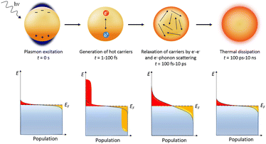 | ||
| Fig. 4 Plasmon induced hot hole generation resulting in thermal dissipation with time frames.40 | ||
2.2 SPR fibre-optic sensors
In a SPR system, there exists an angle of the incident light where the light wave vector is in resonance with the dielectric/metal surface plasmons, which is known as the SPR angle (θSPR). The PSPP on the surface is very sensitive to the dielectric properties of the system, enabling sensory detection methods. These detection methods are angular-modulated, wavelength-modulated, or intensity-modulated, with angular-modulated systems being the most common and sensitive. In the angular-modulated system, a monochromatic beam of light is directed towards the dielectric/surface interface with the angle of incidence changing over time. Any changes to the dielectric/surface interface will result in a shift in the θSPR, noted as a shift in the wavelength at which reflected light intensity drops.37A simple modification to the metal can be used to allow detection of specific materials. By attaching binding sites for the target analyte onto the opposite end of the metal surface (see Fig. 5(a)), a shift in the characteristic θSPR can be seen, as shown in Fig. 5(b). As the analyte of interest is introduced into the system, the binding sites become increasingly occupied, causing a further shift in the θSPR until reaching a binding–unbinding equivalence point for the corresponding analyte concentration (see Fig. 5(c)). Using this binder–analyte property, low concentrations of analyte can be measured within complex matrices. The main concern for θSPR analysis is non-analyte molecules causing false positives by attaching to binding sites.
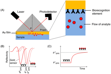 | ||
| Fig. 5 Example of SPR sensing technology. As the analyte binds onto the sensor's surface (a), a shift in the incident angle for SPR is noted (b), indicating that the analyte is present. As more analyte binds, the change in angle levels off (c).37 This figure has been modified from its original publication. | ||
In the literature, the SPR technology used for PFAS is mainly focused on probing. As the allowed concentration of PFAS is set on the scale of a few parts per trillion, a surge of analytical techniques has appeared to meet the low LOQ required for sufficient testing. The current state-of-the-art technologies for ultra-low PFAS concentrations are LC-MS and gas chromatography-mass spectroscopy (GC-MS), with other techniques currently investigated including capillary zone electrophoresis (CZE), colorimetric sensors, fluorous membrane-based ion-selective electrodes, fluorescence-based sensors, electrochemical impedance spectroscopy (EIS), impedance sensors, and ion-transfer stripping voltammetry.25 These techniques all require expensive equipment and are often non-portable, require high levels of user training, and are time consuming in both the instrumental analysis and the analyte preparation.25
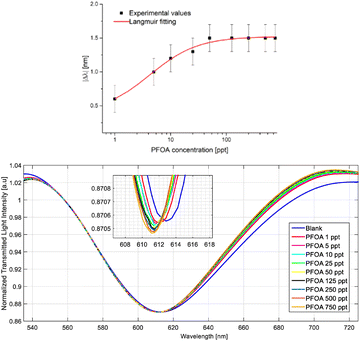
SPR-based sensing technologies aim to circumvent these challenges while still providing an accurate detection method for ppt levels of PFAS concentrations. A limitation of SPR-POFs (plastic optical fibres) is that SPR surface binding to the analyte has used bioreceptors, resulting in the detection of low concentrations (LOD-limit of detection around 0.2 ppb), but not ultra-low concentrations. Recently, attempts have been made to improve on the SPR system by replacing the bioreceptors on the SPR-POF system with molecular imprinted polymers (MIPs), specifically targeting PFOA.25 MIPs have similar selectivity and specificity as bioreceptors while being more stable and having more facile production steps. The authors showed that MIP addition lowered the LOD to 0.81 ppt, which falls within the extreme low concentrations required for legacy PFAS limits. Their testing included an analysis of a simulated sea water matrix which was spiked with known amounts of PFOA. The results shown in Fig. 6 indicated that the SPR-MIP sensor setup was able to detect small changes in PFOA concentration within a more complex matrix, with a notable shift in the SPR angle θSPR with each subsequent increase in PFOA concentration.
As a measure of responsivity for the SPR-MIP sensor, the authors used a Langmuir fitting of the change in the observed wavelength (Δλ nm) compared to the PFOA concentration at the ppt level and noted that compared to the Langmuir fitting of the sensor in Milli-Q water, the performance was reduced when placed in a more complex matrix. The authors attributed this decrease in performance to the chloride anions in the seawater matrix binding to the vinylbenzyl trimethylammonium chloride monomers within the MIP, where an equilibrium state is reached between PFOA and the chloride anions. This competition results in lower sensitivity in the probe readings.
2.3 Plasmonic devices for light driven PFAS degradation
Plasmonic devices have been used in a variety of technologies including the degradation of organic pollutants, catalysis via direct electron transfer, sensing, and others.25,36,40–42 Due to the generation of highly energetic hot carriers within the plasmonic system, potential degradation pathways are made possible. For example, generated hot electrons within plasmonic systems are theoretically able to undergo a similar photo-oxidative degradation mechanism to that of other photocatalysts mentioned earlier.More research is required in the field of plasmonic-driven degradation of PFAS materials to determine the optimal parameters, whether the system should be designed as an oxidative photocatalyst, a photoelectrochemical system, or a reductive photocatalyst via generated ‘hot-holes’. Fig. 7(a) and (b) show two depictions of surface plasmon induced photocatalysis. In Fig. 7(a), the gold nanoparticle acts as both an electron generator via SPR and an electron sink for the titanium dioxide (TiO2) exciton, which is then able to perform reduction processes, while Fig. 7(b) shows an autonomous solar water-splitting device where the majority of generated electrons come from gold nanoparticles undergoing LSPs via light-driven excitation.35
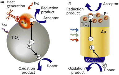 | ||
| Fig. 7 Examples of non-sensor based plasmonic technologies. (a) Plasmonic gold (Au) nanoparticle acts as an electron sink for excited semiconductor electrons as well as an independent electron generator for a more efficient photoactive catalyst. (b) A collection of gold nanoparticles excited via light generates SPR electrons which are then used within the electrochemical cell.35 | ||
With any technology, certain challenges need to be recognized and addressed to improve the field. In the current literature, the main factors which can limit the effectiveness of plasmonic based systems are efficient light absorption, effective and specific surface adsorption for potential analyte destruction, and the ability to generate hot electrons.36
Work done in the field of plasmonic catalysis is widespread. A previous study showed that via a facile impregnation route, Au nanoparticles (NPs) could be integrated into a TiO2 anatase and P25 crystal phase. This integration of gold resulted in an anisotropic flow of SPR generated hot electrons from gold NPs within the crystal structure to the edge of the overall TiO2 crystal, resulting in easily accessible electrons for further reaction and increased recombination times due to the separation of holes and electrons.43
More current work in the field shows advancements of plasmonic catalysis for a variety of uses. Recently, it has been demonstrated that a plasmonic nanohybrid system enabled the hydrogen evolution reaction in which plasmonic generated hot electrons would transfer into the nanohybrid system's ligands and facilitate the concerted proton-electron transfer step and promote hydrogen formation.44
A recent investigation across multiple studies aimed to elucidate the effect of LSPR generated hot electrons on CO2 methanation. These studies found that via the modification of Ag-doped Ni catalysts,45 Au-doped Ni catalysts,46 and TiN-doped Ni catalysts,47 the generated hot electrons from the plasmonic active materials (Ag, Au, TiN) were able to improve the CO2 methanation conversion. One recent paper partially ascribes the increased efficiency for the CO2 methanation via Ni to the hot electrons increasing the Ni surface charge, resulting in more strongly bound CO (a competing end-product for the methanation reaction), and as such lowering the amount of CO products to be removed from the Ni surface before full completion of the CH4 production.47
As shown, plasmonic catalysts have been shown to be of use in a variety of catalytic processes. Investigations into the potential uses of plasmonic materials for PFAS degradation via photocatalytic means (discussed in section 3 Photocatalytic degradation of PFAS) could be a worthwhile venture into increasing photocatalytic efficiency.
3. Photocatalytic degradation of PFAS
3.1 Photocatalytic activation
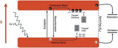
A photocatalyst is a type of catalyst which is excited when irradiated by light of a higher energy than the band gap of the material. An electron (e−) within the catalyst absorbs the energy from the photon and is excited from the valence band to the conduction band. This generates an excited electron within the conduction band (ecb−) and leaves behind a positive hole in the valence band (hvb+). The generated charge carriers are then able to drive redox reactions, with electrons driving reduction reactions and holes driving oxidation reactions. However, there are often competing processes that either prevent the desired reactions from taking place or change the reactivity of the excitons. The first of these processes is recombination, or when the excited electron returns to the conduction band, losing the absorbed energy typically through heat or light, and refills the hole. Recombination is generally not desired, and the recombination rate is a good indicator of the efficiency of a photocatalyst. Another process that can occur is referred to as trapping, in which the excited charge carriers are “trapped” in an energy state between the valence band and the conduction band. The middling energy state slows down the process of recombination, allowing more time for charge carriers to perform redox reactions. In titanium dioxide, defects such as oxygen vacancies provide excellent electron traps, and while these trapped electrons are generally less reactive, the holes that would otherwise be quenched by the trapped electrons are more likely to participate in oxidation reactions. The descriptions below for the most common and state-of-the-art photocatalytic driven processes are summarized in a previous review.16 For further in-depth analysis of the mechanistic and kinetic overview of photocatalytic interactions for PFAS materials, the authors advise reading this article (Fig. 8).3.2 Photo-oxidative degradation of PFCA via heterogeneous catalysts
Various mechanistic routes are proposed in the literature as to the actual degradation mechanism of perfluoroalkyl carboxylic acid (PFCA) in water via the photo-generated hole (hvb+) under UV light. The consensus on the mechanism involves the generated hole abstracting an electron from its surroundings forming a radical species. The competing mechanisms are for the hvb+ to either abstract the electron from hydroxyl anions (HO−) in solution, producing hydroxyl radicals (HO˙), or the hvb+ abstracts an electron from the PFAS head group, taking PFCA (CnF2n+1COO−) as an example, and generates a PFCA radical (CnF2n+1COO˙). In the case of hydroxyl radical formation, the radical attacks the acid head group, abstracting the hydrogen and transferring the radical species onto the carbonyl group, generating the PFCA radical.48 However, such H-atom abstraction requires the headgroup of the PFCA to be protonated which is unlikely in the aqueous phase near neutral pH since the pKa of PFCA is known to be very low. A surface coordination of PFCA however may cause the polar headgroup to be protonated. Nonetheless, of the two options, the experimental observations indicate that PFCA coordination onto the surface is the more influential pathway. This is due to an observed dependence on the PFCA chain length, which has been attributed to shorter chains being unable to adsorb onto the catalytic surface. As a result, the longer PFCA is degraded more quickly, and hence there is a chain length dependence in such degradation approaches.49,50 Meanwhile, the hydroxyl radical flows freely through solution and has no such restriction based on chain length due to adsorption. Once the PFCA radical is formed, a variety of degradation pathways are proposed with the common result being a loss of one CF2 group from the carbon chain length, producing CO2 and HF as the end products. The resulting shorter chain PFCA (Cn−1F2n−1COO−/Cn−1F2n−1COOH) then undergoes the degradation cycle again, removing a CF2 group each time. Fig. 9 shows the proposed degradation mechanisms via the radical formation.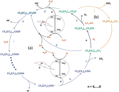 | ||
| Fig. 9 Diagram of potential PFCA degradation pathways via radical generation. Photo-redox pathway (blue arrows (a)) and β-scission pathway (orange arrows (b)).52 This image has been modified from its original publication. | ||
Regardless of the mechanism involved, the overall lifetime of photoexcited holes is crucial. A longer hole lifetime enhances the catalyst's ability to directly oxidize PFCA or water, thereby initiating the degradation mechanism. Therefore, improvements in photocatalysis, such as more efficient charge separation leading to prolonged hole lifetimes, are likely to enhance PFCA degradation.
When discussing PFCA degradation, it is important to note that chain shortening or other carbon–carbon bond breaking is insufficient for PFCA destruction, as those will result in PFCA with a shorter chain length. These shortened PFCA molecules are similarly detrimental to health and the environment but harder to detect and destroy. For true PFCA and other PFAS degradation, the carbon–fluorine bonds must be broken. This is one of the advantages of reduction over oxidation (section 3.3 Photo-reductive degradation of PFAS). Reduction pathways typically directly attack the carbon–fluorine bonds while oxidation pathways are chain shortening. Complete oxidation and mineralization are required for the desired result of complete PFAS destruction.51
Anatase TiO2 has been studied for over a decade as a potential photocatalyst for PFCA degradation with little success. TiO2 has been found to degrade PFCAs through charge transfer mediated oxidation as described above.16,52,54–57 The main challenges regarding TiO2 semiconductors are the short lifetime of the photogenerated exciton as well as the difficulty of oxidizing PFCAs with hydroxyl radicals at moderate pH values, the main reactive species generated from titania. Various methods of improving the exciton lifetime, and by extension photocatalytic capabilities, have been investigated via anatase TiO2 compared to the baseline of P25 (P25 is a 3![[thin space (1/6-em)]](https://www.rsc.org/images/entities/char_2009.gif) :
:![[thin space (1/6-em)]](https://www.rsc.org/images/entities/char_2009.gif) 1 ratio of the anatase to rutile phase), a combined phase of TiO2. These improvements include nanostructured carbon supports, transition metal doping, and the formation of heterojunctions with other semiconductors.16,57
1 ratio of the anatase to rutile phase), a combined phase of TiO2. These improvements include nanostructured carbon supports, transition metal doping, and the formation of heterojunctions with other semiconductors.16,57
A study recently demonstrated that by adding noble metal nanoparticles to titania, the PFOA decomposition rate can be greatly increased. Silver, palladium, and platinum nanoparticles were deposited onto commercial P25 titania and the resultant photocatalytic properties were tested. The measured rate constants were up to 12.5 times higher in the case of the platinum modified nanoparticles than for the native P25. The increased reactivity was attributed to the metal nanoparticles acting as an electron sink, which increased the lifetimes of the exciton and, specifically, the holes, which participate in the decomposition. The authors also concluded that the catalysts became more effective as the work functions of the doped metals increased. This is because as the work function of the nanoparticle increases, the potential difference between the metal and the TiO2 increases, allowing electrons to transfer from the TiO2 to the metal faster.58 This method of increasing decomposition is similar to the effect of adding electron scavengers to the reaction. Removing excess electrons from the catalyst will decrease recombination rates and make the photocatalyst more active. The addition of noble metal nanoparticles to TiO2 allows for a similar effect that electron scavengers provide, without the need to add additional chemicals to the reaction, which could be undesirable when attempting to clean ground or drinking water.
One of the most successful examples of PFOA degradation with titanium dioxide was shown in a study by Wong and coworkers. A composite material of TiO2 and boron nitride (BN) was made through a simple calcination procedure. This material was found to act as a type-II heterojunction semiconductor. This TiO2–BN heterojunction yields a high concentration of holes on the BN with few electrons to recombine with, increasing recombination times and therefore overall efficiency of the exciton generation.59 Further discussion of the effectiveness of BN photocatalysis for PFCA degradation can be found in section 3.2.4 Boron nitride. The use of carbon supports has been shown to improve TiO2 photocatalytic degradation capabilities; however, the nature of the effect is disputed. While most reports agree that carbon support systems (such as graphene and carbon nanotubes) provide a route for the generated ecb− to ‘escape’ the exciton due to the conductive nature of the carbon support, other studies argue that the role of carbon is not related to its conductive properties but rather to its hydrophobic properties. The effect other hydrophobic supports had on the measured PFOA degradation by UV/TiO2 photocatalysts was recently examined.60 This work found that polytetrafluoroethylene (PTFE), polyethylene (PE), and graphene oxide (GO) all resulted in similar levels of PFOA degradation despite PTFE and PE being non-conductive. The authors postulated that rather than an electronic effect occurring via the nanostructured carbon supports, the hydrophobic nature of the carbon created zones of dehydration on the titania surface. These zones allowed for direct adsorption of PFCA to the titania surface and therefore facilitated faster charge transfer, as depicted in Fig. 10.
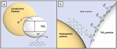 | ||
| Fig. 10 Schematic depicting the hypothesized interaction between the hydrophobic graphene support and the TiO2 semiconductor for PFOA oxidation.60 | ||
Analogous methods of enhancing the photocatalytic strength of TiO2 have been investigated for In2O3. Carbon materials have been found to increase the photocatalytic activity of In2O3, where they are believed to act as transport materials for electrons, although it is possible that they act as hydrophobic supports as discussed within section 3.2.1 Titanium dioxide. The formation of heterojunctions has also been investigated, where the heterojunction allows for either the hvb+ or ecb− to be transported away resulting in an increase in exciton lifetime.61 An example of this heterojunction is a recent effort that doped In into carbon-supported titanite nanotubes. This composite material showed 99% efficiency in PFOA degradation under optimal conditions.62 The researchers attribute the success to the heterojunction, which facilitates electron transfer and stepwise defluorination, achieving ∼60% defluorination after only 4 hours.
As previously mentioned, the addition of BN to TiO2 was also found to improve photocatalytic activity via the formation of a type-II heterojunction. A type-II heterojunction means that the band gaps of the conjoined materials have an overlap, which allows excited electrons to go from the lower energy band gap into the higher energy band gap to prevent recombination. The defect sites in BN act as a secondary conduction band, with a much lower band gap than BN has natively. However, even with defect sites, the BN has a band gap that is considerably higher than other semiconductors such as TiO2. This is evident by the fact that BN can be excited under higher energy ultraviolet C radiation (254 nm) but not ultraviolet A (365 nm). The benefit that the composite heterojunction provides is in irradiating with UV-C, electrons are excited in both materials and are then transferred to the lower energy conduction band of TiO2, whereas the holes are transferred to the higher energy valence band of the BN. This yields a high concentration of holes on the BN with few electrons to recombine with.59
In a later study, it was found that BN is a superior active site for oxidation of PFCAs due to its high hydrophobicity, which promotes PFCA adsorption and prevents formation of hydroxyl radicals, which are less effective at oxidizing PFOA.66
3.3 Photo-reductive degradation of PFAS
In contrast to the oxidative processes described above, photo-reductive pathways for PFAS materials involve the generation of reducing radicals via an activation source such as UV light and reducing compounds such as sulfites and sulfides.16,68 These reducing radicals mainly occur as either hydrated electrons (eaq−) and hydrogen atoms (H˙), with side-products from reducing agents occurring as well (SO3˙− in the case of sulfite). The hydrated electron is the most studied reducing radical due to its strong reducing power and is found to cleave the PFAS molecule at the α-CF bond. This cleavage can occur due to the reduction potential of the C–F bond (E < −2.7 V) being lower than that of the eaq− (E = −2.9). Once the α-site cleavage is instigated, cyclic stepwise degradation of the PFAS molecule occurs as shown in Fig. 11. Unlike the oxidative degradation pathways where the polar headgroup loses an electron, the reductive degradation mechanisms are shown to be more complicated. A recent study showed that the defluorination due to the reactivity of PFAS with a hydrated electron depends on the polar head group.69 In the case of carboxylates, the defluorination occurs at the alpha-carbon (the carbon next to the carboxylic acid), whereas the defluorination occurs at the middle of the perfluoroalkyl chain in the case of the sulfonate head group. This mechanistic computational study aligns well with the known observed rate constants of PFAS with hydrated electrons in constant irradiation experiments in the aqueous phase.70–73 Series of other studies also demonstrated the use of C–F bond dissociation energies as a marker to probe the feasibility of reductive degradation of PFAS. The defluorination event is followed by H/F exchange as shown in Fig. 11. Molecular mechanisms involved in reductive degradation of PFAS are less established when compared to the oxidative degradation pathways. Nevertheless, since the reduction of PFAS is energetically more feasible when compared to oxidation, chemical reduction is a more attractive technique. In terms of scaling up of photocatalytic reductive degradation approaches for PFAS, one must pay attention to the co-constituents which can also act as non-target scavengers of hydrated electrons as demonstrated by a recent study.74,75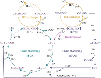 | ||
| Fig. 11 Proposed cyclic pathways of PFOA and PFOS degradation via aqueous electrons. Numbers in parentheses (e.g. (26), (31), etc.) correspond to equations within the original paper.16 | ||
4. Future outlooks
4.1 Hydroxyl radical and TiO2 debate
Within the PFAS photocatalyst literature, there is an ongoing discussion on the effectiveness of the TiO2 material as a photocatalyst for oxidative degradation of PFAS, typically targeting PFOA. A paper by Li et al. compared the performance of TiO2 to that of In2O3 for PFOA degradation via UV-light irradiation.56 The paper claims that TiO2 decomposes PFOA by generating hydroxyl radicals which in turn react with PFOA, and that the interaction between HO˙ and PFOA is not favourable. The paper goes on to claim that In2O3 is able to perform direct radicalization of PFOA via favourable surface interactions, and showed that In2O3 degrades approximately 5 times more PFOA than TiO2 after 4 hours of irradiation under 254 nm UV light (80% and 15.9%, respectively).56A paper by Javed et al. attempted to show the effectiveness of HO˙ for PFOA degradation.76 In the study, the authors use H2O2 irradiated with UV light to form HO˙ to act as the oxidizing agent. The authors concluded that compared to photolysis, the process of PFOA degradation via direct UV irradiation, the UV + H2O2 system showed no enhancement and that at higher concentrations, it hampered PFOA degradation.76
Bouteh et al. analysed the impact of graphene oxide (GO) supports on TiO2 and its photocatalytic degradation of PFCA including PFOA. The authors determined that due to binding of hydroxyl groups onto the TiO2 surface, the ability to bind PFCA close enough for direct photooxidative reactions was hampered. Contrary to some published reports, which state that GO supports increase the lifespan of generated excitons by creating pathways for generated electrons, the authors compared other non-conductive hydrophobic supports and concluded that the hydrophobicity of the GO is the defining factor in improving the TiO2 activity. The paper claims that the hydrophobic supports are able to retain PFAS near the surface of TiO2 sufficiently long enough for a photooxidative process to occur and alludes to the low performance of TiO2 photocatalysts.60
Future research involving different support materials that bind more strongly to PFAS is required to elucidate the role of the support. One possibility is measuring the degradation of different length PFCA, because of the chain length dependence of this hydrophobic interaction. If there is a more pronounced chain length dependence with the supporting material, then it is likely that the hydrophobic interaction is the main driving force, and vice versa. Alternatively, it may be possible using advanced surface analysis techniques to examine how PFAS coordinates to the surfaces in these systems.
In the three example publications (vide supra), the photocatalytic activity of TiO2 is viewed as poor, with points of contention including the ineffectiveness of generated HO˙ for degrading PFOA, the slow surface-to-PFOA direct oxidation pathways, and the low binding affinity of PFCAs onto the catalyst surface. Taken in isolation, these papers paint a clear picture that TiO2, typically used in its P25 form, is inefficient at degrading PFAS compounds.
A paper by Fu et al. attempted to categorically compare the commonly tested semiconductors and their ability to degrade PFOA. In this paper, the authors compared Ga2O3, In2O3, CeO2, TiO2, and CdS, with all materials tested under the same PFOA starting concentration, temperature, initial pH, and UV irradiation conditions. The results of the study indicated that the highest impact of effectiveness of PFOA degradation after 10 hours mirrored the size of the semiconductor band gap, resulting in the following ranking from the most to least efficient: Ga2O3 > TiO2 > CeO2 > In2O3 > CdS. Here, the effectiveness of TiO2 was measured to be 84%, while In2O3 was measured to degrade 20% of the initial PFOA.63 These results are nearly in direct opposition of those of Li et al.
An important factor mentioned in both papers is the pH. Li et al. mentioned that at pH < 2, the TiO2 activity for PFOA degradation is increased significantly, with their experiments run under pH conditions of 3.8. One may argue that at pH < 2, some fraction of PFOA will be protonated, thereby undergoing oxidation via electrons in the conduction band as weak as via H-atom abstraction by HO˙. However, Fu et al. ran their experiments with an initial pH of 3.0 ± 0.2, resulting in a much higher activity in the TiO2 semiconductor compared to Li et al. While this is an indicator of the effect of pH on TiO2 photocatalytic activity, it is important to note that these two investigations had other variables in their experimental setup. Fu et al. conducted their experiments with a 32 W low-pressure UV lamp with 254 nm light and a starting PFOA concentration of 50 ng L−1. Li et al. ran their experiments with a 23 W low-pressure UV lamp with 254 nm light and a starting PFOA concentration of 100 μmol L−1, or 41 mg L−1, which is 6 orders of magnitude greater than Fu et al. The reasoning behind this large concentration was to reduce the impact of In2O3 adsorption onto PFOA, reducing activity.
The lack of surface area measurements for complete comparison has been noted in many studies. We believe that by adding this lens to compare various photocatalysts, a more complete picture can be drawn. Until differences in surface areas can be removed as a potential factor in PFAS degradation performance, a conclusive statement on the effectiveness of the said photocatalysts will also be up for debate.
A recent paper by Carre-Burritt et al. attempted to determine the effectiveness of PFCA destruction via generated HO˙ radicals in an aqueous solution using computational methods. They noted that as the reduction potential (E°) of the (HO˙/HO−) couple is around 1.9 V compared to the range of (PFCA˙/PFCA−) E° of 2.2–2.5 V, the ability of the HO˙ radical to oxidize PFCA compounds is unfavoured. At pH 0 however, the E° of (HO˙, H+/H2O) is noted to be around 2.73 V, indicating that hydroxyl radicals generated at lower pH should have a thermodynamically favoured reaction with PFCA compounds. The paper shows that within a range of pH −1.0 to 1.5, their chosen PFCA, perfluorobutanoic acid, was more effectively destroyed at lower pH values and that a significant portion of the degradation occurred via H-abstraction.48
In general, the effectiveness of hydroxyl radicals and by extension TiO2 photocatalysts is less than that of other available photocatalysts. However, the key takeaway we would like to provide is that the efficiency can be increased significantly via low and ultralow pH and thereby would provide a more accurate comparison of P25 activity as a baseline.
4.2 Other post-transition metals as semi-conductor photocatalysts
Ga, In and Bi are three post-transition metals whose oxides are commonly investigated as potential semiconductors for oxidative PFAS degradation. These metals are found in groups 13 and 15. As elements within the same group are often found to have similar chemical activity, it is worth noting that Tl, As, and Sb and their respective oxides are not included in investigations into light driven semiconductor technology for PFAS degradation. While these elements are known to be toxic, their potential uses in PFAS destruction are worthy of further attention particularly as a means to gain deeper fundamental insights. Recent work studying SbO3 supports for a TiO2 photooxidative system was published and showed results of increased PFAS degradation when compared to standalone TiO2. The generated heterojunction of Sb2O3/TiO2 resulted in a removal of 81.83% of initial PFOA compared to the standalone P25 removal of 32.3% and mesoporous TiO2 removal of 55.9% of initial PFOA.574.3 Effect of porosity on PFAS photocatalysis
An underexplored tool for PFAS photodegradation is the use of porous catalysts. One major issue with the use of photocatalysts for PFCA degradation is that the oxidation product is the same PFCA but one chain length shorter. This results in total mineralization becoming more difficult as each shorter chain PFCA is less prone to oxidation. Oxidation becomes more difficult with shorter chains because there is a chain length dependence in PFOA adsorption onto most catalysts. And so as the PFCA has chain lengths removed, it becomes more difficult to adsorb and undergo oxidation. A possible solution to this problem would be to use porous photocatalysts. The effect of the pore would be to keep the oxidized PFCA adsorbed within the pore volume, preventing desorption and bypassing the issue of needing to readsorb. However, there are inherent issues with using a porous photocatalyst. Namely, as a photocatalyst interacts with light primarily on the surface, it becomes difficult for charge carriers to be activated in the bulk, where the majority of the surface area is in a porous material. Yet there are a plurality of effective porous photocatalysts in the literature which are able to take advantage of the drastically increased surface area and mass transfer that the materials provide.77,785. Conclusions
This review covers aspects of the light-driven technologies of photocatalysis and plasmonic processes, concerning both how light enables their effects and how they are used in relation to PFAS. The field of PFAS remediation research is vast however, and many knowledge gaps and future challenges still need to be addressed. Some of these challenges are identified below:- Almost all papers performing initial testing on photocatalytic degradation of PFCA focus on PFOA as their primary PFCA. While the PFOA molecule is known to be toxic, well studied for comparison, and is a known recalcitrant molecule within the PFCA family, some techniques which have shown promise for breaking down PFOA have shown no to little effect on PFOS. As PFOA and PFOS are both legacy PFAS with very low limits of allowed concentrations within drinking water, a more diversified spread of PFAS degradation testing will be beneficiary for narrowing down potential large-scale implementations for effectively breaking down different PFAS molecules.
- While research has compared the photocatalytic capabilities of various materials, no standard baseline has been determined for accurate photocatalytic testing. While LC-MS is typically considered as the most reliable technique, due to the relatively high amount of user training and analyte set-up required, many researchers have sought out other techniques such as F− ion probing. Certain concerns have been raised on potential false-positive readings of other anions within solution, and in porous systems, the F− ions can be trapped within the system and therefore read as false-negatives. Reliable and facile benchtop testing of PFAS degradation would allow for more streamlined comparisons of degradation results.
- When PFAS degradation research is reported, the parameters which are given to determine catalytic effectiveness can vary greatly. When reporting catalytic improvement, authors tend to compare their material to P25, which has been determined with some consensus to be a baseline photocatalyst. However, as P25 will be active only in lower pH ranges, tests run at a higher pH will result in an increase in perceived activity of the new material, as P25 is essentially not able to perform. Not only that, but when comparisons are made, rather than detailing catalyst reaction rates, some papers compare their material to their P25 via percentages and magnitude of activity noted. While such statements can aid in the discussion of improvements found within novel materials, without having a baseline in which P25 is active (ergo a high pH and low pH comparison), any claims made about the relative activity of the novel photocatalyst fall short. Additionally, we believe that an agreement of set parameters, including pH, light intensity, PFAS loading, exposure time, and others, should be established for PFAS photodegradation to ensure that just comparisons can be made throughout the literature.
- Most testing done on both light-driven technologies tends to be conducted under only ideal conditions. Initial testing for advancements being done in a simple solution and under ideal conditions is logical, as it allows for more comprehensive result analysis and comparison to other studies done in the literature. However, by not following up on these tests with more complex matrix analysis, certain capabilities of novel materials may be overstated as their functionality under real-world conditions is not expressed. Real world PFAS contaminated systems will have multiple types of PFAS and can include a wide range of non-PFAS type organic pollutants, as well as other contaminants. Only by adding some rudimentary testing with a more complex matrix can the applications of these materials be judged for environmental remediation.
Data availability
No primary research results, software or code have been included and no new data were generated or analysed as part of this review.Author contributions
F. R. A. S. and S. E. M. wrote the original draft, provided the literature study and formal analysis, and revised the manuscript. B. G. T., S. V. and R. M. R. acquired funding for the project, management, revision of the manuscript and conceptualization. M. R. D. provided analysis and revision of the manuscript.Conflicts of interest
There are no conflicts to declare.Acknowledgements
The authors thank the Army Core of Engineers (Fund number: W912HZ-23-2-0009) for funding this work. The team also acknowledges support from PFAS@Mines.Notes and references
- J. N. Meegoda, B. Bezerra De Souza, M. M. Casarini and J. A. Kewalramani, Int. J. Environ. Res. Public Health, 2022, 19, 16397 CrossRef.
- S. Yadav, I. Ibrar, R. A. Al-Juboori, L. Singh, N. Ganbat, T. Kazwini, E. Karbassiyazdi, A. K. Samal, S. Subbiah and A. Altaee, Chem. Eng. Res. Des., 2022, 182, 667–700 CrossRef CAS.
- M. P. Purdue, J. Rhee, H. Denic-Roberts, K. A. McGlynn, C. Byrne, J. Sampson, J. C. Botelho, A. M. Calafat and J. Rusiecki, Environ. Health Perspect., 2023, 131, 077007 CrossRef CAS PubMed.
- J. Rhee, K. H. Barry, W.-Y. Huang, J. N. Sampson, J. N. Hofmann, D. T. Silverman, A. M. Calafat, J. C. Botelho, K. Kato, M. P. Purdue and S. I. Berndt, Environ. Res., 2023, 228, 115718 CrossRef CAS.
- V. C. Chang, J. Rhee, S. I. Berndt, S. C. Moore, N. D. Freedman, R. R. Jones, D. T. Silverman, G. L. Gierach, J. N. Hofmann and M. P. Purdue, Int. J. Cancer, 2023, 153, 775–782 CrossRef CAS PubMed.
- R. R. Jones, J. M. Madrigal, R. Troisi, H.-M. Surcel, H. Öhman, J. Kivelä, H. Kiviranta, P. Rantakokko, J. Koponen, D. N. Medgyesi, K. A. McGlynn, J. Sampson, P. S. Albert and M. H. Ward, JNCI, J. Natl. Cancer Inst., 2023, djad261 Search PubMed.
- J. T. Szilagyi, V. Avula and R. C. Fry, Curr. Environ. Health Rep., 2020, 7, 222–230 CrossRef CAS.
- C. R. Stein, D. A. Savitz, B. Elston, P. G. Thorpe and S. M. Gilboa, Reprod. Toxicol., 2014, 47, 15–20 CrossRef CAS.
- Y. Li, T. Fletcher, D. Mucs, K. Scott, C. H. Lindh, P. Tallving and K. Jakobsson, Occup. Environ. Med., 2018, 75, 46–51 CrossRef PubMed.
- G. F. Peaslee, J. T. Wilkinson, S. R. McGuinness, M. Tighe, N. Caterisano, S. Lee, A. Gonzales, M. Roddy, S. Mills and K. Mitchell, Environ. Sci. Technol. Lett., 2020, 7, 594–599 CrossRef CAS.
- Wisconsin Department of Health Services, Chemicals: Perfluoroalkyl and Polyfluoroalkyl (PFAS) Substances, https://www.dhs.wisconsin.gov/chemical/pfas.htm, (accessed 31 January 2024).
- Wisconsin Department of Natural Resources, PFAS-Containing Firefighting Foam, https://dnr.wisconsin.gov/topic/PFAS/AFFF.html, (accessed 31 January 2024).
- L. G. T. Gaines, Am. J. Ind. Med., 2023, 66, 353–378 CrossRef CAS PubMed.
- I. Najm, B. Gallagher, N. Vishwanath, N. Blute, A. Gorzalski, A. Feffer and S. Richardson, AWWA Water Sci., 2021, 3, e1245 CrossRef CAS.
- Y. Wang, Y. Ji, V. Tishchenko and Q. Huang, Chemosphere, 2023, 311, 137004 CrossRef CAS PubMed.
- F. Liu, X. Guan and F. Xiao, J. Hazard. Mater., 2022, 439, 129580 CrossRef CAS PubMed.
- K. Kabra, R. Chaudhary and R. L. Sawhney, Ind. Eng. Chem. Res., 2004, 43, 7683–7696 CrossRef CAS.
- A. D. Dotson, C. E. Rodriguez and K. G. Linden, J. AWWA, 2012, 5, E318–324 Search PubMed.
- FACT SHEET PFOA & PFOS Drinking Water Health Advisories, US Environmental Protection Agency, 2016 Search PubMed.
- Biden-Harris Administration Finalizes First-Ever National Drinking Water Standard to Protect 100M People from PFAS Pollution, https://www.epa.gov/newsreleases/biden-harris-administration-finalizes-first-ever-national-drinking-water-standard.
- A. E. Cetin, A. F. Coskun, B. C. Galarreta, M. Huang, D. Herman, A. Ozcan and H. Altug, Light: Sci. Appl., 2014, 3, e122 CrossRef CAS.
- T. Mueller, A. C. Ferrari, F. Koppens, F. Xia and X. Xu, IEEE J. Sel. Top. Quantum Electron., 2014, 20, 0200103 Search PubMed.
- J.-H. Park, Y.-W. Cho and T.-H. Kim, Biosensors, 2022, 12, 180 CrossRef CAS.
- M. Alavirad, S. S. Mousavi, L. Roy and P. Berini, Opt. Express, 2013, 21, 4328 CrossRef CAS PubMed.
- R. Pitruzzella, F. Arcadio, C. Perri, D. Del Prete, G. Porto, L. Zeni and N. Cennamo, Chemosensors, 2023, 11, 211 CrossRef CAS.
- H. B. Lamichhane and D. W. M. Arrigan, Curr. Opin. Electrochem., 2023, 40, 101309 CrossRef CAS.
- R. B. Clark and J. E. Dick, ACS Sens., 2020, 5, 3591–3598 CrossRef CAS PubMed.
- S. P. Sahu, S. Kole, C. G. Arges and M. R. Gartia, ACS Omega, 2022, 7, 5001–5007 CrossRef CAS PubMed.
- G. I. Janith, H. S. Herath, N. Hendeniya, D. Attygalle, D. A. S. Amarasinghe, V. Logeeshan, P. M. T. B. Wickramasinghe and Y. S. Wijayasinghe, J. Pharm. Biomed. Anal. Open, 2023, 2, 100019 CrossRef.
- J. Pollet, F. Delport, K. P. F. Janssen, K. Jans, G. Maes, H. Pfeiffer, M. Wevers and J. Lammertyn, Biosens. Bioelectron., 2009, 25, 864–869 CrossRef CAS PubMed.
- J. Jing, K. Liu, J. Jiang, T. Xu, S. Wang, J. Ma, Z. Zhang, W. Zhang and T. Liu, Photonics Res., 2022, 10, 126 CrossRef CAS.
- R. F. Menger, E. Funk, C. S. Henry and T. Borch, Chem. Eng. J., 2021, 417, 129133 CrossRef CAS PubMed.
- H. Ryu, B. Li, S. De Guise, J. McCutcheon and Y. Lei, J. Hazard. Mater., 2021, 408, 124437 CrossRef CAS PubMed.
- A. U. Rehman, M. Crimi and S. Andreescu, Trends Environ. Anal. Chem., 2023, 37, e00198 CrossRef CAS.
- S. V. Boriskina, H. Ghasemi and G. Chen, Mater. Today, 2013, 16, 375–386 CrossRef CAS.
- M. E. King, C. Wang, M. V. Fonseca Guzman and M. B. Ross, Chem Catal., 2022, 2, 1880–1892 CrossRef CAS.
- C. M. Miyazaki, F. M. Shimizu and M. Ferreira, in Nanocharacterization Techniques, Elsevier, 2017, pp. 183–200 Search PubMed.
- E. Southerland and L. S. Birnbaum, Environ. Sci. Technol., 2023, 57, 7103–7105 CrossRef CAS PubMed.
- V. Amendola, R. Pilot, M. Frasconi, O. M. Maragò and M. A. Iatì, J. Phys.: Condens. Matter, 2017, 29, 203002 CrossRef.
- M. Ahlawat, D. Mittal and V. Govind Rao, Commun. Mater., 2021, 2, 114 CrossRef CAS.
- H. Wei, S. K. Loeb, N. J. Halas and J.-H. Kim, Proc. Natl. Acad. Sci. U. S. A., 2020, 117, 15473–15481 CrossRef CAS PubMed.
- Z. Zhang, C. Zhang, H. Zheng and H. Xu, Acc. Chem. Res., 2019, 52, 2506–2515 CrossRef CAS.
- Z. Bian, T. Tachikawa, P. Zhang, M. Fujitsuka and T. Majima, J. Am. Chem. Soc., 2014, 136, 458–465 CrossRef CAS.
- A. Dey, A. Mendalz, A. Wach, R. B. Vadell, V. R. Silveira, P. M. Leidinger, T. Huthwelker, V. Shtender, Z. Novotny, L. Artiglia and J. Sá, Nat. Commun., 2024, 15, 445 CrossRef CAS.
- I. García-García, E. C. Lovell, R. J. Wong, V. L. Barrio, J. Scott, J. F. Cambra and R. Amal, ACS Sustainable Chem. Eng., 2020, 8, 1879–1887 CrossRef.
- J. N. G. Stanley, I. García-García, T. Perfrement, E. C. Lovell, T. W. Schmidt, J. Scott and R. Amal, Chem. Eng. Sci., 2019, 194, 94–104 CrossRef CAS.
- Y. F. Zhu, B. Xie, J. A. Yuwono, P. Kumar, A. S. Sharma, M. P. Nielsen, A. Bendavid, R. Amal, J. Scott and E. C. Lovell, EES Catal., 2024, 2, 834–849 RSC.
- A. Carre-Burritt, C. Amador and S. Vyas, Aqueous PFCA Destruction by Hydroxyl Radical at Low pH: A Putative H-atom Abstraction Mechanism, ChemRxiv, 2022, preprint, DOI:10.26434/chemrxiv-2022-64bzw.
- Y. Wang, R. Pierce, H. Shi, C. Li and Q. Huang, Environ. Sci.: Water Res. Technol., 2020, 6, 144–152 RSC.
- L. Li, Y. Wang and Q. Huang, ACS ES&T Eng., 2021, 1, 1737–1744 Search PubMed.
- S. C. E. Leung, P. Shukla, D. Chen, E. Eftekhari, H. An, F. Zare, N. Ghasemi, D. Zhang, N.-T. Nguyen and Q. Li, Sci. Total Environ., 2022, 827, 153669 CrossRef CAS PubMed.
- M. Sansotera, F. Persico, V. Rizzi, W. Panzeri, C. Pirola, C. L. Bianchi, A. Mele and W. Navarrini, J. Fluorine Chem., 2015, 179, 159–168 CrossRef CAS.
- J. Schneider, M. Matsuoka, M. Takeuchi, J. Zhang, Y. Horiuchi, M. Anpo and D. W. Bahnemann, Chem. Rev., 2014, 114, 9919–9986 CrossRef CAS.
- S. C. Panchangam, A. Y.-C. Lin, K. L. Shaik and C.-F. Lin, Chemosphere, 2009, 77, 242–248 CrossRef CAS.
- B. Xu, M. B. Ahmed, J. L. Zhou, A. Altaee, M. Wu and G. Xu, Chemosphere, 2017, 189, 717–729 CrossRef CAS.
- X. Li, P. Zhang, L. Jin, T. Shao, Z. Li and J. Cao, Environ. Sci. Technol., 2012, 46, 5528–5534 CrossRef CAS.
- X. Yao, J. Zuo, Y.-J. Wang, N.-N. Song, H.-H. Li and K. Qiu, Front. Chem., 2021, 9, 690520 CrossRef CAS PubMed.
- M. Li, Z. Yu, Q. Liu, L. Sun and W. Huang, Chem. Eng. J., 2016, 286, 232–238 CrossRef CAS.
- L. Duan, B. Wang, K. N. Heck, C. A. Clark, J. Wei, M. Wang, J. Metz, G. Wu, A.-L. Tsai, S. Guo, J. Arredondo, A. D. Mohite, T. P. Senftle, P. Westerhoff, P. Alvarez, X. Wen, Y. Song and M. S. Wong, Chem. Eng. J., 2022, 448, 137735 CrossRef CAS.
- E. Bouteh, M. J. Bentel and E. L. Cates, J. Hazard. Mater., 2023, 453, 131437 CrossRef CAS PubMed.
- J. Paul Guin, J. A. Sullivan and K. R. Thampi, ACS Eng. Au, 2022, 2, 134–150 CrossRef CAS.
- J.-M. Arana Juve, F. Li, Y. Zhu, W. Liu, L. D. M. Ottosen, D. Zhao and Z. Wei, Chemosphere, 2022, 300, 134495 CrossRef CAS PubMed.
- C. Fu, X. Xu, C. Zheng, X. Liu, D. Zhao and W. Qiu, Environ. Geochem. Health, 2022, 44, 2943–2953 CrossRef CAS.
- L. Duan, B. Wang, K. Heck, S. Guo, C. A. Clark, J. Arredondo, M. Wang, T. P. Senftle, P. Westerhoff, X. Wen, Y. Song and M. S. Wong, Environ. Sci. Technol. Lett., 2020, 7, 613–619 CrossRef CAS.
- M. Kim, A. Peeples, H. Estrada, S. Fowler, L. Chiang, J. Morgan, M. Doganay, B. Walls, B. Wang, J. C. Samba and M. S. Wong, in 2021 Waste-management Education Research Conference (WERC), IEEE, Las Cruces, NM, USA, 2021, pp. 1–7 Search PubMed.
- B. Wang, Y. Chen, J. Samba, K. Heck, X. Huang, J. Lee, J. Metz, M. Bhati, J. Fortner, Q. Li, P. Westerhoff, P. Alvarez, T. P. Senftle and M. S. Wong, Chem. Eng. J., 2024, 483, 149134 CrossRef CAS.
- L. Qian, H. Zhao, A. Schierz, K. Mackenzie and A. Georgi, ACS ES&T Eng., 2024, 4, 748–757 Search PubMed.
- O. C. Olatunde, A. T. Kuvarega and D. C. Onwudiwe, Heliyon, 2020, 6, e05614 CrossRef CAS.
- D. J. Van Hoomissen and S. Vyas, Environ. Sci. Technol. Lett., 2019, 6, 365–371 CrossRef CAS.
- R. Tenorio, A. C. Maizel, C. E. Schaefer, C. P. Higgins and T. J. Strathmann, Environ. Sci. Technol., 2022, 56, 14774–14787 CrossRef CAS.
- R. Tenorio, J. Liu, X. Xiao, A. Maizel, C. P. Higgins, C. E. Schaefer and T. J. Strathmann, Environ. Sci. Technol., 2020, 54, 6957–6967 CrossRef CAS PubMed.
- C. K. Amador, H. Cavalli, R. Tenorio, H. Tetu, C. P. Higgins, S. Vyas and T. J. Strathmann, Environ. Sci. Technol., 2023, 57, 7849–7857 CrossRef CAS.
- C. K. Amador, D. J. Van Hoomissen, J. Liu, T. J. Strathmann and S. Vyas, Chemosphere, 2023, 311, 136918 CrossRef CAS PubMed.
- C. K. Amador, H. Cavalli, R. Tenorio, H. Tetu, C. P. Higgins, S. Vyas and T. J. Strathmann, Environ. Sci. Technol., 2023, 57, 7849–7857 CrossRef CAS.
- C. K. Amador, S. Vyas and T. J. Strathmann, Environ. Sci. Technol., 2024, acs.est.3c10584 Search PubMed.
- H. Javed, C. Lyu, R. Sun, D. Zhang and P. J. J. Alvarez, Chemosphere, 2020, 247, 125883 CrossRef CAS.
- A. A. Ismail and D. W. Bahnemann, in Environmental Photochemistry Part III, ed. D. W. Bahnemann and P. K. J. Robertson, Springer Berlin Heidelberg, Berlin, Heidelberg, 2015, vol. 35, pp. 221–266 Search PubMed.
- H. Mao, F. Zhang, M. Du, L. Dai, Y. Qian and H. Pang, Ceram. Int., 2021, 47, 25177–25200 CrossRef CAS.
| This journal is © The Royal Society of Chemistry 2024 |

