 Open Access Article
Creative Commons Attribution 3.0 Unported Licence
Preparation and characterization of new solid electrolytes Na3−xZn1−xAl1+xS4†
Tomoya
Otono
,
Hamdi
Ben Yahia
 ,
Chie
Hotehama
,
Kota
Motohashi
,
Atsushi
Sakuda
,
Chie
Hotehama
,
Kota
Motohashi
,
Atsushi
Sakuda
 * and
Akitoshi
Hayashi
 *
*
Department of Applied Chemistry, Graduate School of Engineering, Osaka Metropolitan University, 1-1 Gakuen-cho, Naka-ku, Sakai, Osaka 599-8531, Japan. E-mail: saku@omu.ac.jp; akitoshihayashi@omu.ac.jp; Fax: +81 72 2549334; Tel: +81 72 2549331
First published on 11th September 2024
Abstract
Sulfide solid electrolytes, known for their high ionic conductivity and formability, are key materials for the practical use of all-solid-state sodium batteries. In this study, new sulfide solid electrolyte materials, Na3−xZn1−xAl1+xS4 (x ≤ 0.2), were prepared via a self flux synthesis route, using reagents such as Na2S, Zn, Al, and S. The new materials were characterized using X-ray powder diffraction, Raman spectroscopy, and electrochemical impedance spectroscopy. Na3−xZn1−xAl1+xS4 formed a solid solution up to x = 0.2 and crystallized with a β-Ca3Ga2N4-type structure. As the Al content increased, the number of sodium vacancies also increased, resulting in improved ionic conductivity. Among Na3−xZn1−xAl1+xS4 samples, Na2.9Zn0.9Al1.1S4 exhibited the highest ionic conductivity of 4.5 × 10⁻⁶ S cm−1 at 25 °C and lowest activation energy of 32 kJ mol−1. Furthermore, the Na2.9Zn0.9Al1.1S4 phase was relatively stable when exposed to humid air, which facilitated its practical use in all-solid-state sodium batteries.
Introduction
Sodium secondary batteries are promising for large-scale energy storage devices owing to the abundance of sodium resources and low cost.1–3 All-solid-state sodium secondary batteries are expected to meet both safety requirements and low cost.4 Solid electrolytes are key materials for the practical application of all-solid-state sodium batteries.5,6 Among these, sulfide solid electrolytes exhibit the highest ionic conductivities and formabilities.7 We previously reported that Na3PS4 glass–ceramics exhibited an ionic conductivity of 2.0 × 10⁻⁴ S cm−1 and that all-solid-state sodium cells with Na3PS4 glass–ceramics operated reversibly at 25 °C for the first time.8 Various sulfide electrolytes, such as Na11Sn2PS12 and Na3SbS4-based electrolytes, have been investigated.9–17 Particularly, Na2.88Sb0.88W0.12S4 solid electrolytes, where Sb in Na3SbS4 was partially replaced by W, exhibited the highest ionic conductivity of 1.25 × 10⁻¹ S cm−1 at 25 °C.17 Sulfide electrolytes generate H2S gas when exposed to humid air. To increase the stability in humid environments, substitutions of sulfur with oxygen and nitrogen in sulfide electrolytes have been explored.18,19 Furthermore, electrolytes using a softer acid as a central element were also investigated.20–22 Among them, Na3SbS4-based electrolytes exhibited the highest ionic conductivity and stability under humid environments.12–16 However, Na3SbS4-based electrolytes had low reduction stabilities and narrow electrochemical windows.23–25 To construct safe all-solid-state sodium batteries, sulfide electrolytes with high ionic conductivity, high tolerance to humidity, and high reduction stability are required.Recently, Na3ZnGaS4-based sulfide electrolytes have been reported.26–29 Na3ZnGaS4 with a framework of corner-shared (Zn/Ga)4S10 super-tetrahedra structure exhibits an ionic conductivity of 3.0 × 10⁻⁷ S cm−1 at room temperature, and its ionic conductivity can be increased to over 10−4 S cm−1 by tuning the relative ratio of Zn/Ga and introducing sodium vacancies.27 When the Na3ZnGaS4-based electrolytes were exposed to humid air, H2S gas was not generated, and X-ray powder diffraction (XRPD) patterns did not change, suggesting that Na3ZnGaS4-based electrolytes have high humidity stability.27–29 Moreover, the Na2Sn symmetric cell of Na3ZnGaS4-based electrolytes operated stably, suggesting that among sulfide solid electrolytes, Na3ZnGaS4-based electrolytes have relatively high stability for negative electrodes.27–29 Among the samples of Na3ZnMS4 (M = 13th group elements), the structures of Na3ZnGaS4 and Na3ZnInS4 have been previously reported;30 however, the structure of Na3ZnAlS4 has not been reported to date. Na3ZnAlS4-based electrolytes are expected to exhibit high ionic conductivities, similar to those of Na3ZnGaS4-based electrolytes. Moreover, aluminum is the second most abundant resource in the Earth's crust,3 and Na3ZnAlS4-based electrolytes can be synthesized at low costs.
Na3ZnAlS4-based electrolytes can be synthesized using sodium polysulfides. Sulfide electrolytes can be synthesized using sodium polysulfides via an ambient-pressure heat treatment without a sealing process. Moreover, sodium polysulfides are used as self-fluxes, and aluminum elements can be used as aluminum sources instead of Al2S3, which is challenging to obtain as a high-purity starting material.17
In this study, we synthesized the new material Na3ZnAlS4 with the β-Ca3Ga2N4-type structure using sodium polysulfides. Na3−xZn1−xAl1+xS4 samples, in which sodium vacancies were introduced to increase the ionic conductivity, were also synthesized and their ionic conductivities and moisture stabilities were evaluated.
Experimental section
Synthesis
The Na3−xZn1−xAl1+xS4 (x = 0, 0.1, 0.15, and 0.2) samples were prepared via a simple heat treatment synthesis route using stoichiometric mixtures of Na2S (99.1%; Nagao), Zn (99.99%; Fujifilm Wako Chem.), Al (99.9%; Kojundo Chem.), and S (99.99%; Kojundo Chem.). The reagents were placed in carbon crucibles and heated in an electric furnace at 750 °C for 17 h under ambient pressure, followed by quenching at room temperature. During synthesis, sodium polysulfide melts were produced and reacted with Zn and Al. Na3−xZn1−xAl1+xS4 (x = 0, 0.1, 0.15, 0.2) samples did not melt at 750 °C. All processes were performed inside a glove box under a dry Ar atmosphere.Characterization
The X-ray powder diffraction (XRPD) patterns of the prepared materials were measured with a Rigaku SmartLab diffractometer with a Cu-Kα radiation source, using Bragg–Brentano geometry. X-ray data were collected in a 2θ range of 5.0–120.0° in steps of 0.01°. The data were refined by Le Bail profile analysis using JANA2006 software,31 and crystal structures were confirmed by Rietveld refinement. In the first step, we performed a Lebail profile fitting analysis. In this step, the cell parameters, the origin shift, the background, and the profile function (pseudo-Voigt) were refined. Once good R values were obtained, we fixed all these parameters as the initial cell parameter. In the second step, we analyzed the crystal structure. We included the atomic positions from the isostructural compound Na3ZnGaS4, and we refined their coordinates, their thermal parameters and the scale factor. Once the reliability factors converged to low values, we refined all parameters including those of the profile.The Raman spectra of the samples were measured with a Raman spectrophotometer (LabRAM HR-800; Horiba) using a 532 nm solid-state laser. The samples were placed in a vessel, sealed airtight with a cover glass, and placed in a glovebox under a dry Ar atmosphere.
The morphology and the elements distribution were observed using scanning electron microscope (SEM) (SU8220; Hitachi High Technologies) equipped with an energy dispersive X-ray spectroscopy system (EDS) (EMAX Evolution; Horiba Ltd.).
The ionic conductivities were determined using an impedance analyzer (Solartron; 1260) via an alternating current (AC) impedance measurement in the frequency range of 0.1 Hz to 10 MHz, under an applied voltage of 50 mV. Measurements were performed using compressed powder pellets (diameter: 10 mm; thickness: 1 mm). Gold thin films (diameter: 10 mm) were deposited as ion-blocking electrodes on both faces of the pellets using a quick coater (Quick Coater SC-701; Sanyu Electron). Each pellet was sealed in a laminate-type pouch cell to prevent exposure to air.
The humidity stability of the Na2.9Zn0.9Al1.1S4 electrolyte was evaluated by exposing the powder to an air flow at 70% relative humidity for 30 min at room temperature. Subsequently, the powder was analyzed using XRPD and Raman spectroscopy.
Results and discussion
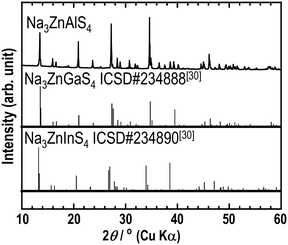
The XRPD pattern of Na3ZnAlS4, shown in Fig. 1, is significantly similar to those of Na3ZnGaS4 and Na3ZnInS4. This suggests that the three phases were isostructural. Consequently, by adjusting the cell parameters of Na3ZnGaS4, a full pattern matching was performed successfully. This yielded the refined cell parameters of a = 12.9206(1) Å, c = 18.5822(2) Å, and V = 3102.12(4) Å3 for Na3ZnAlS4. This analysis revealed the presence of impurity peaks at 18.6°, 24.7°, 26.5°, 38.7°, 38.8°, 83.2°, and 83.4°. These peaks were excluded, and Rietveld refinement was performed by using the atomic positions of Na3ZnGaS4 as the starting model. Only the Ga atom at the 32g Wyckoff position was replaced by Al. With isotropic atomic displacement parameters (ADPs), the reliability factors converged to satisfactory values. However, the Na2 atom displayed a much larger ADP than Na1 (0.087 Å2vs. 0.035 Å2). Therefore, anisotropic ADPs were applied to Na2 atoms. This resulted in the final reliability factors, refined atomic positions, and anisotropic ADPs listed in Tables 1–3, respectively. Fig. 2 shows the excellent agreement between the experimental and calculated patterns.| Crystal data | |
|---|---|
| Chemical formula | Na3ZnAlS4 |
| Mr | 289.6 |
| Crystal system space group | Tetragonal I41/acd |
| Temperature (K) | 293 |
| a (Å) | 12.9206(1) |
| c (Å) | 18.5822(2) |
| V (Å3) | 3102.12(4) |
| Z | 16 |
| Data collection | |
|---|---|
| Radiation type | Cu-Kα |
| Diffractometer | Rigaku SmartLab |
| Geometry | Bragg–Brentano |
| 2θ values (°) | 2θmin = 9.94 |
| 2θmax = 120 | |
| 2θstep = 0.02 | |
| Refinement | |
|---|---|
| R factors and goodness of fit | R p = 0.037 |
| R wp = 0.053 | |
| R exp = 0.014 | |
| R(F) = 0.057 | |
| R B = 0.097 | |
| χ 2 = 14.516 | |
| No. of parameters | 46 |
| Atom | Wyck. | Occ. | x | y | z | U iso/eq |
|---|---|---|---|---|---|---|
| Na1 | 32g | 1 | 0.1143(3) | 0.6357(3) | 0.87500 | 0.042(2) |
| Na2 | 32g | 1 | 0.1333(3) | 0.9131(3) | 0.9845(2) | 0.087(3) |
| Zn1 | 32g | 0.5 | 0.12142(13) | 0.67045(14) | 0.06233(12) | 0.0168(7) |
| Al1 | 32g | 0.5 | 0.12142(13) | 0.67045(14) | 0.06233(12) | 0.0168(7) |
| S1 | 32g | 1 | 0.25000 | 0.5819(3) | 0.00000 | 0.0240(13) |
| S2 | 32g | 1 | 0.04505(19) | 0.5403(2) | 0.12609(18) | 0.0244(11) |
| S3 | 32g | 1 | 0.00000 | 0.75000 | 0.98698(18) | 0.0139(12) |
| Atom | U 11 | U 22 | U 33 | U 12 | U 13 | U 23 |
|---|---|---|---|---|---|---|
| Na2 | 0.081(5) | 0.075(5) | 0.105(5) | −0.006(3) | −0.057(4) | 0.012(4) |
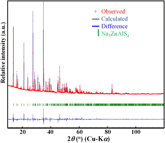 | ||
| Fig. 2 Observed (cross), calculated (solid line), and difference (bottom) XRPD patterns (Cu-Kα radiation) resulting from Rietveld refinement for Na3ZnAlS4. The impurity peaks were excluded. | ||
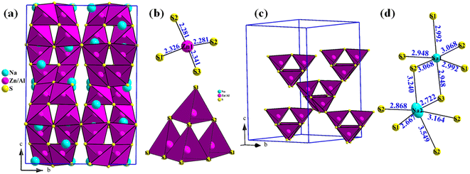
The crystal structure of Na3ZnAlS4 is shown in Fig. 3. Na3ZnAlS4 crystallizes in a β-Ca3Ga2N4-type structure.32 The structure was composed of (Zn/Al)S4 tetrahedra that shared corners and formed (Zn/Al)4S10 clusters (Fig. 3b). These clusters also shared corners and formed a 3D-(Zn/Al)4S8 framework (Fig. 3c), within which sodium atoms were located. The interatomic distances and bond valence sums (BVS)33 of Na3ZnAlS4 are listed in Table 4.
| Distance | |
|---|---|
| *Bond valence sum, B. V. = e(r0−r)/b with the following parameters: b = 0.37, r0 (NaI–S) = 2.3 Å, r0 (ZnII–S) = 2.18 Å, and r0 (AlIII–S) = 2.13 Å. The average distances are expressed as <>. | |
| Na1–S3 (×2) | 2.948(3) |
| Na1–S1 (×2) | 2.992(2) |
| Na1–S2 (×2) | 3.068(5) |
| <3.003>*0.90 | |
| Na2–S1 | 2.667(5) |
| Na2–S3 | 2.722(4) |
| Na2–S2 | 2.868(5) |
| Na2–S2 | 3.164(5) |
| Na2–S2 | 3.240(5) |
| Na2–S2 | 3.550(5) |
| <3.035>*1.11 | |
| Zn/Al1–S2 | 2.281(3) |
| Zn/Al1–S2 | 2.282(4) |
| Zn/Al1–S1 | 2.326(3) |
| Zn/Al1–S3 | 2.341(3) |
| <2.308> | |
| *2.23 for Zn | |
| *3.08 for Al | |
In the Zn/AlS4 tetrahedra, the Zn/Al–S distances varied from 2.281 Å to 2.341 Å with an average <dZn/Al–S> value of 2.308 Å. This value is lower than the average <dZn/In–S> value of 2.408 Å observed for Na3ZnInS4.30 This is in good agreement with the increase in the ionic radii of four coordinated aluminum and indium atoms from 0.39 Å to 0.62 Å.34
The Na1 and Na2 atoms occupied 32g Wyckoff positions, and both atoms were octahedrally coordinated to the sulfur atoms. Furthermore, the Na1S6 octahedra were more regular in shape than the Na2S6 octahedra, even though the average <dNa1–S> and <dNa2–S> distances of 3.003 and 3.035 Å, respectively, were similar (Table 4 and Fig. 3d). These values are similar to the average <dNa–S> of 3.029 and 3.074 Å observed in the Na3ZnInS4 compound.30 In the three Na3ZnMS4 compounds (M = Al, Ga, In), the first sodium atom exhibited larger displacement parameters than the second sodium atom (i.e., Ueq = 0.0366 Å2 and Ueq = 0.088 Å2 in Na3ZnGaS4 and Ueq = 0.0453 Å2 and Ueq = 0.1213 Å2 in Na3ZnInS4). This indicates that the first sodium atom is more mobile than the second one. This was also suggested by Hwang et al. in their study on Ca-substituted Na3ZnGaS4 compounds.28 BVS calculations yielded values of 0.90, 1.11, 2.23, and 3.03 for Na1, Na2, Zn1, and Al1, respectively. Only the Zn atom was slightly over bonded. The crystal density of Na3ZnAlS4 was calculated to be 2.49 g cm−3.
Fig. S1† shows the SEM-EDS images of Na3ZnAlS4 electrolyte. On the EDS mappings, the constituent elements Na, S, Zn and Al were almost uniformly distributed.
To increase the ionic conductivity of Na3ZnAlS4, Na vacancies were created by partially replacing Zn with Al. This led to a new composition, Na3−xZn1−xAl1+xS4 (x = 0.1, 0.15, and 0.2). The XRPD patterns of the compounds are shown in Fig. S2.† All the patterns appear similar, confirming the formation of new phases. Furthermore, when x increased, the diffraction peak 440 at 2θ = 39.5° shifted to higher angles, whereas the peak 004 at 2θ = 19.1° shifted to lower angles. This indicates that the tetragonal cell parameters a and b decrease, while c increases with x. Furthermore, full pattern-matching analyses confirmed these observations. The evolution of the cell parameters as a function of x is shown in Fig. 4 and Table S1.†
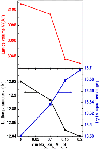 | ||
| Fig. 4 Evolution of the cell parameters as a function of x in Na3−xZn1−xAl1+xS4 (x = 0, 0.1, 0.15, and 0.2). | ||
For the Na3−xZn1−xAl1+xS4 (x = 0, 0.1, 0.15, and 0.2) compounds, the lowest and highest ionic conductivities at 25 °C were measured for the compositions x = 0 and 0.1, respectively. Therefore, for clarity, only the temperature dependences of the ionic conductivities of x = 0 and 0.1 are shown in Fig. 5. The Nyquist plot of Na2.9Zn0.9Al1.1S4 (x = 0.1) at 29.8 °C is shown in Fig. S3.† The semicircle in the high-frequency region and spike in the low-frequency region indicate that Na2.9Zn0.9Al1.1S4 is a typical ionic conducting material. Bulk and grain boundary contributions were not separated; thus, the ionic conductivities were calculated from the total resistance R, and this indicates that the Na3−xZn1−xAl1+xS4 electrolytes possess excellent formability, which enables them to exhibit high ionic conductivity even when pressed at room temperature. The temperature dependence of the ionic conductivities obeyed Arrhenius' law; therefore, the activation energies were obtained from the linear fit of log(σ) vs. 1000/T. The ionic conductivities at 25 °C and activation energies are summarized in Table 5.
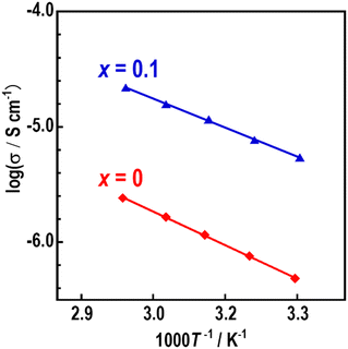 | ||
| Fig. 5 Temperature dependence of the ionic conductivities (σ) of Na3ZnAlS4 (x = 0) and Na2.9Zn0.9Al1.1S4 (x = 0.1). | ||
| x | σ 25 (S cm−1) | E a (kJ mol−1) |
|---|---|---|
| 0 | 3.8 × 10⁻⁷ | 37 |
| 0.1 | 4.5 × 10⁻⁶ | 32 |
| 0.15 | 3.5 × 10⁻⁶ | 32 |
| 0.2 | 3.8 × 10⁻⁶ | 36 |
At 25 °C, the Na3ZnAlS4 sample exhibited an ionic conductivity of 3.8 × 10⁻⁷ S cm−1 (Ea = 37 kJ mol−1), whereas Na2.9Zn0.9Al1.1S4 exhibited an ionic conductivity of 4.5 × 10⁻⁶ S cm−1 (Ea = 32 kJ mol−1), which is one order of magnitude higher than that of Na3ZnAlS4. This was due to the introduction of Na vacancies, which enhanced the ionic conductivity. A similar phenomenon was observed in Na3−xZn1−xGa1+xS4-based electrolytes. In a previous study, it was shown that vacancies were introduced at the Na2 sites, which had large ADPs, and the conductivity increased through Na2–Na2 pathways.27,28
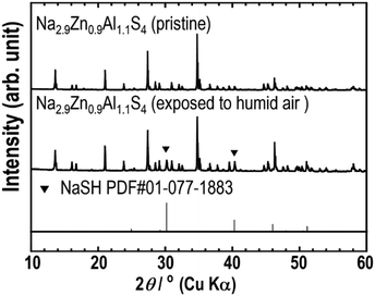
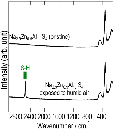
Fig. 6 and 7 show the XRPD patterns and Raman spectra of Na2.9Zn0.9Al1.1S4 before and after exposure to humid air (relative humidity: 70%) for 30 min. The XRPD pattern of Na2.9Zn0.9Al1.1S4 exposed to humid air was almost identical to that of pristine Na2.9Zn0.9Al1.1S4. However, new impurity peaks, attributable to NaSH, appeared. This was confirmed via Raman spectroscopy. On the Raman spectra, the peaks between 100 and 550 cm−1, which were attributed to pristine Na2.9Zn0.9Al1.1S4, did not change after exposure to humid air, even though the peak attributed to S–H (ref. 35) appeared at around 2550 cm−1. The previous study27,28 indicated that the Na3ZnGaS4 compound has a high humidity stability due to its open-channel structure with a network of corner-shared super-tetrahedra. Similarly, the relatively high humidity stability of Na2.9Zn0.9Al1.1S4 when exposed to humid atmosphere for a short time can be correlated with its crystal structure.
Conclusions
The new solid electrolytes (Na3−xZn1−xAl1+xS4 (x ≤ 0.2)) were prepared for the first time via a simple heat treatment using sodium polysulfides. These materials are isostructural with Na3ZnGaS4. As the aluminum content increased from 1 to 1.2, the cell volume decreased almost linearly, suggesting the formation of a solid solution. The sodium vacancies introduced by tuning the relative Zn/Al ratio in Na3−xZn1−xAl1+xS4 enhanced the ionic conductivities, and Na2.9Zn0.9Al1.1S4 exhibited the highest conductivity of 4.5 × 10⁻⁶ S cm−1 at 25 °C. Moisture stability tests showed that Na2.9Zn0.9Al1.1S4 was relatively stable when exposed to a humid atmosphere.Data availability
The data supporting this article have been included as part of the ESI.†Conflicts of interest
There are no conflicts of interest to declare.Acknowledgements
This work was supported by JSPS KAKENHI Grant Number JP23H02071 and the 2023 Osaka Metropolitan University (OMU) Strategic Research Promotion Project (Priority Research).References
- B. L. Ellis and L. F. Nazar, Curr. Opin. Solid State Mater. Sci., 2012, 16, 168–177 CrossRef CAS.
- H. Pan, Y.-S. Hu and L. Chen, Energy Environ. Sci., 2013, 6, 2338 RSC.
- N. Yabuuchi, K. Kubota, M. Dahbi and S. Komaba, Chem. Rev., 2014, 114, 11636–11682 CrossRef CAS PubMed.
- H.-L. Yang, B.-W. Zhang, K. Konstantinov, Y.-X. Wang, H.-K. Liu and S.-X. Dou, Adv. Energy Sustainability Res., 2021, 2, 2000057, DOI:10.1002/aesr.202000057.
- A. Hayashi, Electrochemistry, 2023, 91(10), 101002, DOI:10.5796/electrochemistry.23-00096.
- H. Ahmad, K. T. Kubra, A. Butt, U. Nisar, F. J. Iftikhar and G. Ali, J. Power Sources, 2023, 581, 233518 CrossRef CAS.
- A. Sakuda, A. Hayashi and M. Tatsumisago, Sci. Rep., 2013, 3, 2261 CrossRef.
- A. Hayashi, K. Noi, A. Sakuda and M. Tatsumisago, Nat. Commun., 2012, 3, 856 CrossRef PubMed.
- M. Duchardt, U. Ruschewitz, S. Adams, S. Dehnen and B. Roling, Angew. Chem., 2018, 130, 1365–1369 CrossRef.
- Z. Zhang, E. Ramos, F. Lalère, A. Assoud, K. Kaup, P. Hartman and L. F. Nazar, Energy Environ. Sci., 2018, 11, 87–93 RSC.
- F. Tsuji, K. L. Hoh, K. H. Kim, A. Sakuda, M. Tatsumisago, S. W. Martin and A. Hayashi, J. Ceram. Soc. Jpn., 2021, 129, 323–328 CrossRef CAS.
- A. Banerjee, K. H. Park, J. W. Heo, Y. J. Nam, C. K. Moon, S. M. Oh, S. T. Hong and Y. S. Jung, Angew. Chem., 2016, 128, 9786–9790 CrossRef.
- H. Wang, Y. Chen, Z. D. Hood, G. Sahu, A. S. Pandian, J. K. Keum, K. An and C. Liang, Angew. Chem., 2016, 128, 8693–8697 CrossRef.
- L. Zhang, D. Zhang, K. Yang, X. Yan, L. Wang, J. Mi, B. Xu and Y. Li, Adv. Sci., 2016, 3, 1600089, DOI:10.1002/advs.201600089.
- F. Tsuji, S. Yubuchi, A. Sakuda, M. Tatsumisago and A. Hayashi, J. Ceram. Soc. Jpn., 2020, 128, 641–647 CrossRef CAS.
- F. Tsuji, N. Masuzawa, A. Sakuda, M. Tatsumisago and A. Hayashi, ACS Appl. Energy Mater., 2020, 3, 11706–11712 CrossRef CAS.
- A. Nasu, T. Otono, T. Takayanagi, M. Deguchi, A. Sakuda, M. Tatsumisago and A. Hayashi, Energy Storage Mater., 2024, 67, 103307 CrossRef.
- T. A. Yersak, Y. Zhang, F. Hao and M. Cai, Front. Energy Res., 2022, 10, 882508, DOI:10.3389/fenrg.2022.882508.
- A. Fukushima, A. Hayashi, H. Yamamura and M. Tatsumisago, Solid State Ionics, 2017, 304, 85–89 CrossRef CAS.
- G. Sahu, Z. Lin, J. Li, Z. Liu, N. Dudney and C. Liang, Energy Environ. Sci., 2014, 7, 1053–1058 RSC.
- T. Kimura, A. Kato, C. Hotehama, A. Sakuda, A. Hayashi and M. Tatsumisago, Solid State Ionics, 2019, 333, 45–49 CrossRef CAS.
- K. Kanazawa, S. Yubuchi, C. Hotehama, M. Otoyama, S. Shimono, H. Ishibashi, Y. Kubota, A. Sakuda, A. Hayashi and M. Tatsumisago, Inorg. Chem., 2018, 57, 9925–9930 CrossRef CAS PubMed.
- H. Tang, Z. Deng, Z. Lin, Z. Wang, I.-H. Chu, C. Chen, Z. Zhu, C. Zheng and S. P. Ong, Chem. Mater., 2018, 30, 163–173 CrossRef CAS.
- T. Takayanagi, A. Nasu, F. Tsuji, K. Motohashi, A. Sakuda, M. Tatsumisago and A. Hayashi, J. Ceram. Soc. Jpn., 2022, 130, 22017 CrossRef.
- H. Gamo, N. H. H. Phuc, H. Muto and A. Matsuda, ACS Appl. Energy Mater., 2021, 4, 6125–6134 CrossRef CAS.
- S. Balijapelly, Q. Zhang, P. Sandineni, A. Adhikary, S. Mohapatra, S. Sundaramoorthy, N. Gerasimchuck, A. V. Chernatynskiy and A. Choudhury, ACS Appl. Energy Mater., 2021, 4, 7942–7951 CrossRef CAS.
- S. Han, J. Y. Seo, W. B. Park, A. B. Ikhe, S. Y. Choi, S. C. Han, K.-S. Sohn and M. Pyo, J. Mater. Chem. A, 2022, 10, 25039–25046 RSC.
- E. H. Hwang, J. Y. Seo, W. B. Park, S. Y. Kang, K.-S. Sohn and M. Pyo, J. Power Sources, 2023, 581, 233511 CrossRef CAS.
- J. Y. Seo, W.-B. Park, S. Y. Kang, Y.-K. Lee, K.-S. Sohn and M. Pyo, Energy Storage Mater., 2024, 65, 103123 CrossRef.
- R. Chen, X. Wu and Z. Su, Dalton Trans., 2018, 47, 15538–15544 RSC.
- V. Petříček, M. Dušek and L. Palatinus, Z. Kristallogr. - Cryst. Mater., 2014, 229, 345–352 CrossRef.
- S. J. Clarke and F. J. Disalvo, J. Alloys Compd., 1998, 274, 118–121 CrossRef CAS.
- I. D. Brown and D. Altermatt, Acta Crystallogr., Sect. B: Struct. Sci., 1985, 41, 244–247 CrossRef.
- R. D. Shannon, Acta Crystallogr., Sect. A: Cryst. Phys., Diffr., Theor. Gen. Crystallogr., 1976, 32, 751–767 CrossRef.
- P. Bazylewski, R. Divigalpitiya and G. Fanchini, RSC Adv., 2017, 7, 2964–2970 RSC.
Footnote |
| † Electronic supplementary information (ESI) available. See DOI: https://doi.org/10.1039/d4lf00275j |
| This journal is © The Royal Society of Chemistry 2024 |

