 Open Access Article
Creative Commons Attribution 3.0 Unported Licence
Creation of three-dimensional composite architectures via high-intensity focused ultrasound inside of foams†
Chang-Uk
Lee
 a,
Jianxun
Cui
a,
Hridyesh R.
Tewani
c,
Pavana
Prabhakar
bc and
Andrew J.
Boydston
a,
Jianxun
Cui
a,
Hridyesh R.
Tewani
c,
Pavana
Prabhakar
bc and
Andrew J.
Boydston
 *ade
*ade
aDepartment of Chemistry, University of Wisconsin, Madison, Wisconsin 53706, USA. E-mail: aboydston@wisc.edu
bDepartment of Mechanical Engineering, University of Wisconsin, Madison, Wisconsin 53706, USA
cDepartment of Civil and Environmental Engineering, University of Wisconsin, Madison, Wisconsin 53706, USA
dDepartment of Chemical and Biological Engineering, University of Wisconsin, Madison, Wisconsin 53706, USA
eDepartment of Materials Science and Engineering, University of Wisconsin, Madison, Wisconsin 53706, USA
First published on 15th April 2024
Abstract
Free-form creation of 3-dimensional (3D) structures, such as in additive manufacturing (AM) and 3D printing (3DP), typically requires a direct line-of-sight or physical contact between an energy source and a build material. By stepping away from this equipment paradigm, we discovered a method to achieve 3D composites inside of opaque, open-cell foams that enables unprecedented access to bicontinuous, interlocked composite structures. We found that high-intensity focused ultrasound (HIFU) provided efficient, localized heating at a focal point that could be spatially controlled within a foam matrix. Foam specimens were infused with thermally curable acrylate resin formulations, which enabled free-form creation of 3D structures as the HIFU focal point was moved throughout the interior of the foam. The 3D structure was created entirely based upon the toolpath, without any build plate or inherently sequenced layer-by-layer processes. Since the foam and cured resin were mechanically interlocked in the process, HIFU curing achieved bicontinuous composites seemingly independent of surface compatibilities between the foam and resin. Starting with commercially available polyurethane foams, we investigated combinations with different resin systems to achieve a range of mechanical properties from the final composite structures. For example, using poly(ethylene glycol) diacrylate (PEGDA) resulted in stiff, hard composite domains within the foam, whereas resins comprising 2-hydroxyethyl acrylate (HEA) led to soft, elastomeric composite structures. Multimaterial composites were also achieved, simply by displacing uncured resin from the foam and exchanging it with a different resin formulation. Control over the shape and orientation of internal structural features within the foam scaffolds also enabled controllable anisotropic mechanical responses from the composites.
Introduction
Complementary technologies for creating 3D structures, such as different methods of additive and hybrid manufacturing, afford vast capabilities for rapid prototyping as well as access to unique materials combinations and multi-length scale structural designs. Across most all approaches, a commonality is that the techniques require either direct physical contact or a clear line-of-sight (optical contact) between the build material and the energy or deposition source being used to set the 3D structure.1–8 We were intrigued by the possibility for free-from curing of liquid resins into solid objects within an opaque scaffold, such that resins could be cured inside of a pre-existing structure. Such a capability could enable non-invasive material synthesis inside of a living body (i.e., non-invasive implants, shunts, braces, and tissue scaffolds), unique composite structures for prostheses or orthotics, augmented mechanical properties in modified foams, and enhanced over-moulding capabilities in parts manufacturing. Unfortunately, external control over the formation of 3D parts that are internal to another object is rather limited.Notably, high-intensity focused ultrasound (HIFU) offers spatially resolved energy deposition that can be focused several inches beyond an opaque surface and can achieve mechanical as well as thermal energy transduction.9–12 HIFU techniques use a monolithic spherical or parabolic transducer to localize high power density at the focal point of the transducer. In the focal volume or area, liquid media undergo acoustic cavitation, ultimately leading to intense localized heat (up to 5000 °C), high pressure (up to 500 atmospheres), and rapid thermal cycling (heating and cooling rates greater than 109 K s−1).13 HIFU has been used as a trigger in various chemical reactions and applications. For example, HIFU can achieve thermolysis of small molecules, which can be extended to applications in the thermal ablation of tumour tissues.9,10,14,15 The mechanical-to-thermal transduction from HIFU has been used for heat-induced release of drugs or other cargo from thermally labile carriers, such as micelles or vesicles.16–20 HIFU is also used in mechanochemical transduction, in which prescribed chemical transformations are realized through induced tensile force within polymer chains. For example, Kim et al.21 reported spatiotemporal control of mechanophore activation in naphthopyran-embedded polydimethylsiloxane (PDMS) and triggering of luminescent dioxetane by HIFU. Recently, HIFU was used to pattern the thermal curing of PDMS resins. Specifically, Habibi et al.22 reported AM of a silicone resin (Sylgard 184) in focused hotspots generated by HIFU. Inspired by the achievements enabled by HIFU, we envisioned a technique that could achieve spatially resolved thermal curing within porous bodies. In this study, we report creation of unique 3D composites using two classes of resin, poly(ethylene glycol) diacrylate (PEGDA) and 2-hydroxyethyl acrylate (HEA), in commercial polyurethane foams by thermal curing mediated by HIFU.
Materials and methods
Materials, resin formulations, sample preparation
PEGDA (Mn = 700 or 575 Da), HEA (96%), potassium persulfate, ammonium persulfate, poly(ethylene glycol)-block-poly(propylene glycol)-block-poly(ethylene glycol) (PEG-PPG-PEG, Mn = 2900 Da) were each purchased from Aldrich and used as received. Hydroquinone was purchased from Acros. Commercial food dyes were purchased from Amazon.com and added to the resin solution. Deionized (DI) water was used as a coupling fluid in a water bath and was degassed using an ultrasonic degasser (Branson 2800) for at least 4 hours prior to use. Polyurethane (PU) foams with open cells were purchased from Grainger (item #5GCX4). Mylar (PET film, 0.05 mm thickness) was purchased from CS Hyde Company (item #48-2F-OC).For a PEGDA resin solution, potassium persulfate (0.7 g, 0.5 wt%, 2.6 mmol) was dissolved in DI water (20 mL), and then hydroquinone (0.18 g, 0.13 wt%, 1.6 mmol) was added to the solution. The solution was stirred for 2 minutes, and then PEGDA 700 (120 g, 6 g mL−1, 85 wt%) was added to the aqueous mixture. Three drops of a dye were then added to the mixture, and the solution was then stirred for 5 minutes. For a HEA resin solution, ammonium persulfate (0.75 g, 0.45 wt%, 3.3 mmol) was dissolved DI water (5 mL), and then hydroquinone (0.075 g, 0.045 wt%, 0.7 mmol) was added to the solution. The solution was stirred for 2 minutes, and then PEG-PPG-PEG (Mn = 2900 Da, 60 g, 36 wt%) was mixed into the aqueous solution over 2 minutes. Then, HEA (100 mL, 60.6 wt%) was added to the solution. Three drops of a dye were then added to the mixture, and the solution was then stirred for 5 minutes. After preparing the resin solutions, a cube of PU foam (50 mm × 50 mm × 50 mm) was loaded with resin solution by submerging the foam in the resin and then successively manually compressing and releasing the foam. The loaded foam sample was then placed under vacuum for 15 to 30 minutes at room temperature to degas the specimen.
HIFU system and curing conditions
The HIFU system was purchased from Sonic Concepts (Bothell, WA, USA). It is composed of a transducer (H-117) and power supply (TPO-102). There are two modes in the H-117 transducer: the central frequency of a fundamental mode is 270 kHz. That of a third harmonic mode is 916 kHz, which was used in this study. The geometric focus of the H-117 is 63.2 mm and the focal depth is 51.6 mm measured from the exit plane of the transducer housing rim to geometric focus. We operated with the estimate that the focal point is about 5 cm above the transducer. The focal size is 1.76 mm (focal width) × 12.91 mm (focal length). The transducer was placed in a bath filled with degassed DI water, which served as a coupling fluid between the transducer and the vat. The distance between the transducer and the bottom of the vat ranged from 4 to 5 cm. The duty cycle of the TPO-102 power supply was 100%, and the power used in this study ranged from 50 to 250 W. The vat was a roughly cubic shaped container (66 mm on each side) with steel plates (plate thickness = 3 mm) as walls. The open bottom of the vat was sealed by a 0.05 mm thick PET film that was glued with an epoxy adhesive to the steel walls of the vat. The top of the vat remained open. For curing experiments, a PU foam specimen that had been loaded with a resin solution was placed in the vat, which was anchored to a gantry system hanging above the transducer (Fig. 1 and video S1†). The gantry movement was dictated by G-code and had a travel speed of 500 or 550 mm min−1 for PEGDA resins and 700 mm min−1 for HEA resins. The gantry achieved movement of the vat (and therefore also of the foam specimen inside) while the HIFU transducer remained in a fixed position facing up toward the bottom of the steel vat. For curing of specific shapes, the pattern of lines, rings, or other shapes were typically retraced 5 to 7 times at the high travel speeds. After curing an object, the foam composite with resin was taken out of the vat, and any remaining resin in the foam was removed by manually squeezing it. Then, the foam composite was soaked in water, agitated by hand while submerged in water, and then air dried.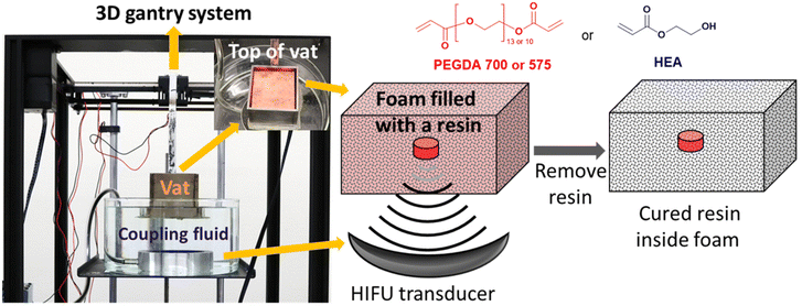 | ||
| Fig. 1 Picture of the HIFU curing setup and an idealized schematic for curing a feature inside of a foam structure. | ||
For multi-layers of PEGDA or multi-materials of PEGDA and HEA, a first structure was cured by using a resin solution with a dye. After curing a first structure from PEGDA or HEA, the resin and foam were taken out of the vat. The unreacted resin was removed, and the foam was washed with water. After drying, the foam with the first structure enclosed was loaded with another PEGDA or HEA solution (also treated with a different colour of dye from the first object) and then placed in the vat. A second structure was then cured below or next to the first one. Cylinders of PEGDA, HEA or mixtures of PEGDA and HEA were prepared by applying HIFU at one position to the foam soaked in a resin for 10 to 15 seconds without moving the gantry. To cure mixtures of PEGDA and HEA, the PEGDA resin solution was mixed with the HEA resin solution. For example, to prepare resin of PEGDA and HEA of 3![[thin space (1/6-em)]](https://www.rsc.org/images/entities/char_2009.gif) :
:![[thin space (1/6-em)]](https://www.rsc.org/images/entities/char_2009.gif) 1 by weight, 66 g of the PEGDA solution above (85 wt% of PEGDA, ca. 56 g of PEGDA) was mixed with 30.5 g of the HEA solution (60.6 wt% of HEA, ca. 18.5 g of HEA).
1 by weight, 66 g of the PEGDA solution above (85 wt% of PEGDA, ca. 56 g of PEGDA) was mixed with 30.5 g of the HEA solution (60.6 wt% of HEA, ca. 18.5 g of HEA).
Instruments
Scanning electron microscopy (SEM) was conducted using a Zeiss Gemini SEM 450 at an accelerating voltage of 2 to 7 kV. Samples for SEM were cut using a razor blade and then sputter-coated with 10 nm thick platinum. For the resin-foam composite samples under tension, the foam was torn from the composite, stretched, and then fixed on a plastic plate using an epoxy glue.
Compressive tests were done using an MTS Criterion Model 43 load frame with a 50 kN load cell at 100 mm min−1 of crosshead velocity. Compressive modulus was calculated by the slope of the stress–strain plot from strain = 0 to 0.06 mm mm−1. Average values of three experiments are reported with one standard deviation. Attenuated total reflectance infrared spectroscopy (ATR-FTIR) measurement was conducted with the Bruker Tensor 27 spectrometer. Thermogravimetric analysis (TGA) was conducted on a TA TGA Q50 under nitrogen from room temperature to 600 °C at a rate of 10 °C min−1.
Results and discussion
HIFU curing setup and thermal IR imaging
We selected acrylates as a resin class due to the broad chemical space of acrylate monomers, wide ranging materials properties of polyacrylates, and high rates of curing that can be initiated from a variety of thermal initiators (Fig. S1†). The selection of the foam for this study was largely arbitrary, although we were deliberate in choosing an open-cell foam that could be reversibly deformed by hand (a nominally soft foam). We constructed a straightforward equipment design and workflow (Fig. 1) using a modified gantry system from an extrusion 3D printer to control the movement of a steel resin vat. Efficient transduction of HIFU acoustic waves requires a coupling fluid between the HIFU transducer and the resin vat. Therefore, the vat was kept partially submerged in deionized water as a coupling fluid above the HIFU transducer. In this way, the focal point of the HIFU transducer could be moved 3-dimensionally throughout the vat. Foam specimens, which were preloaded with resin formulations, were submerged in additional resin inside the vat throughout the fabrication process.The benefits of the foam scaffolding were immediately observable when comparing the thermal profile of the HIFU irradiation into bulk resin versus a resin-loaded foam specimen (Fig. 2). Curing resin with a low viscosity (e.g., ca. 15 cP) by HIFU is challenging due to acoustic streaming and flow of the resin, causing dissipation of the heat as well as uncontrolled movement of the cured object. The long-range flow of the resin can be suppressed when the resin is soaked in an open-cell foam. The thermal images obtained during HIFU exposure in bulk resin (Fig. 2A) showed clear signs of acoustic streaming as well as heat dissipation (maximum temperature recorded = 32 °C), which precluded accurate free-form creation of solid and immobile 3D objects (video S2.1†). In contrast, the long-range flow of the resin can be suppressed when the resin is contained within an open-cell foam. Thermal imaging when HIFU was applied to resin within a foam structure (Fig. 2B) revealed more uniformly localized heating that achieved sufficient temperatures to initiate curing (>80 °C) within 5 seconds (video S2.2†). The onset temperature for curing is consistent with the temperature for the exothermic transition observed by DSC (Fig. S2 and Table S1†).
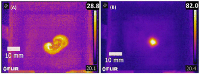 | ||
| Fig. 2 Thermal IR image of PEGDA resin solution (A) without foam and (B) soaked into foam upon HIFU exposure after 5 seconds. | ||
Presumably, curing kinetics and thermal transport each directly influence the smallest cured feature size achievable with this method. We approached this empirically by determining the diameter of cured cylinders of PEGDA-foam combinations at different exposure times of HIFU at a fixed focal volume using two variants of an open-cell foam that differed slightly in density and average pore size (Table S2 and Fig. S3†). The shortest diameter of a cured cylinder reached 6 mm at a 2-second exposure time, and the diameter increased to 19 mm at 10-second exposure. Curing resin along the surface of the denser foam that had a smaller average pore size was successful, but we found it difficult to fully saturate the foam with resin for constructing internal features. Therefore, we proceeded with the foam having larger pore size and lower density.
HIFU curing of different resin combinations in polyurethane foam
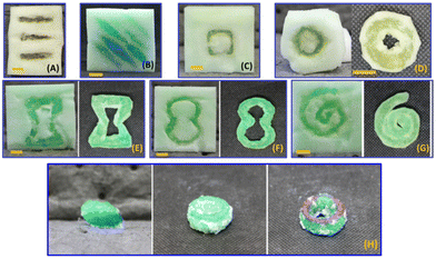
Modifications to the curing parameters based upon empirical observations enabled successful formation of 3D structures within the foam scaffolds (PEGDA in Fig. 3). The travel speed of the gantry was found to influence the resolution of the cured structures, consistent with the thermally initiated and exothermic polymerization as shown in DSC studies on PEGDA and HEA resins (Fig. S2†). At low travel speeds of 100–200 mm min−1, there was sufficient local heating and self-propagated polymerization to cure the entire volume of resin. Switching to a higher travel speed of 500–700 mm min−1 combined with multiple passes over the same path achieved controlled iterative curing with each pass. In this way, the effective duty cycle for exposure and local heating could be controlled to avoid self-propagated polymerization. Pulsed HIFU might achieve similar outcomes but was not explored in our study. Additionally, inclusion of radical inhibitors (0.1 to 0.3 wt% for PEGDA, 0.05 wt% for HEA) further improved the resolution.Next, we demonstrated a suite of geometric structures to explore the potential of HIFU curing within porous foams (Fig. 3). First, using PEGDA-based resin with a viscosity of 59.7 ± 0.2 cP, we were able to create embedded pillars (Fig. 3A and B) that indicate how isolated posts can be formed at controlled locations within the foam scaffold. Additionally, continuous pathways of cured PEGDA are demonstrated in Fig. 3C–G, which include simple geometric shapes as well as common patterns for auxetic designs (Fig. 3E and F).
We also found it to be straightforward to complete one curing session, exchange the liquid resin, and then continue fabrication of a multicomponent specimen. For example, Fig. 3H shows the results of sequential curing sessions with dyed PEGDA resins. These material combinations were achieved simply by curing first with one colour of PEGDA resin, and then exchanging the uncured resin for one of a different colour before returning to the HIFU setup.
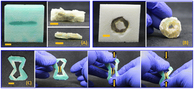
In contrast to the stiff and brittle nature of cured PEGDA, HEA-based resins give rise to soft elastomeric materials upon curing. Therefore, we explored HEA as a resin material to survey complementary mechanical properties in the final composites. Due to the viscosity of HEA being reletively low (6 cP), acoustic streaming of HEA within the foam prevented sufficient localized heating and it was difficult to achieve an onset of curing in our initial attempts. Additionally, whenever HEA polymerization was initiated, the exothermic polymerization occurred at a high enough rate to cause bulk thermal curing throughout the entire vat. As shown in Fig. S2 and Table S1,† enthalpy of fusion of HEA during the exothermic transition was ca. 2.5-fold greater than that of PEGDA 700. Attemptes to control the curing volume through HIFU exposure time was met with limited success and gave only inconsistent results. Therefore, we increased the viscosity of the formulation to 45.7 ± 0.02 cP by adding 60 wt% of PEG-PPG-PEG (Mn = 2.9 kDa, viscosity = 850 cP) to the HEA, which also increased the amount of time required to visually observe a solid, cured feature. We were then able to create lines, rings, and auxetic structures from the modified HEA resin inside the foam scaffolds (Fig. 4). Cured HEA-based composites were soft and flexible, as shown in the Fig. 4C sequence. Notably, HEA-based composites were readily deformable in contrast to PEGDA-based auxetic structures, which were too brittle to undergo reversible mechanical deformation.
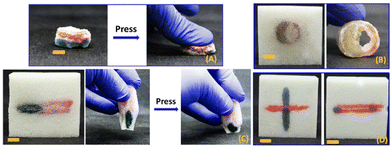
The ability to exchange the resin and continue HIFU curing enabled creation of three-component multimaterials comprising the foam, stiff PEGDA-based domains, and soft HEA-based domains (Fig. 5). Fig. 5A shows the extracted composite that resulted from sequentially curing rings of PEGDA (red) and then modified HEA resin (green). Fig. 5B–D depict additional examples of three-component composites created by sequential HIFU curing. The differences in mechanical properties of the different domains were easily discernible by qualitative manual deformation (see also video S3†).
Although the images in Fig. 3–5 are from foam specimens that had been cut to reveal the cured geometries, this is not always necessary for evaluation of the cured part. For example, the free-form creation of 3D structures inside of the foam was verified by micro-CT images, which did not require us to excavate the cured components or otherwise destroy the composite sample. Fig. 6 shows 3D reconstructions of the micro-CT scans of a stack of two PEGDA-foam composites where a post or ring of PEGDA was cured inside the foam.
Interpenetrating and interlocking networks between PEGDA or HEA with polyurethane foam
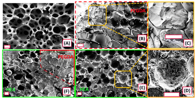
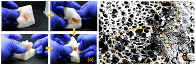
We used SEM to visualize the meso- and microscale architecture of the composites produced by HIFU curing. Fig. 7 shows SEM images of cross-sectional areas of foam (Fig. 7A), cured PEGDA in foam (Fig. 7B and C), cured HEA in foam (Fig. 7D and E), and a two-layered composite of cured PEGDA and HEA in foam (Fig. 7F). Average pore sizes of the foam (Fig. 7A) were found to be 177 ± 44 μm by analysing 30 individual pores of the SEM images using ImageJ software. Fig. 7B & C and D & E each show bicontinuous or interpenetrating networks of cured PEGDA or HEA, respectively, throughout the foam. When Fig. 7B and C are compared with Fig. 7D and E, we can see the effects of different resin compositions on the interfaces between the cured resin and the foam, which may arise from differing surface interactions or volumetric shrinkage of the cured resin. In Fig. 7B and C, there appears to be spaces or gaps between the cured PEGDA and the surface of the foam scaffold, indicating that the fidelity of the composite structure is preserved by the physical interlocking of the two materials. In contrast, cured HEA appears to more completely fill the void spaces with the foam (Fig. 7D and E) as assessed by the lack of gaps between the foam and cured HEA domains. Fig. 7E shows the interface between the cured PEGDA and HEA layers in the three-component composite. During curing, the HEA layer was created through stepwise HIFU curing, and the SEM analysis confirms that the process did not result in any separation between two resin layers. From the observation that each resin produced bicontinuous composites even though the PEDGA-based resins resulted in gaps between the cured resin and the foam, we infer that surface bonding or adhesion are not strictly required for creation of composites with this HIFU curing method.The mechanically interlocked nature of the bicontinuous composites is further demonstrated in manual tear-out experiments as depicted in Fig. 8A and video S4.† It was visually obvious that the strength of the composite was not dominated by interfacial interactions between cured resin and foam, but instead was governed by the physical architecture of the composite. We also obtained SEM images of a cured PEGDA-foam composite (Fig. 8B) that was placed under static tension during SEM. Here, there are regions of strained foam at the intersection of the cured PEGDA which simply cannot be separated until the foam reaches a breaking strain.
ATR-IR and TGA of PEGDA-PU
We conducted spectroscopic and thermogravimetric analyses on the PEGDA-foam composites prepared by HIFU. Fig. S4† shows ATR-IR spectra of the foam, PEGDA-foam composites prepared by HIFU, and thermally cured PEGDA without foam. The amide II band associated with N–H bond bending and C–N bond stretching in the urethane bond was observed from the composite at 1533 cm−1, as also observed in the PU foam at 1535 cm−1. The same signals were not found for thermally cured PEGDA without the foam. The ATR-IR spectra shows the presence of the foam in the composite. Fig. S5† shows a TGA thermogram of PEGDA-foam composite with a decomposition temperature at 5 wt% loss at 351 °C.Mechanically anisotropic properties of PEGDA-PU, and tuning modulus of the composites
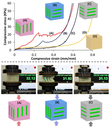
The ability to control the 3D curing of resin components inside of the foam scaffolds offered a method for creating anisotropic and generally tailorable mechanical properties in the composite specimens in which the orientations of internal posts were systematically varied (Fig. 9). Specifically, we created a series of composite cube specimens (height = 50 mm) that each contained three cylindrical posts (length = 30 mm each) formed just below the surface of each of four walls of the cube (12 posts total per cube). The cubes were subjected to uniaxial compression testing, which revealed the anisotropic mechanical behaviour of the composites. Specimen A, which had each of the 12 posts aligned with the axis of compression, showed the most significant differences in comparison with the pristine foam (Specimen D), as expected (Fig. 9 top). Specimen A displayed a comparatively high compressive modulus until ca. 20% strain, at which point the cured PEGDA posts fractured. Similar mechanical behaviour was observed from Specimen B, which had half of the posts aligned with the axis of compression and half oriented orthogonally. In comparison with Specimen A, Specimen B underwent fracture of the vertical posts at lower stress and greater strain (ca. 30%). Specimen C, which had each post oriented orthogonally to the axis of compression, showed stress–strain behaviour similar to that of the pristine foam, although the onset of compaction occurred at a lower strain for the former, as would be expected from the inclusion of the strain-limited posts inside the foam. The behaviour of Specimen C is consistent with the horizontal posts avoiding buckling and fracture, and instead simply contributing incompressible volumes within the composite. The differences in the mechanical behaviour of the composite specimens are also easily visualized in Fig. 9 bottom, in which the same compressive load was applied (ca. 31–32 N) and the compressive strain was found to be notably different across the series of cubes.Finally, we investigated the ability to tune the mechanical properties of the cured resin by systematically adjusting the feed ratios of PEGDA and HEA in the formulation. Fig. 10 shows the results of compressive tests on cylindrical composites produced with PEGDA, HEA, and PEGDA/HEA mixtures, as well as the pristine foam for comparison. The stress–strain behaviour was found to be significantly different across the series, showing characteristics that were expected based upon the dominant resin component. The modulus of the PEGDA-based composite was almost 100 times greater than that of the HEA-based system. Moving from a weight ratio for PEGDA to HEA of 100![[thin space (1/6-em)]](https://www.rsc.org/images/entities/char_2009.gif) :
:![[thin space (1/6-em)]](https://www.rsc.org/images/entities/char_2009.gif) 0 to 75
0 to 75![[thin space (1/6-em)]](https://www.rsc.org/images/entities/char_2009.gif) :
:![[thin space (1/6-em)]](https://www.rsc.org/images/entities/char_2009.gif) 25 reduced the modulus by 72% and largely flattened the low strain region of the stress–strain curve (i.e., the fracture point was less apparent for the latter composite). Shifting the ratio further in favour of HEA had progressively smaller effects on the stress–strain behaviour and modulus of each composite, indicating a handle for fine-tuning of the mechanical properties or even creating custom gradients of stiffness by repeated curing sessions with different resin formulations. Importantly, shape recovery was found to be highly dependent on the resin component of the composite. Specifically, HEA-based composites gave full shape recover even after five compressions, whereas PEGDA-based composites showed irreversible deformation after a single compression even though there were no visible signs of structural damage to the foam network (video S5†).
25 reduced the modulus by 72% and largely flattened the low strain region of the stress–strain curve (i.e., the fracture point was less apparent for the latter composite). Shifting the ratio further in favour of HEA had progressively smaller effects on the stress–strain behaviour and modulus of each composite, indicating a handle for fine-tuning of the mechanical properties or even creating custom gradients of stiffness by repeated curing sessions with different resin formulations. Importantly, shape recovery was found to be highly dependent on the resin component of the composite. Specifically, HEA-based composites gave full shape recover even after five compressions, whereas PEGDA-based composites showed irreversible deformation after a single compression even though there were no visible signs of structural damage to the foam network (video S5†).
 | ||
| Fig. 10 (A) Uniaxial compression tests on composites made from foams with PEGDA, HEA, and mixtures of PEGDA and HEA, (B) compressive modulus data of the composites at different weight fractions of PEGDA and HEA (see Table S3†), (C) pictures showing PEGDA-foam and HEA-foam composites before and after compression. | ||
Conclusions
This work demonstrates a unique method for producing 3D free-form composite structures within optically opaque porous scaffolds. The method enables thermally curable resins to be used in combination with open-cell foams to create bicontinuous, mechanically interlocked composites with different classes of materials and without any direct physical or optical contact between the energy deposition source and the cured structure. Notably, since the foam scaffold holds the entire resin, there are no build plates or inherent layers within the composite. Curing can be achieved anywhere inside of the foam and can be stopped and restarted after switching resin systems if desired, which were used to achieve mechanical heterogeneity as well as anisotropy.Author contributions
C.-U. L. and J. C. performed the HIFU experiments, resin formulations work, mechanical testing, mechanical data analysis, and initial manuscript preparation. H. R. T. performed the micro-CT scans and analysis. A. J. B. and P. P. supervised the work. All authors contributed to the revision of the manuscript.Conflicts of interest
There are no conflicts to declare.Acknowledgements
A. J. B. acknowledges partial financial support from the Yamamoto Family, the Office of the Vice Chancellor for Research and Graduate Education at the University of Wisconsin – Madison with funding from the Wisconsin Alumni Research Foundation, as well as the Army Research Office (W911NF-20-2-0182-P00005-(76555-EG-MUR)) and Office of Naval Research (N00014-23-1-2499). The authors gratefully acknowledge use of facilities and instrumentation at the UW-Madison Wisconsin Centers for Nanoscale Technology (wcnt.wisc.edu) partially supported by the National Science Foundation through the University of Wisconsin Materials Research Science and Engineering Center (DMR-1720415).References
- R. T. Shafranek, S. C. Millik, P. T. Smith, C. U. Lee, A. J. Boydston and A. Nelson, Stimuli-responsive materials in additive manufacturing, Prog. Polym. Sci., 2019, 93, 36–67 CrossRef CAS.
- G. A. Appuhamillage, N. Chartrain, V. Meenakshisundaram, K. D. Feller, C. B. Williams and T. E. Long, 110th Anniversary: Vat Photopolymerization-Based Additive Manufacturing: Current Trends and Future Directions in Materials Design, Ind. Eng. Chem. Res., 2019, 58, 15109–15118 CrossRef CAS.
- J. T. Muth, D. M. Vogt, R. L. Truby, Y. Mengüç, D. B. Kolesky, R. J. Wood and J. A. Lewis, Embedded 3D printing of strain sensors within highly stretchable elastomers, Adv. Mater., 2014, 26, 6307–6312 CrossRef CAS PubMed.
- Ľ. Hodásová, I. Isarn, F. Bravo, C. Alemán, N. Borràs, G. Fargas and E. Armelin, Synthesis of bio-sourced liquid resins and their photopolymerization with poly(ethylene glycol) diacrylate in the roadmap to more sustainable digital light processing technologies, RSC Appl. Polym., 2024, 284–295 RSC.
- Y. Lin, R. Yang and X. Wu, Recent progress in the development of conductive hydrogels and the application in 3D printed wearable sensors, RSC Appl. Polym., 2023, 1, 132–157 RSC.
- J.-R. Ai, S. Jang, W. Fink, S. H. Kim and B. D. Vogt, Role of polymer interactions in core–shell filaments in the mechanical properties of 3D printed objects, RSC Appl. Polym., 2024, 2, 105–116 RSC.
- J. Smith-Jones, N. Ballinger, N. Sadaba, X. Lopez de Pariza, Y. Yao, S. L. Craig, H. Sardon and A. Nelson, 3D printed modular piezoionic sensors using dynamic covalent bonds, RSC Appl. Polym. 10.1039/d3lp00289f.
- T. R. Klein, A. Kirillova, K. Gall and M. L. Becker, Influence of post-processing on the properties of 3D-printed poly(propylene fumarate) star polymer hydroxyapatite nanocomposites, RSC Appl. Polym., 2023, 1, 73–81 RSC.
- G. ter Haar and C. Coussios, High intensity focused ultrasound: Physical principles and devices, Int. J. Hyperthermia, 2007, 23, 89–104 CrossRef PubMed.
- S. A. Quadri, M. Waqas, I. Khan, M. A. Khan, S. S. Suriya, M. Farooqui and B. Fiani, High-intensity focused ultrasound: Past, present, and future in neurosurgery, Neurosurg. Focus, 2018, 44, 1–9 Search PubMed.
- R. J. E. van den Bijgaart, D. C. Eikelenboom, M. Hoogenboom, J. J. Fütterer, M. H. den Brok and G. J. Adema, Thermal and mechanical high-intensity focused ultrasound: perspectives on tumor ablation, immune effects and combination strategies, Cancer Immunology, Immunotherapy, 2017, 66, 247–258 Search PubMed.
- B. Liu, H. Xia, G. Fei, G. Li and W. Fan, High-intensity focused ultrasound-induced thermal effect for solid polymer materials, Macromol. Chem. Phys., 2013, 214, 2519–2527 CrossRef CAS.
- K. S. Suslick, Sonochemistry, Science, 1990, 247, 1439–1445 CrossRef CAS PubMed.
- J. E. Kennedy, High-intensity focused ultrasound in the treatment of solid tumours, Nat. Rev. Cancer, 2005, 5, 321–327 CrossRef CAS PubMed.
- Y.-F. Zhou, High intensity focused ultrasound in clinical tumor ablation, World J. Clin. Oncol., 2011, 2, 8 CrossRef PubMed.
- H. Zhang, H. Xia, J. Wang and Y. Li, High intensity focused ultrasound-responsive release behavior of PLA-b-PEG copolymer micelles, J. Controlled Release, 2009, 139, 31–39 CrossRef CAS PubMed.
- X. Liang, J. Gao, L. Jiang, J. Luo, L. Jing, X. Li, Y. Jin and Z. Dai, Nanohybrid liposomal cerasomes with good physiological stability and rapid temperature responsiveness for high intensity focused ultrasound triggered local chemotherapy of cancer, ACS Nano, 2015, 9, 1280–1293 CrossRef CAS PubMed.
- S. Dromi, V. Frenkel, A. Luk, B. Traughber, M. Angstadt, M. Bur, J. Poff, J. Xie, S. K. Libutti, K. C. P. Li and B. J. Wood, Pulsed-high intensity focused ultrasound and low temperature - Sensitive liposomes for enhanced targeted drug delivery and antitumor effect, Clin. Cancer Res., 2007, 13, 2722–2727 CrossRef CAS PubMed.
- X. Xiong, Y. Sun, A. Sattiraju, Y. Jung, A. Mintz, S. Hayasaka and K. C. P. Li, Remote spatiotemporally controlled and biologically selective permeabilization of blood-brain barrier, J. Controlled Release, 2015, 217, 113–120 CrossRef CAS PubMed.
- A. Burgess, C. A. Ayala-Grosso, M. Ganguly, J. F. Jordão, I. Aubert and K. Hynynen, Targeted delivery of neural stem cells to the brain using MRI-guided focused ultrasound to disrupt the blood-brain barrier, PLoS One, 2011, 6(11), e27877 CrossRef CAS PubMed.
- G. Kim, V. M. Lau, A. J. Halmes, M. L. Oelze, J. S. Moore and K. C. Li, High-intensity focused ultrasound-induced mechanochemical transduction in synthetic elastomers, Proc. Natl. Acad. Sci. U. S. A., 2019, 116, 10214–10222 CrossRef CAS PubMed.
- M. Habibi, S. Foroughi, V. Karamzadeh and M. Packirisamy, Direct sound printing, Nat. Commun., 2022, 13, 1800 CrossRef CAS PubMed.
- C. A. Schneider, W. S. Rasband and K. W. Eliceiri, NIH Image to ImageJ: 25 years of image analysis, Nat. Methods, 2012, 9, 671–675 CrossRef CAS PubMed.
- A. Fedorov, R. Beichel, J. Kalpathy-Cramer, J. Finet, J. C. Fillion-Robin, S. Pujol, C. Bauer, D. Jennings, F. Fennessy, M. Sonka, J. Buatti, S. Aylward, J. V. Miller, S. Pieper and R. Kikinis, 3D Slicer as an image computing platform for the Quantitative Imaging Network, Magn. Reson. Imaging, 2012, 30, 1323–1341 CrossRef PubMed.
Footnote |
| † Electronic supplementary information (ESI) available. See DOI: https://doi.org/10.1039/d4lp00002a |
| This journal is © The Royal Society of Chemistry 2024 |

