 Open Access Article
High-strength 3D printed poly(lactic acid) composites reinforced by shear-aligned polymer-grafted cellulose nanofibrils†
Peter V.
Kelly
 a,
S.
Shams Es-haghi
 bc,
Ahmad A. L.
Ahmad
 ac,
Meghan E.
Lamm
 d,
Katie
Copenhaver
d,
Elif
Alyamac-Seydibeyoglu
d,
Katie
Copenhaver
d,
Elif
Alyamac-Seydibeyoglu
 ce,
Soydan
Ozcan
 d,
Douglas J.
Gardner
cf and
William M.
Gramlich
 *ac
*ac
aDepartment of Chemistry, University of Maine, Orono, ME 04469, USA. E-mail: william.gramlich@maine.edu
bDepartment of Chemical and Biomedical Engineering, University of Maine, Orono, ME 04469, USA
cAdvanced Structures and Composites Center, University of Maine, Orono, ME 04469, USA
dManufacturing Science Division, Oak Ridge National Laboratory, Oak Ridge, TN 37748, USA
eDepartment of Chemical Engineering, Ege University, 35100 Izmir, Turkey
fSchool of Forest Resources, University of Maine, Orono, ME 04469, USA
First published on 15th November 2024
Abstract
This work demonstrates the application of pilot-scale surface functionalization of cellulose nanofibrils (CNFs) by aqueous grafting-through polymerization and subsequent spray drying in 3D printed poly(lactic acid) (PLA) composites. Grafted-CNF composites attain an ultimate tensile strength of 88 ± 3 MPa and a tensile modulus of elasticity of 7.8 ± 1.3 GPa in the printing direction at 20 wt% reinforcement loading. These increases, 42% and 139% over neat PLA, respectively, represent the strongest reported 3D printed CNF/PLA composite to date in the literature. The mechanisms behind these improvements are investigated by comparisons to neat PLA and unmodified spray-dried CNF/PLA controls using melt rheology, dynamic mechanical analysis, and assessment of the reinforcement dispersion. These experiments reveal that improved network formation and shear-induced alignment of the grafted CNFs facilitate the remarkable tensile properties of the printed composites.
Introduction
Additive manufacturing (AM) technologies are increasingly being adopted for industrial polymer processing because of their ability to produce complex architectures and rapidly implement design changes, revolutionizing research, development, and manufacturing.1 These AM processes are moving from the benchtop to the manufacturing floor via developments in tooling and printing techniques, which have enabled large-scale additive manufacturing (LSAM).2 This necessitates new printable materials for rigorous structural applications.3,4 LSAM of thermoplastic materials through melt extrusion commonly employs poly(acrylonitrile-co-butadiene-co-styrene) (ABS) or poly(ethylene terephthalate glycol) (PETg), often reinforced with carbon or glass fibre, because of their robust mechanical properties and ease of printing.5,6 Unfortunately, the increasing utilization of petroleum-derived polymers such as ABS and PETg in other applications has led to the buildup of persistent plastic waste in landfills and the environment.7 This accumulation has become an increasing concern as microplastics are found in diverse ecosystems ranging from the deep ocean floor to national parks.8,9The biodegradable polyester poly(lactic acid) (PLA) in particular has been successfully deployed as an AM feedstock because of its low processing temperature, commercial availability, and adequate strength and stiffness.10 For demanding structural applications, though, reinforced thermoplastic composites are required for the increased strength and stiffness imparted by their embedded fibre network as exemplified by carbon fibre reinforced ABS. Similarly, carbon fibre reinforcement of PLA effectively produces mechanically robust but brittle composites.11 However, a bioderived reinforcement could further mitigate the environmental impact of these materials.12 Wood flour/PLA composites, akin to commercial wood plastic composite materials, have been successfully printed with high loadings of wood filler but have diminished mechanical properties relative to neat PLA.13,14 Regenerated cellulose short fibre reinforcements can significantly improve the mechanical properties given suitable compatibilization and annealing methods.15 On the other hand, continuous natural-fibre reinforced PLA composites have shown remarkable improvements in mechanical properties when processed via AM. However, these systems require unique printing systems that coextrude the spun fibre with the PLA matrix and, so far, have not been implemented in commercial LSAM.16,17
Nanoscale bio-based reinforcements such as cellulose nanofibrils (CNFs) have the potential to surpass traditional natural fibre reinforcements because their high surface area to volume and aspect ratios allow for enhanced stress transfer from the polymer matrix and network formation at low loading levels.18 Early work with CNFs demonstrated their ability to reinforce PLA at relatively low loading levels (1–5 wt%) but relied heavily upon solvent mixing and casting to achieve good dispersion.19,20 Like other bio-based reinforcements, CNFs suffer from interfacial mismatch with polymer matrices such as PLA, an issue often addressed by chemical functionalization of the surface hydroxyls.21–24 An additional challenge to the implementation of CNFs as composite reinforcements is the need to remove the large quantities of water present in their production, which is an energy intensive process and results in the irreversible aggregation of fibrils degrading the benefits of their nanoscale properties.25
Recently, Tekinalp et al. demonstrated the potential of mechanically refined CNFs to reinforce 3D printed composites by solvent casting freeze-dried CNFs into PLA, achieving an ultimate tensile strength of around 80 MPa at 30 wt% reinforcement loading, an approximately 45% increase over neat PLA.26 This work showed that with proper dispersion CNFs could produce strong composites amenable to 3D printing; however, freeze drying and solvent casting are less commercially viable methods for composite production. Other approaches taken to facilitate 3D printing of CNFs in PLA include: the grafting-from polymerization of L-lactide followed by solvent casting (32% improvement in tensile strength),27 the solvent-based formulation of PLA Pickering emulsions stabilized by poly(L-lactide) modified CNFs followed by melt mixing (14% increase in tensile strength),28 and the addition of polyethylene glycol to freeze-dried CNFs for compatibilization and printability improvements (33% increase in filament tensile strength).29 These modification and formulation schemes represent important steps towards the incorporation of biobased CNFs into 3D printed PLA composites, but so far, the mechanical improvements imparted by traditional reinforcements have been elusive in CNF systems amenable to industrial processing technologies that typically rely on melt compounding dry reinforcements.
In this work, we aimed to overcome these previous limitations by creating a dried CNF reinforcement through a scalable process that could be melt compounded into PLA, generating composites that could be used for a pellet-fed large format 3D printer. We demonstrate how an aqueous surface modification of CNFs via grafting-through polymerization can enable 3D printed PLA composites with excellent tensile properties while employing commercially available spray drying and melt extrusion techniques.30 This grafting-through approach, previously demonstrated to preserve some of the fibrillar morphology of CNFs during spray drying,31 produced printed composite parts with x-directional tensile strengths outperforming the best CNF/PLA AM materials described in the literature. The mechanism of this remarkable improvement in strength was studied through melt rheology, fracture surface analysis, dynamic mechanical analysis (DMA), and polarized light microscopy (PLM) of composite slices to reveal the alignment of fibres in the print direction for the highest performing polymer-modified CNF composite.
Experimental methods
Materials and syntheses
Composite processing
Pilot-scale melt mixing of the composite materials for 3D printing was carried out using a 2SE 27 MAXX (Leistritz Advanced Technologies Corp, Allendale, NJ, USA) twin-screw extruder at Oak Ridge National Laboratory. PLA and reinforcements were dried overnight at 60 °C before compounding. The twelve temperature zones were set to 145 (feed zone), 150, 155, 160, 165, 170, 180, 190, 185, 185, 185, and 185 °C (die zone), respectively, down the working range of the extruder. To achieve the desired printing feedstock composition, PLA was fed gravimetrically at 8 kg h−1 and the reinforcements were added via a side feeder at 2 kg h−1. The screw speed was set at 126 rpm and a vacuum was pulled at the halfway point between CNF addition and the outlet to remove residual moisture. The extrudate was extruded as six individual strands, cooled in a water bath, and pelletized after cooling to facilitate 3D printing.
Composite characterization
The percent crystallinity (XC) of the tensile bars and extruded pellets was calculated using eqn (1) with the enthalpy of melting (ΔHm) and the enthalpy of cold crystallization (ΔHcc) obtained from the first heating cycle. The enthalpy of melting for an infinite PLA crystal (ΔH∞) was taken from literature as 93 J g−1 and the mass percent of filler (mf) was calculated based upon the melt mixing loadings.35
 | (1) |
The order parameter (S) of the composites was determined following the procedure of Chowdhury et al. although in this work the intensity of polarized light transmitted was obtained by calculating the mean pixel intensity of the unaltered images in the ImageJ software.36
Results and discussion
Modified fibril synthesis and characterization
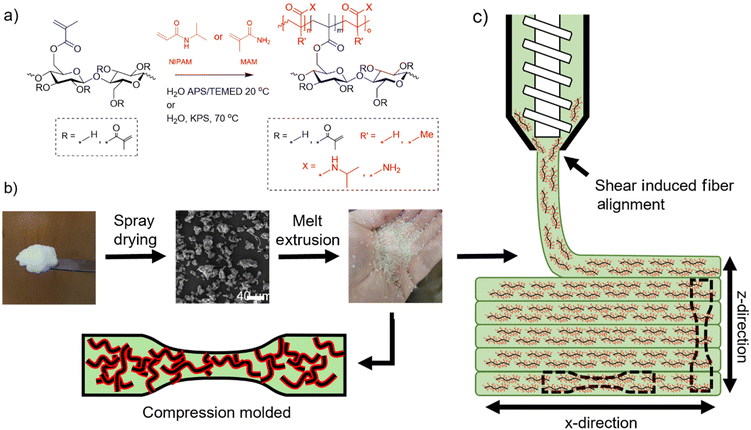
Pilot-scale production of the polymer modifications shown in Fig. 1a was conducted to yield sufficient reinforcement for pilot-scale spray drying and pellet fed extrusion-based 3D printing.The amount of polymer grafted was measured by ATR-FTIR spectroscopy (Fig. S1†) and quantified using previously published calibration curves.30 The PNIPAM-MetCNFs were calculated to be 29% ± 18% PNIPAM by mass while the PMAM-MetCNFs were calculated to be 10% ± 3% PMAM by mass. These polymer modification values are somewhat reduced compared to our previously reported smaller, bench-scale modification results,31 indicating that modifications to the reaction procedures in order to run at a larger scale can affect the total polymer modification. This behaviour indicates that future optimization at the pilot scale is needed to fully control the degree of polymer modification. The materials were purified by subsequent water washes until any unattached homopolymer or residual monomer was removed. The samples were then dried using a pilot-scale spray dryer to produce a melt-processable powder. SEM images of the spray-dried powder prior to melt compounding in Fig. 2 suggest that the polymer-modified CNF particles are larger than the spray-dried unmodified CNF (SD CNF) controls. The apparently larger particles in the SEM images are consistent with less densely packed fibril clusters for the modified materials, which may be due to reduced fibril aggregation. Powder size analysis (Table S1†) supports these observations as the polymer-modified CNFs have larger average particle sizes. We believe this is a result of the reduced density (i.e., reduced aggregation) enabling the materials to occupy more volume.
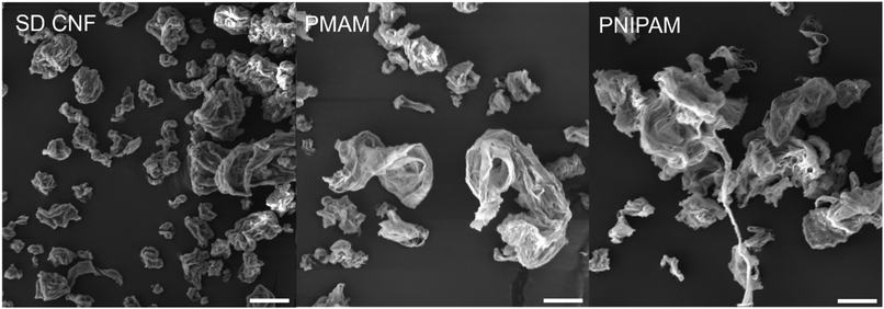 | ||
| Fig. 2 SEM images of the pilot-scale spray-dried CNF (SD CNF), PMAM-MetCNF, and PNIPAM-MetCNF samples. Scale bars represent 12 μm. | ||
Rheological characterization of composite materials
A reinforcement loading level of 20 wt% yielded the highest mechanical properties for a composition sweep using a small-scale batch melt mixer (see additional discussion in ESI Table S2 and Fig. S2 and S3†). Thus, the reinforcements were compounded into PLA at 20 wt% during pilot-scale melt mixing using a twin-screw extruder to produce pellets for 3D printing on the pellet fed printer. The rheological characterization of these composites revealed that adding the reinforcement changed the complex viscosity behaviour as a function of angular frequency (Fig. 3a). The PLA and the SD CNF/PLA composite exhibited similar plateau viscosities at lower frequencies, indicating a lack of reinforcement network formation when using SD CNFs. The polymer-modified CNF reinforced composites exhibited shear-thinning behaviour across the entire range of frequencies, deviating from this Newtonian plateau behaviour at the low frequency region.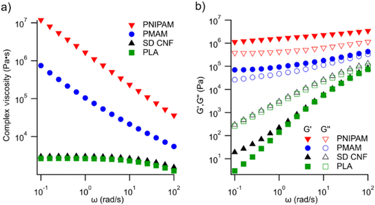 | ||
| Fig. 3 (a) The complex viscosity and (b) the storage (G′) and loss (G′′) moduli as a function of angular frequency at 200 °C of the extruded pellets at 20 wt% reinforcement loading. | ||
These changes in viscoelastic behaviour coupled with the increases in complex viscosity for the polymer-modified samples, almost three orders of magnitude higher at the lowest frequencies, indicate reinforcement network formation in the polymer-modified CNF composites.37–39 Considering the relationship between the complex viscosity and dynamic moduli, network formation is further supported by the analysis of dynamic moduli in Fig. 3b, where all the polymer-modified CNF reinforced composites showed the behaviour of a viscoelastic solid (G′ > G′′) over all frequencies. The neat PLA and the SD CNF/PLA composite both exhibited the behaviour of a viscoelastic liquid (G′′ > G′) at all frequencies, supporting the conclusion that the aggregated SD CNFs do not form an interacting network, even at 20 wt% loading. These data demonstrate that our polymer modification scheme produces a material that is better able to reinforce a PLA matrix than unmodified CNFs on a pilot scale.
3D printing and composite testing
Target extrusion temperatures for 3D printing were determined by assessing the thermal characteristics of the pellets by DSC (Table S3 and Fig. S4–S6†). A targeted melt temperature of 165 °C was chosen as all samples exhibited peak melting temperatures below this value and it represented a good balance between the printability and thermal stability of PLA. SEC analysis verified that the PLA matrix did not degrade after any of the processing steps, although a slight shift to lower molecular weights for the PNIPAM-MetCNF containing composites was observed (Fig. S7†). Printing parameters were optimized to produce a 6 mm wide bead and single walled triangular prisms were printed via a pellet-fed 3D printing process. Due to the higher viscosity of the modified CNFs, higher torques of the printer were required to yield the target bead width with these samples. Pictures of the print at different stages are shown in Fig. 4, with images of all completed prints shown in Fig. S8.† The samples were then milled to flatten the surface and cut into x-directional (parallel to the bead printing direction) and z-directional (perpendicular to the bead) samples for DMA and tensile testing as depicted in Fig. 1c. This testing scheme allowed for a simple assessment of the mechanical anisotropy in the printed samples while limiting the amount of material required to obtain sufficient replicates.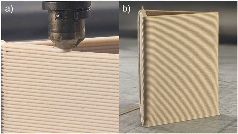 | ||
| Fig. 4 (a) Image from steady state printing showing a lack of deformation in the preceding layer under a newly extruded bead. (b) Final image of a 3D printed SD CNF control triangle prism. | ||
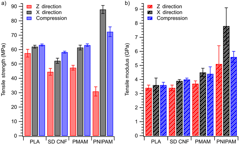
The tensile testing results in Fig. 5 and Table S4† show the pilot-scale composites of the two polymer-modified CNFs and the SD CNFs compared to a neat PLA print for the different print directions (X direction and Z direction) and the isotropic compression-moulded samples (compression) made using the extruded pellets. The compression-moulded data provide insights into the interactions of the various reinforcements and the PLA matrix without additional variables introduced by 3D printing such as void inclusion, shear induced alignment, or interlayer adhesion. The addition of SD CNFs slightly decreased the tensile strength of the isotropic compression composite, from 63.2 ± 0.7 MPa for neat PLA to 58.2 ± 0.7 MPa with 20 wt% SD CNFs, while increasing the tensile modulus of elasticity from 3.6 ± 0.2 GPa to 4.0 ± 0.1 GPa. The lack of improvement is likely the result of the aggregated SD CNF particles retaining their morphology after melt mixing. These aggregates decrease the ultimate tensile strength of the composite by acting as stress concentration points while increasing the tensile modulus by virtue of being a stiffer material, a behaviour often observed in particulate filled composite systems.40
The polymer-modified CNFs better reinforced the isotropic compression-moulded composites, exhibiting higher tensile strengths and tensile moduli at the same loading level as SD CNFs. PNIPAM-MetCNFs achieved an ultimate tensile strength of 72.4 ± 3.4 MPa and a tensile modulus of 5.6 ± 0.4 GPa while the PMAM-MetCNF composite reached 63.1 ± 0.9 MPa and 4.4 ± 0.5 GPa, respectively. These increases in strength are statistically significant at a confidence level of 95%, as discussed in the ESI (Table S5†). However, only the increase in modulus observed in the PNIPAM-MetCNF compression-moulded sample was significant compared to the SD-CNF control sample (Table S6†). This is most likely the result of improved dispersion in the matrix with qualitative evidence of this seen in the fracture surface images of the compression-moulded samples in Fig. S9.† The spray-dried CNF aggregates are left largely intact after mixing, while the polymer-modified samples, especially the PNIPAM-MetCNF composites, are more homogeneous. The viscoelastic characterization of the composites in Fig. 3 further corroborates this analysis of the underlying particle dispersion and helps explain the tensile behavior shown in Fig. 5 and Fig. S10.† The PNIPAM-MetCNFs and, to a lesser extent, the PMAM-MetCNFs exist as dispersed networks of fibrils and fibers that more effectively reinforce the composites than the SD CNFs, which act as isolated aggregates inside the PLA matrix. This improved dispersion and tensile properties can be attributed to the previously observed lower dispersive component of surface energy of the PNIPAM-MetCNFs (17.6 mJ m−2) as compared to the SD CNFs (49.0 mJ m−2) and PMAM-MetCNFs (34.8 mJ m−2).31 Increased crystallinity nucleated by the reinforcements was considered as a potential factor in the tensile results, but DSC analysis showed that the degree of crystallinity in each material was very low regardless of processing conditions (Table S3 and Fig. S4–S6†). These tensile results match well with the trends of the small-scale batch melt mixing data seen in Fig. S2,† confirming that the small scale screening can be used to direct reinforcement loading levels.
The most striking result of the 3D printing tests were the dramatic changes in the mechanical properties of the materials compared to the isotropic compression-moulded samples. The PNIPAM-MetCNF composite exhibited a remarkable increase in tensile strength and tensile stiffness in the x direction of the print, achieving an ultimate tensile strength of 87.9 ± 2.8 MPa and a tensile stiffness of 7.8 ± 1.3 GPa, a 42% and 129% increase, respectively, compared to neat PLA. In comparison, the PMAM-MetCNF sample remained unchanged while the SD CNF/PLA decreased in strength to 52.2 ± 1.8 MPa with no significant change in tensile stiffness. This PNIPAM-MetCNF composite exhibits the highest x-directional tensile strength observed to date in the literature for CNF reinforced PLA produced by 3D printing. The work also benefits from not requiring the use of solvent casting to preserve the reinforcement architecture and employing industrially scalable drying and compounding technologies. The hypothesized mechanism of this increase in tensile strength was the alignment of these modified fibrils during extrusion, which is attributable to the shear imparted by the walls of the print nozzle, a phenomenon known to improve mechanical properties dramatically in PLA composites.41,42 With this increase in tensile strength, the PNIPAM-MetCNF/PLA composite could potentially replace previously demonstrated wood flour/PLA composites used for LSAM to create durable goods such as concrete formwork,43 culvert diffusers,44 and houses,45 while either using less composite material or yielding stronger final products.
As seen in Fig. 5, the z-directional strength of all reinforced composites was lower than that of the PLA control, which had relatively isotropic mechanical properties. The PNIPAM-MetCNF sample exhibited the lowest z-directional strength with an ultimate tensile strength of 30.9 ± 2.7 MPa in comparison with the 47.4 ± 2.1 MPa and 44.5 ± 2.5 MPa measured for the PMAM-MetCNF and SD CNF composites, respectively. The mechanical properties of extrusion-based 3D printed parts are well known to be anisotropic, with different print geometries and processing conditions resulting in a range of values at different orientations.46–49 This behaviour is multifaceted, but one cause is poor adhesion between printed layers. The poor adhesion can be caused by a combination of poor physical contact and reduced polymer entanglement between beads. This latter phenomenon results from slower chain diffusion across the interface of the hot extruded layer and the cooler preceding layer and is well studied in the field of thermoplastic adhesion.50,51 Bhandari et al. found that in carbon fibre reinforced PLA, the higher viscosity of the composite led to lower interlayer adhesion than in the neat, printed PLA. This could be alleviated by annealing the parts above the Tg, and it was concluded that a higher melt viscosity during printing led to poor interlayer diffusion.52 This conclusion supports our results where the lowest interfacial adhesion was observed for the highest viscosity composite (PNIPAM-MetCNF). Those previous reports also suggest that in future studies annealing of the PNIPAM-MetCNF composite could possibly improve this interlayer adhesion, leading to improved z-directional strength and elongation at break.
Analysis of printed composite morphology
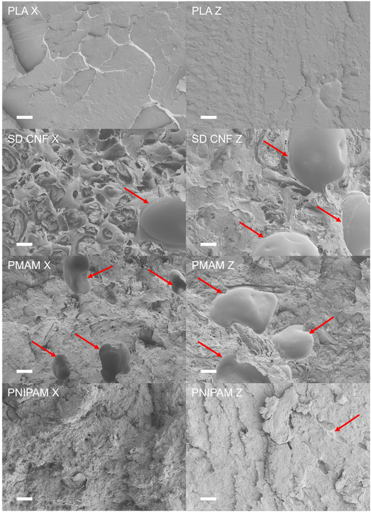
The 3D printing of thermoplastic composites can produce unique morphological features including different types of voids and filler alignment that can dramatically impact measured mechanical properties relative to traditional manufacturing methods.53–55 The composite morphologies were characterized by SEM and optical microscopy to further explain the differences observed among the samples. Significant void formation was observed in both the PMAM-MetCNF and SD CNF composites in both the x- and z-direction fracture surfaces (Fig. 6 and Fig. S11 and S12†). The inter-bead voids observed in the z-direction fracture surfaces of the PMAM-MetCNF and SD CNF samples would decrease the interlayer strength and explains why the SD CNF composite had a lower interlayer strength than the neat PLA despite having similar melt viscosity. The intra-bead voids seen in the x-direction fracture surfaces would similarly decrease strength in the print direction by decreasing the effective cross-sectional area and acting as stress concentration sites during deformation. Inter-bead voids are thought to form during 3D printing of filled composites attributable to reduced diffusion of polymer chains across the interface56 while intra-bead voids are thought to form because of the die swell of the bead as it exits the nozzle and the differential cooling of the surface relative to the bulk.55 Different coefficients of thermal expansion between the components and poor interfacial interactions can cause the filler and the matrix to separate.57Interestingly, the PNIPAM-MetCNF printed samples had few voids in comparison, which is likely attributable to the lower dispersive component of the surface energy (17.6 mJ m−2 for PNIPAM-MetCNFs versus 49.0 mJ m−2 for SD CNFs) leading to better interfacial interactions with the matrix and improved fibril dispersion.31 The spherical SD CNF particles, in contrast, debonded from the PLA matrix (Fig. 6), which is likely attributable to the poor interfacial adhesion between the reinforcement and matrix as noted in our previous study.31 The magnitude of these morphological effects will be dependent upon a combination of the composite viscoelastic properties and the specific print conditions chosen, posing the opportunity for future studies to optimize print parameters. The lack of voids in the printed sample and improvements in dispersion help explain the increased tensile strength seen in the x-directional PNIPAM-MetCNF composite but do not fully account for the increase over the compression-moulded control, which also contained limited voids and good fibril dispersion (Fig. S9†). The orientation and dispersion of reinforcement fibrils were explored by imaging microtomed sections of the composites with traditional and polarized light microscopy. The images in Fig. 7a and Fig. S13 and S14† reveal how the population of fibrils and particles, those visible by optical microscopy, are dispersed inside both the printed composites and the compression-moulded controls. First, the PNIPAM-MetCNFs are more dispersed than either the PMAM-MetCNFs or the SD CNFs. Both the printed (Fig. S13 and S14 left†) and the compression-moulded samples (Fig. S13 and S14 right†) have elements that appear more individualized and fibrillated. The PMAM-MetCNFs appear more dispersed than the SD CNF samples as evidenced by more diffuse appearances and a less clear contrast between the matrix and reinforcement. This qualitative evaluation is supported by the higher complex viscosities in the rheological characterization (Fig. 3b) and may account for their higher tensile strength and tensile stiffness.
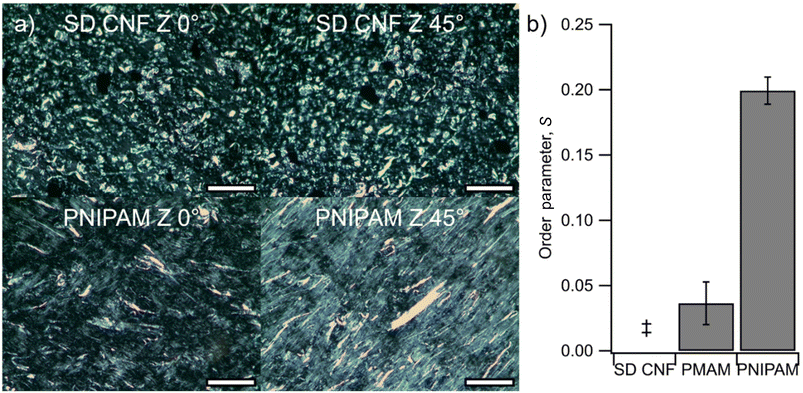
Polarized light microscopy (PLM) images taken of microtomed composites were used to quantify the alignment of CNFs in the samples following the work of Chowdhury et al. on oriented CNC films.36 The birefringence of crystalline cellulose domains and their alignment in cellulose fibrils allows for CNF orientation to be quantified in a similar way to that of CNCs.58Fig. 7a shows representative images of the 3D printed SD CNF and PNIPAM-MetCNF composites, with large aggregates in the SD CNF sample visible, which is attributable to the crystalline domains of cellulose in the fibers being randomly distributed in the particles.
No intensity change is seen in the SD CNF sample when rotated relative to the polarizers, indicating no long-range order. In contrast, the PNIPAM-MetCNF composite images show a clear increase in intensity when oriented at 45°, indicating that a population of fibrils in the sample are oriented. The changes in intensity of the transmitted light between 0° and 45° film orientations were used to calculate an order parameter (S) between 0 and 1, with 0 representing an isotropic orientation of the cellulose crystalline domains and 1 representing a fully ordered orientation.
Fig. 7b compares the 3D printed composite materials and shows essentially no ordering in the SD CNF composite or the PMAM-MetCNF composite but a modest amount of ordering in the PNIPAM-MetCNF composite with an order parameter of 0.2. The compression-moulded control samples of all composites showed essentially no ordering (Table S7†), demonstrating that the better dispersion of the PNIPAM-MetCNFs in the PLA matrix was unique in allowing orientation of the fibrils with the shear induced by the 3D printing process. This analysis looked at the alignment of fibrils in only a small cross section of the printed bead, but the results support the conclusion that the improvements in mechanical properties for the printed PNIPAM-MetCNF composite are likely because of this alignment.
Dynamic mechanical analysis of composite anisotropy
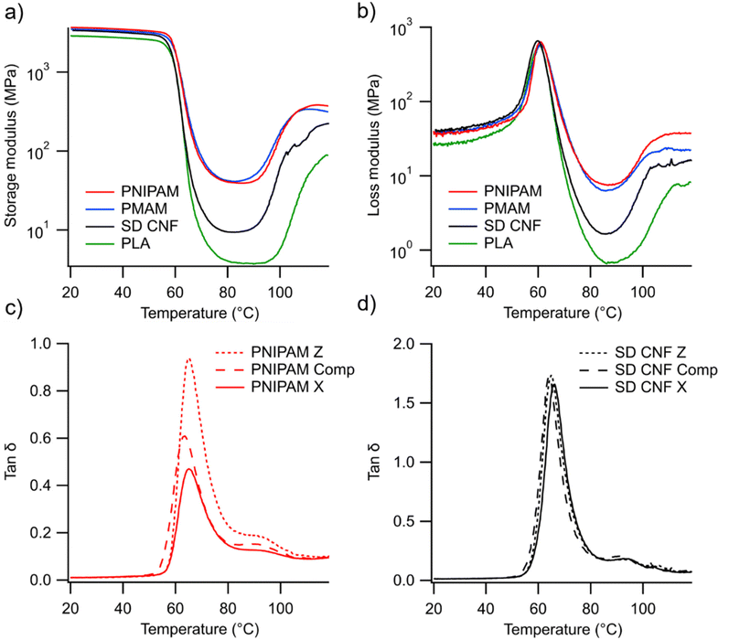
A DMA study was conducted to explore the effects of the reinforcements on the viscoelastic properties of the composites and understand how the directionality affects their behaviour after printing. Samples were milled from the 3D printed parts in both the x- and z-directions and pellets were compression-moulded to create isotropic controls. The data in Fig. 8a and b compare the viscoelastic response of the four printed samples in the x-direction with noticeable changes in both the glassy region and the rubbery regions of the curves. The increases in dynamic moduli starting at around 90 °C in these data are attributed to cold crystallization of the PLA matrix as seen in the DSC traces (Fig. S6†). The PNIPAM-MetCNF sample shows the largest deviation from the PLA with a 67% increase in the glassy storage moduli (G′) and an almost three-orders of magnitude increase in the rubbery storage moduli. Similarly, the rubbery plateau loss moduli (G′′) values were almost two orders of magnitude higher for the PNIPAM-MetCNF samples than for the PLA. The dynamic moduli values for the other composites increased as well, with the PMAM-MetCNF sample falling between the PNIPAM-MetCNF and SD CNF composites. These results follow the trend observed in the tensile moduli (Fig. 5b) and can be understood as resulting from improved reinforcement of the composites by the fibrils, brought about by their superior dispersion as seen in Fig. 7. The increase in both storage and loss moduli, representing energy stored elastically and dissipated viscously, respectively, may seem counter-intuitive for a stiffer reinforced composite but results from more total energy being required to deform the stiffer system to a set strain value. This is a phenomenon observed widely in the reinforced thermoplastic composite literature.24,59,60These trends in relative dynamic moduli (Fig. S14, S15, and Table S8†) remain consistent within each testing direction, showing that the PNIPAM-MetCNFs reinforce the composite more effectively than the PMAM-MetCNFs, which similarly are more effective than the SD CNFs. Similarly, the tan![[thin space (1/6-em)]](https://www.rsc.org/images/entities/char_2009.gif) δ curves in Fig. 8 and Fig. S16† reveal that the PNIPAM-MetCNF composite stores a higher ratio of energy elastically than the SD CNF composites regardless of orientation. The PNIPAM-MetCNF composite is the only sample to exhibit significant anisotropy in the DMA analyses, with the x-directional rubbery plateau storage moduli (245 ± 23 MPa) being about double that of the isotropic sample (121 ± 6 MPa), which is about triple that of the z-directional samples (40 ± 2 MPa). This anisotropy is consistent across both the loss moduli and tan
δ curves in Fig. 8 and Fig. S16† reveal that the PNIPAM-MetCNF composite stores a higher ratio of energy elastically than the SD CNF composites regardless of orientation. The PNIPAM-MetCNF composite is the only sample to exhibit significant anisotropy in the DMA analyses, with the x-directional rubbery plateau storage moduli (245 ± 23 MPa) being about double that of the isotropic sample (121 ± 6 MPa), which is about triple that of the z-directional samples (40 ± 2 MPa). This anisotropy is consistent across both the loss moduli and tan![[thin space (1/6-em)]](https://www.rsc.org/images/entities/char_2009.gif) δ and is unique to this material. Dynamic mechanical anisotropy has been seen in the literature for 3D printed samples and been attributed to a variety of causes: polymer chain alignment, void orientation, and fibre alignment, in the case of fibre reinforced composites.61–63 While all of these factors could play a role in the observed anisotropy of the PNIPAM-MetCNF composite, the alignment observed in the PLM data most likely contributes heavily to the directionality in the viscoelastic properties measured.
δ and is unique to this material. Dynamic mechanical anisotropy has been seen in the literature for 3D printed samples and been attributed to a variety of causes: polymer chain alignment, void orientation, and fibre alignment, in the case of fibre reinforced composites.61–63 While all of these factors could play a role in the observed anisotropy of the PNIPAM-MetCNF composite, the alignment observed in the PLM data most likely contributes heavily to the directionality in the viscoelastic properties measured.
The appearance of fibril alignment in this printed sample is consistent with work exploring the alignment of cellulose nanocrystal (CNC) composites during printing. Calabrese et al. demonstrated that extensional and shear flows affected the alignment of CNCs in printing inks and found that a high Péclet number, a ratio of deformation rate to the particle diffusion coefficient, predisposed the system to alignment.64 The diffusion coefficient of CNFs is known to be orders of magnitude lower than that of CNCs due to their higher aspect ratios and size, which yields a relatively higher Péclet number that should increase their susceptibility to fibril alignment during shear.65 While fibril alignment was demonstrated experimentally in our work, the degree of alignment throughout the bead was not modelled as multiple parameters such as residence time under shear, matrix viscosity, nozzle geometry, and CNF aspect ratio all cooperatively dictate the degree of alignment.66 Aspect ratio is challenging to define for a hierarchical material such as the mechanically refined CNFs used here. Also, these data demonstrate alignment of a portion of the CNF population but whether the fibrils not visible by optical microscopy are also aligned with the print direction is unknown. For these reasons, possible additional processing optimization could increase the levels of alignment in similar systems and further improve mechanical properties.
Conclusions
In this work we have demonstrated the pilot-scale production, compounding, and 3D printing of PLA reinforced with polymer-modified CNFs. Our PNIPAM-modified CNF reinforced composite achieved the highest reported tensile strength to date for 3D printed CNF reinforced PLA. The utilization of industrially scalable grafting-through polymerization and spray-drying, twin-screw extrusion, and extrusion-based 3D printing lowers the barriers of entry into industrial adoption. The results of this work highlight the importance of preserving the fibrillar architecture during each processing step to ensure adequate fibrillation of the reinforcements in the composite matrix. Alignment of the fibrils, demonstrated here to dramatically improve tensile properties, is reliant upon adequate dispersion and was not observed in the more aggregated reinforcements. Future work in this area could seek to achieve comparable mechanical properties with a lower loading level of modified fibrils by optimizing interfacial interactions between the polymer-grafted CNFs and the PLA, modifying drying conditions to produce more fibrillated reinforcements, and optimizing printing conditions to promote alignment and interlayer adhesion. The results presented here further highlight how the codependent properties of CNF dispersion, interfacial compatibility, and composite processing can facilitate high-strength 3D printed composites.Author contributions
P. K. contributed to formal analysis, investigation, methodology, visualization, writing – original draft, and writing – review & editing. S. S. contributed to formal analysis, investigation, methodology, and writing – review & editing. A. A. contributed to formal analysis, investigation, and methodology. M. L. contributed to formal analysis, investigation, and methodology. K. C. contributed to formal analysis, investigation, and methodology. E. A.-S. contributed to conceptualization, formal analysis, investigation, and writing – review & editing. S. O. contributed to funding acquisition, project administration, and resources. D. G. contributed to conceptualization, funding acquisition, methodology, project administration, supervision, and writing – review & editing. W. G. contributed to conceptualization, funding acquisition, methodology, project administration, and writing – review & editing.Data availability
The data supporting this article have been included as part of the ESI.†Conflicts of interest
There are no conflicts to declare.Acknowledgements
This material is based upon work supported by the US Department of Energy (DOE), Office of Energy Efficiency and Renewable Energy, Advanced Materials and Manufacturing Office under CPS Agreement 35863, and Oak Ridge National Laboratory/University of Maine SM2ART program with research and resources used at the Manufacturing Demonstration Facility (MDF), a DOE AMMTO User Facility; the Advanced Structures and Composites Center (ASCC), a University of Maine research center; and the University of Maine. The authors thank Dr Emma Perry of the University of Maine electron microscope laboratory for her support and assistance in this work. They would also like to thank Wesley Bisson and Spencer Sansouci of the University of Maine Advanced Structures and Composite Center for their assistance with the composite 3D printing.References
- Krishnanand and M. Taufik, in Advanced Manufacturing Systems and Innovative Product Design, ed. B. B. V. L. Deepak, D. R. K. Parhi and B. B. Biswal, Springer, Singapore, 2021, pp. 497–505 Search PubMed.
- C. E. Duty, V. Kunc, B. Compton, B. Post, D. Erdman, R. Smith, R. Lind, P. Lloyd and L. Love, Rapid Prototyp. J., 2017, 23, 181–189 CrossRef.
- D. M. Bigg, D. F. Hiscock, J. R. Preston and E. J. Bradbury, J. Thermoplast. Compos. Mater., 1988, 1, 146–160 CrossRef.
- A. Sola, Macromol. Mater. Eng., 2022, 307, 2200197 CrossRef CAS.
- B. G. Compton, B. K. Post, C. E. Duty, L. Love and V. Kunc, Addit. Manuf., 2017, 17, 77–86 CAS.
- D. Yavas, Z. Zhang, Q. Liu and D. Wu, Compos. Sci. Technol., 2021, 208, 108741 CrossRef CAS.
- R. Geyer, J. R. Jambeck and K. L. Law, Sci. Adv., 2017, 3, e1700782 CrossRef.
- M. B. Tekman, T. Krumpen and M. Bergmann, Deep Sea Res., Part I, 2017, 120, 88–99 CrossRef.
- J. Brahney, M. Hallerud, E. Heim, M. Hahnenberger and S. Sukumaran, Science, 2020, 368, 1257–1260 CrossRef CAS.
- M. Lay, N. L. N. Thajudin, Z. A. A. Hamid, A. Rusli, M. K. Abdullah and R. K. Shuib, Composites, Part B, 2019, 176, 107341 CrossRef CAS.
- X. Tian, T. Liu, Q. Wang, A. Dilmurat, D. Li and G. Ziegmann, J. Cleaner Prod., 2017, 142, 1609–1618 CrossRef CAS.
- S. Bhagia, K. Bornani, R. Agrawal, A. Satlewal, J. Ďurkovič, R. Lagaňa, M. Bhagia, C. G. Yoo, X. Zhao, V. Kunc, Y. Pu, S. Ozcan and A. J. Ragauskas, Appl. Mater. Today, 2021, 24, 101078 CrossRef.
- J. V. Ecker, A. Haider, I. Burzic, A. Huber, G. Eder and S. Hild, Rapid Prototyp. J., 2019, 25, 672–678 CrossRef.
- S. Kain, J. V. Ecker, A. Haider, M. Musso and A. Petutschnigg, Eur. J. Wood Prod., 2020, 78, 65–74 CrossRef CAS.
- C. Gauss, K. L. Pickering, N. Graupner and J. Müssig, Addit. Manuf., 2023, 77, 103806 CAS.
- A. Le Duigou, A. Barbé, E. Guillou and M. Castro, Mater. Des., 2019, 180, 107884 CAS.
- A. Le Duigou, G. Chabaud, R. Matsuzaki and M. Castro, Composites, Part B, 2020, 203, 108474 CAS.
- X. Xu, F. Liu, L. Jiang, J. Y. Zhu, D. Haagenson and D. P. Wiesenborn, ACS Appl. Mater. Interfaces, 2013, 5, 2999–3009 CrossRef CAS.
- M. Jonoobi, J. Harun, A. P. Mathew and K. Oksman, Compos. Sci. Technol., 2010, 70, 1742–1747 CrossRef CAS.
- A. Iwatake, M. Nogi and H. Yano, Compos. Sci. Technol., 2008, 68, 2103–2106 CrossRef CAS.
- V. Žepič, I. Poljanšek, P. Oven and M. Čop, Holzforschung, 2016, 70, 1125–1134 CrossRef.
- N. Jamaluddin, T. Kanno, T.-A. Asoh and H. Uyama, Mater. Today Commun., 2019, 21, 100587 CrossRef CAS.
- M. E. Driscoll, P. V. Kelly and W. M. Gramlich, Langmuir, 2023, 39, 7079–7090 CrossRef CAS PubMed.
- M. E. Lamm, K. Li, K. Copenhaver, P. V. Kelly, H. Senkum, H. Tekinalp, W. M. Gramlich and S. Ozcan, ACS Appl. Polym. Mater., 2022, 4, 7674–7684 CrossRef CAS.
- Y. Peng, D. J. Gardner and Y. Han, Cellulose, 2012, 19, 91–102 CrossRef CAS.
- H. L. Tekinalp, X. Meng, Y. Lu, V. Kunc, L. J. Love, W. H. Peter and S. Ozcan, Composites, Part B, 2019, 173, 106817 CrossRef.
- J. Dong, M. Li, L. Zhou, S. Lee, C. Mei, X. Xu and Q. Wu, J. Polym. Sci., Part B: Polym. Phys., 2017, 55, 847–855 CrossRef CAS.
- C. Gauss and K. L. Pickering, Addit. Manuf., 2023, 61, 103346 CAS.
- Q. Wang, C. Ji, L. Sun, J. Sun and J. Liu, Molecules, 2020, 25, 2319 CrossRef CAS PubMed.
- P. V. Kelly, P. Cheng, D. J. Gardner and W. M. Gramlich, Macromol. Rapid Commun., 2021, 42, 2000531 CrossRef CAS.
- P. V. Kelly, S. Shams Es-haghi, M. E. Lamm, K. Copenhaver, S. Ozcan, D. J. Gardner and W. M. Gramlich, ACS Appl. Polym. Mater., 2023, 5, 3661–3676 CrossRef CAS.
- M. A. Bilodeau and M. A. Paradis, United States, 9988762, 2018 Search PubMed.
- P. V. Kelly, D. J. Gardner and W. M. Gramlich, Carbohydr. Polym., 2021, 273, 118566 CrossRef CAS PubMed.
- S. Christau, E. Alyamac-Seydibeyoglu, K. Thayer and W. M. Gramlich, Cellulose, 2023, 30, 901–914 CrossRef CAS.
- S. Farah, D. G. Anderson and R. Langer, Adv. Drug Delivery Rev., 2016, 107, 367–392 CrossRef CAS PubMed.
- R. A. Chowdhury, S. X. Peng and J. Youngblood, Cellulose, 2017, 24, 1957–1970 CrossRef CAS.
- L. Cui, L. Yi, Y. Wang, Y. Zhang, P. Polyák, X. Sui and B. Pukánszky, Mater. Des., 2021, 206, 109774 CrossRef CAS.
- M. R. Kamal and V. Khoshkava, Carbohydr. Polym., 2015, 123, 105–114 CrossRef CAS.
- D. S. Bangarusampath, H. Ruckdäschel, V. Altstädt, J. K. W. Sandler, D. Garray and M. S. P. Shaffer, Polymer, 2009, 50, 5803–5811 CrossRef CAS.
- L. Aliotta, P. Cinelli, M. B. Coltelli and A. Lazzeri, Eur. Polym. J., 2019, 113, 78–88 CrossRef CAS.
- S. Geng, K. Yao, Q. Zhou and K. Oksman, Biomacromolecules, 2018, 19, 4075–4083 CrossRef CAS.
- A. A. Singh, S. Geng, N. Herrera and K. Oksman, Composites, Part A, 2018, 104, 101–107 CrossRef CAS.
- S. Bhandari, R. Lopez-Anido and J. Anderson, in Proceedings of the Conference & Exhibition on Thermoplastic Composites, Bremen, Germany, 2020, pp. 13–14.
- S. Bhandari, R. A. Lopez-Anido, J. Anderson and A. Mann, in SPE ANTEC, Online, 2021 Search PubMed.
- J. Ferrini-Mundy and K. Varahramyan, 2022 Research Report: R1 Global Impact-Local Relevance, University of Maine, Orono, ME, USA, 2023 Search PubMed.
- R. J. Zaldivar, D. B. Witkin, T. McLouth, D. N. Patel, K. Schmitt and J. P. Nokes, Addit. Manuf., 2017, 13, 71–80 CAS.
- A. R. Torrado and D. A. Roberson, J. Fail. Anal. Prev., 2016, 16, 154–164 CrossRef.
- M. Domingo-Espin, J. M. Puigoriol-Forcada, A.-A. Garcia-Granada, J. Llumà, S. Borros and G. Reyes, Mater. Des., 2015, 83, 670–677 CrossRef CAS.
- A. C. Abbott, G. P. Tandon, R. L. Bradford, H. Koerner and J. W. Baur, Addit. Manuf., 2018, 19, 29–38 CAS.
- R. Gurney, A. Henry, R. Schach, A. Lindner and C. Creton, Langmuir, 2017, 33, 1670–1678 CrossRef CAS PubMed.
- F. Awaja, Polymer, 2016, 97, 387–407 CrossRef CAS.
- S. Bhandari, R. A. Lopez-Anido and D. J. Gardner, Addit. Manuf., 2019, 30, 100922 CAS.
- Y. Tao, F. Kong, Z. Li, J. Zhang, X. Zhao, Q. Yin, D. Xing and P. Li, J. Mater. Res. Technol., 2021, 15, 4860–4879 CrossRef CAS.
- S. Yu, H. Bale, S. Park, J. Y. Hwang and S. H. Hong, Composites, Part B, 2021, 224, 109184 CrossRef CAS.
- D. Yang, H. Zhang, J. Wu and E. D. McCarthy, Addit. Manuf., 2021, 37, 101686 CAS.
- Y. Satapathy, V. Nikitin, J. Hana, K. R. Venkatesan, F. Tran, S. Chen, P. Shevchenko, F. De Carlo, R. Kettimuthu, S. Zekriardehani, J. Mapkar, A. Krishnamurthy and A. Tekawade, Addit. Manuf., 2024, 86, 104199 CAS.
- H. L. Tekinalp, V. Kunc, G. M. Velez-Garcia, C. E. Duty, L. J. Love, A. K. Naskar, C. A. Blue and S. Ozcan, Compos. Sci. Technol., 2014, 105, 144–150 CrossRef CAS.
- S. Ghasemi, P. Rahimzadeh-Bajgiran, M. Tajvidi and S. M. Shaler, Cellulose, 2020, 27, 677–692 CrossRef CAS.
- L. A. Pothan, Z. Oommen and S. Thomas, Compos. Sci. Technol., 2003, 63, 283–293 CrossRef CAS.
- N. G. Karsli and A. Aytac, Composites, Part B, 2013, 51, 270–275 CrossRef CAS.
- S. Dul, L. Fambri and A. Pegoretti, Composites, Part A, 2016, 85, 181–191 CrossRef CAS.
- I. M. Alarifi, Polym. Compos., 2022, 43, 5353–5363 CrossRef CAS.
- M. S. Anoop, P. Senthil and V. S. Sooraj, J. Braz. Soc. Mech. Sci. Eng., 2021, 43, 38 CrossRef.
- V. Calabrese, S. J. Haward and A. Q. Shen, Macromolecules, 2021, 54, 4176–4185 CrossRef CAS.
- K. Fein, D. W. Bousfield and W. M. Gramlich, ACS Appl. Polym. Mater., 2021, 3, 3666–3678 CrossRef CAS.
- M. K. Hausmann, P. A. Rühs, G. Siqueira, J. Läuger, R. Libanori, T. Zimmermann and A. R. Studart, ACS Nano, 2018, 12, 6926–6937 CrossRef CAS PubMed.
Footnote |
| † Electronic supplementary information (ESI) available: Experimental methods, FT-IR analysis of materials, tabulated tensile testing data, DSC curves and thermal properties of composites, SEC elution curves, fracture surface SEM images, optical microscopy images of composites, and DMA curves of composites. See DOI: https://doi.org/10.1039/d4lp00283k |
| This journal is © The Royal Society of Chemistry 2025 |

