 Open Access Article
A high heat dissipation strategy based on a multi-scale porous hydrogel and heat sink exhibiting cooling capacity comparable to that of forced air convection but with zero energy consumption†
Kaifen
Yan‡
ac,
Weifeng
Zhang‡
 *a,
Xue
Feng
a,
Weiyun
Zhao
 a,
Lingling
Wu
a and
Yuan
Deng
 *ab
*ab
aKey Laboratory of Intelligent Sensing Materials and Chip Integration Technology of Zhejiang Province, Hangzhou Innovation Institute of Beihang University, Hangzhou 310051, P. R. China. E-mail: zhangweifeng@buaa.edu.cn; dengyuan@buaa.edu.cn
bResearch Institute for Frontier Science, Beihang University, Beijing 100191, P. R. China
cSpecial Equipment Institute, Hangzhou Vocational & Technical College, 310018, P. R. China
First published on 16th February 2024
Abstract
Heat dissipation is critical for energy efficiency; high operating temperatures can even cause electronic device failure. Herein, a high heat dissipation strategy is proposed and applied to a passive composite heat sink (CHS) by combining a porous hydrogel with fin. The heat generated by the devices can be dissipated utilizing the evaporation latent heat of the water in the multi-scale porous hydrogel and the increased heat dissipation area of the composite finned structure. The heat transfer coefficient of the CHS can reach 60 W m−2 K−1, which is six times higher than that of natural convection and comparable to that of forced air convection. Moreover, rehydration can be achieved with zero energy consumption. The CHS is able to enhance the temperature difference of the thermoelectric generator (TEG) and improve the output performance by 4–10 times. In addition, it can lower the operating temperature of electronic devices and solar cells, which can be maintained at about 60 °C when the heat load is 10 W. As a result of excellent cooling performance and zero energy consumption properties, the CHS has potential applications in the fields of thermoelectric devices, electronic products, and solar photovoltaic power generation.
1. Introduction
The energy efficiency of electronic devices is becoming increasingly important for economic development and environmental protection. With the evolution of device integration technology, efficiency is more and more affected by the performance of heat management.1,2 Taking a thermoelectric generator (TEG), which can convert heat into electricity as an example, the heat-to-electricity conversion efficiency depends not only on the material and device properties,3–6 but also on the heat dissipation capacity, which affects the temperature difference and output performance.7–9 Similarly, solar cells suffer from reduced stability, lifetime, and efficiency when their operating temperature increases.10,11 Adopting the cooling systems can reduce the temperature of photovoltaic modules by 6–30 °C and enhance electricity generation efficiency by 15.5–22%.12 Therefore, effective heat removal and temperature control are essential for improving the efficiency and reliability of electronic devices.Cooling strategies for electronic devices can be classified into two categories according to the corresponding mechanisms: increasing the heat dissipation area and enhancing the heat transfer coefficient.13,14 The former is a passive and conventional heat dissipation mean (e.g., metal fin) that relies on the surface area for heat convection, which may be impractical for high heat flux situations due to installation and utilization constraints.15,16 Therefore, from the perspective of application, the combination of increasing the heat dissipation area and enhancing the heat transfer coefficient is preferable for better cooling performance. The heat transfer coefficient can be improved through the following three ways: forced convection, enhanced radiation, and phase transformation heat exchange.17–19 Although forced convection is able to effectively dissipate heat, it requires additional energy input and reduces the energy efficiency of the system.20,21 Radiation is a passive heat transfer method without energy consumption, and its performance is influenced by solar reflectance and thermal emittance of the heat sink surface.22,23 Compared with natural convection, phase transformation can increase the heat transfer coefficient by up to 500 times due to the large latent heat.24,25 A hydrogel can swell and retain water due to its cross-linked network and hydrophilic wettability. This property endows hydrogel with the capacity to carry large amounts of heat through the water evaporation process, making it suitable for passive cooling applications.26 However, the water storage of the hydrogel is limited, so it needs to be hydrated periodically. To address this issue, researchers have prepared a hydrogel that can absorb water from the environment spontaneously.27,28 However, the water absorption amount and the rate of the hydrogel are still insufficient for high heat flux circumstances. When the hydration process is not able to compensate for the evaporation process, the hydrogel makes it difficult to transport water from the surface to the inner region, which will increase the thermal resistance and deteriorate the cooling capacity. As a result, there is still an urgent need to develop new hydrogel preparation methods and heat sink design strategies for long-term high heat flux dissipation.
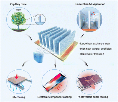
Herein, we came up with a high heat dissipation strategy and designed a composite heat sink (CHS) based on a multi-scale porous hydrogel. As illustrated in Scheme 1, the porous hydrogel was prepared by a high internal phase emulsion (HIPE) route and attached to the fin during polymerization. High heat flux cooling was realized by the combination of water evaporation with heat convection. The fin enhances the heat exchange capacity because of the increased evaporation surface area. More importantly, the hydrogel has a multi-scale porous structure, showing relatively good water absorption and storage capacity. By inserting a superhydrophilic non-woven fabric between the porous hydrogel and the fin, water can be passively transported and replenished by the capillary action. In this work, the influence of the polymerization formula on multi-scale porous structure and the optimal design of the fin were studied systematically. The as-prepared CHS showed heat dissipation ability comparable to forced air convection without energy consumption. Furthermore, it has good stability and long-term performance, which exhibits application prospects in heat dissipation and temperature control of thermoelectric devices, solar photovoltaic panels, and other high heat flux electronic components.
2. Results and discussion
2.1 Fabrication and characterization of the multi-scale porous hydrogel
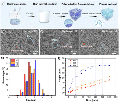
The porous hydrogel was prepared by the HIPE route, and the fabrication process is illustrated in Fig. 1a. Acrylamide (AM) monomer and N–N′ methylene diacrylamide crosslinker were first dissolved in water. Tween 80 and SiO2 nanoparticles acted as emulsifiers and stabilizers, respectively. The high internal oil-in-water emulsion was formed by adding cyclohexane drop by drop. After the potassium persulfate initiator and tetramethylenediamine catalyst were added to the emulsion, AM could be cross-linked to form the polymer. Due to the presence of the inner phase cyclohexane, the hydrogel formed micrometer-scale pores. After draining cyclohexane, a PAM porous hydrogel was prepared. In general, a hydrogel with only SiO2 nanoparticles exhibits a closed-cell structure, which is not conducive to the water rehydration process. Studies demonstrated that surfactants can reduce interfacial tension and viscosity of the continuous phase, resulting in a thinner droplet film than Pickering-HIPE without surfactants. The thin droplet film makes it easier to form pore throats between the pores, leading to an open-cell structure.29,30 Therefore, the surfactant Tween 80 and the stabilizer SiO2 nanoparticles were chosen to form the multi-scale porous structure in the hydrogel, which is able to achieve self-hydration function during the cooling process.The hydration capacity of the porous hydrogel is affected by the capillary force, which depends on the pore size of the micropores. By adjusting the amount of SiO2 nanoparticles, the diameter of pores and pore throats could be changed to realize the regulation of the capillary force. To optimize the water absorption and storage capacity of the porous hydrogel, the influence of different stabilizer concentrations on the porous structure was analyzed. Samples with different SiO2 concentrations were prepared and named H1 (2%), H2 (3%) and H3 (4%). Fig. 1b–d are the SEM images of the samples, displaying the multi-scale porous structure of the open-cell pores. Most of them have small pores with pore sizes less than 10 μm, and a small number of large pores with pore sizes of tens of micrometers are distributed. The hydration height and speed are considerably affected by the capillary force; larger pores can decrease the resistance to water flow in the microchannels, but the capillary force of the hydrogel decreases while smaller pores have the opposite behavior. Due to the multi-scale porous structure of the samples, both the water absorption capacity and absorption speed of the porous hydrogels should be considered. Compared with H1 and H2, sample H3 has a more uniform pore size distribution. Besides, the ratio of the pore throat diameter to the pore diameter of H3 is larger, which means the difference between the two diameters is smaller. The diameter of the pore throat is the main factor affecting the water permeability of porous structures,31 and the increase of the pore throat diameter is conducive to increasing permeability and reducing the flow resistance of water. Thus, a relatively larger pore throat diameter is crucial for the water absorption capacity in the cooling system. Fig. 1e shows the size distribution of the porous hydrogel samples. With the increase in the concentration of the stabilizer SiO2 nanoparticles, the largest proportion of the pore size increases, and the pore size distribution becomes more concentrated. The pores of 2–5 μm in H3 account for 80%, and the pores of about 3 μm account for more than 30%, which is higher than that of H1 and H2. The uniform size distribution ensures rapid absorption speed and stable absorption capacity. The water absorption capacity test further proved the aforementioned discussion (Fig. 1f and Fig. S1, ESI†). The results indicate that sample H3 with a proper size distribution and relatively large pore throat diameter has much higher capillary force and lower flow resistance, which makes its water absorption performance much better. The multi-scale porous hydrogel with excellent absorption capacity lays the foundation for the efficient heat dissipation of the CHS.
2.2 Preparation of the CHS composed of porous hydrogel and fin
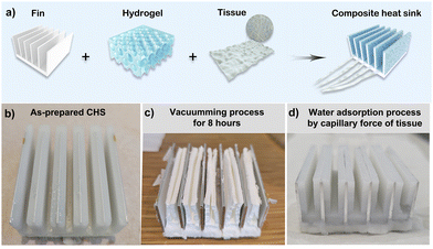
The fabrication process of the CHS is demonstrated in Fig. 2a. PTFE was used as the mold because of its excellent hydrophobicity, which facilitates the release of CHS. The PAM porous hydrogel was cross-linked between the mold and the fin. Besides, the non-woven fabric was fixed on the base of the fin to achieve rapid and stable hydration. After the mold was released, the CHS was prepared. The fin is evenly wrapped by a layer of porous hydrogel as shown in Fig. 2b. To test the strength of the hydrogel and the adherence between the hydrogel and the fin, a vacuum-rehydration experiment was carried out. The results are illustrated in Fig. 2c–d. The water in the hydrogel was completely extracted after it was placed in a vacuum environment for 8 h. Fig. 2c is the digital photo of the dehydrated CHS. The dehydrated CHS retains good morphology with little change in volume due to the porous structure and good strength of the hydrogel. During the rehydration procedure, the non-woven fabric was immersed in a water source, and water was quickly pumped by capillary force and rehydrated into the porous hydrogel. The photo of the rehydrated CHS is shown in Fig. 2d, which proves that the swelling hydrogel still adheres well to the fin after the vacuum-rehydration process. The hydrophilic wettability of the aluminum fin provides a good bonding force, which is beneficial for reducing thermal contact resistance and realizing excellent thermal conductivity.2.3 Simulation and structure optimization of the CHS
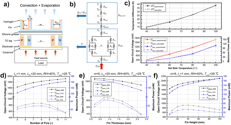
The influence of the fin structure parameters on the heat dissipation performance of the CHS was further analyzed by simulation, and reasonable structure design parameters were obtained. The power generation of TEG was used as the application scenario. Fig. 3a shows the working principle of TEG and the schematic of heat dissipation with the CHS. According to the structure, the thermal resistance model was established by energy conservation relations as shown in Fig. 3b. The corresponding detailed calculation process is explained in the ESI† (Fig. S2 and S3). The heat dissipation capacity and power generation performance of the generator were calculated with different CHS parameters. The TEG is a common commercial 127-pair device with a size of 4 cm × 4 cm, and the footprint area of the heat sink is the same as the TEG. To verify the accuracy of the model, an experimental system with the same parameters was designed, and therefore the simulation results could be compared with the experimental results. As shown in Fig. 3c, the simulation values of the temperature difference between the two sides of the TEG, the open-circuit voltage, and the maximum output power are in good agreement with the experimental values (deviation < 5%). The results show that the simulation model has high calculation accuracy and can optimize the structural parameters of the CHS.According to the simulation model, the performances of the TEGs with different CHS parameters were predicted. The number of fins, fin thickness, and fin height were optimized. The hot side temperature of the TEG was fixed at 100 °C, the ambient temperature was 28 °C, and the relative humidity was 50%. The influence of the conventional fin heat sink (FHS) and the CHS on power generation performance was calculated to compare the heat dissipation capacity. The calculation results are illustrated in Fig. 3d–f. For FHS, there is an optimal solution for the number of fins; more fins mean an increase of the heat dissipation are as well as the reduction of fin spacing, which will impair the natural convection heat transfer coefficient. Because the main heat dissipation mode of the FHS is natural convection heat transfer, the contradictory relationship makes the heat dissipation capacity the best when the number of fins is 7–8. For the CHS, heat transfer mainly depends on the latent heat of the evaporation of water, which is affected little by the fin spacing. Therefore, CHS heat dissipation capacity is positively correlated with the number of fins. Considering the processing cost and the convenience of production, the number of fins of CHS is determined as 8. When there are 8 fins, the power generation of the TEG with the CHS is about 3.8 times compared with that of the TEG with the FHS (Fig. 3d). Similarly, the effects of the fin thickness and height were analyzed. Both the fin temperature uniformity and the convective heat dissipation increase with the CHS fin thickness increasing (within 0.7 mm). However, the surface area of the hydrogel decreases and the evaporation heat dissipation is affected, so the total heat flow shows a decreasing trend (Fig. 3e). As a result, the thickness of the fins is designed as 0.7 mm. As for the height of the fins, although the heat dissipation performance improves with the height of the CHS, the height should be designed within a reasonable range (Fig. 3f). Higher fin height will make it more difficult to prepare the hydrogel and fit the hydrogel with fins. Besides, it is harder to maintain the balance of evaporation and water hydration in the situation of a large heat flux source, which will lead to the failure of the CHS. Therefore, the height of the CHS fins is recommended within the range of 20–40 mm. To clarify the parameters’ range that can guarantee the validity of the CHS, the influence of ambient temperature and humidity on CHS heat dissipation performance was analyzed (Fig. S4, ESI†). CHS can work normally when the relative humidity is 0–100%, and the lower the humidity, the better the heat dissipation performance. With the heat source temperature of 100 °C, the power generation is reduced by 23.7% when the relative humidity is 100% compared to that at a relative humidity of 0. The output power is about 102 mW at this time, which is greatly improved compared with the output of 30–40 mW when the FHS heat dissipation is adopted (Fig. 3d–f). When the ambient temperature ranges from 0–40 °C, the higher the ambient temperature, the worse the heat dissipation performance. Even at a high ambient temperature of 40 °C, TEG power generation with CHS is 2–3 times better than that with FHS. Note that to keep the water from freezing, CHS should be used in an environment above the freezing temperature.
2.4 Characterization and cooling performance of the CHS
The as-prepared CHS has excellent heat dissipation performance, which exhibits a good application prospect. To evaluate the heat dissipation capacity of the CHS, the heat transfer coefficient of the CHS was calculated by the heat transfer rate and temperature distribution of the simulation results. Fig. 4a shows the heat transfer coefficient under different working conditions. The heat transfer coefficient of the natural convection is about 0–25 W m−2 K−1, and the natural convection heat transfer coefficients of 5–10 W m−2 K−1 are more common in daily convection. The heat transfer coefficient of CHS is approximately 60 W m−2 K−1, which is 6–10 times higher than that of the natural convection. The cooling capacity of the CHS is equivalent to that of the forced air cooling but without extra energy consumption. By analyzing the composition of the heat transfer rate, it was found that the enhanced heat transfer was mainly the latent heat of evaporation (Fig. 4b). The heat flow dissipated by evaporation accounts for more than 70% of the total heat flow, which is difficult to realize by natural convection. As the working temperature increases, the evaporation heat flow increases. As long as the water rehydration capacity of the CHS can meet the demand of evaporation, the CHS can operate steadily and maintain good heat dissipation performance.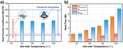 | ||
| Fig. 4 (a) Heat transfer coefficients of the CHS at different hot side temperatures. (b) Heat flow composition of the CHS. | ||
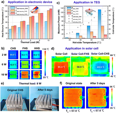
Furthermore, the performances of the CHS in electronic devices, TEG, and solar cell cooling are characterized. FHS and heat sink with hydrogel only (HHS) were used as controls. The results are compared and illustrated in Fig. 5a–d. For the heat dissipation of electronic devices with high heat flux, the influence of different heat sinks on the operating temperature under the same thermal load was studied. The heat load was controlled between 2 and 10 W and the heat source area was determined in 4 cm × 4 cm. The temperature of the heat source with different heat sinks was recorded using an infrared camera (Fig. 5b), and the temperature results are illustrated in Fig. 5a. It is clear that the CHS could keep the heat source temperature at about 60 °C by convection and evaporation, while the temperatures of the other heat sinks were maintained above 100 °C at 10 W of heat load. The results demonstrate the excellent performance of CHS in the temperature control of electronic products. For the heat dissipation of TEG, the CHS is able to cool the cold-side effectively when the temperature of the hot-side is in the range of 40–100 °C (Fig. 5c), which can help the TEG to establish a relatively larger temperature difference. The large temperature difference makes the maximum power of TEG increase 4–10 times compared to that of the controls under the same working conditions. For the heat dissipation of the solar cell, a solar cell was placed under solar irradiation of about 1180 W m−2, and the temperature of the solar cell under different heat dissipation conditions was measured using an infrared camera (Fig. 5d). The temperature of the solar cell without heat sink was 65.4 °C. When FHS was used for heat dissipation, the temperature of the solar cell could be controlled at 58.0 °C. For CHS, the surface temperature was further reduced by 22.1 °C compared with that of solar cells without the heat sink. It is obvious that the CHS can reduce the surface temperature of the solar cells effectively, which is of great significance for the life and efficiency of solar cells. Moreover, the CHS can be rehydrated through the capillary force of non-woven fabric and porous hydrogel. To confirm its stability, a long-term stable test was conducted (Fig. 5e and f). The heat load of the heat source was controlled at 8 W, and the ambient temperature was 25 °C. After continuous operation for 5 days, the hydrogel was still well moisturized and closely fitted to the fins without any obvious change (Fig. 5e). Fig. 5f shows the temperature distribution on the surface of the heat source. It can be seen that the surface temperatures of the heat source were controlled below 57 °C stably at the original state and after 5 days of continuous operation. Thus, the porous structure of non-woven fabric and hydrogel can realize a stable and rapid water replenishment process, which makes the CHS a suitable candidate for the promising application in the field of high heat flux dissipation.
3. Conclusions
In summary, a high heat dissipation strategy is proposed and applied in a passive CHS by fabricating porous hydrogel on the surface of the fin. Since the heat exchange capacity of the CHS is greatly enhanced due to the evaporation latent heat and the increase of heat exchange area, high heat flux dissipation can be realized. The porous hydrogel was fabricated via a simple HIPE method, which could reduce the hydrogel volume variation during the polymerization process and lead to low thermal contact resistance. Besides, by adjusting the ratio of stabilizer to emulsifier, a multi-scale porous structure that consists of both proper pores and pore throats was prepared. Moreover, the heat transfer coefficient of the CHS can reach 60 W m−2 K−1 without extra energy consumption, which is comparable to that of forced air convection. When this CHS was utilized in electronic devices with a high heat load of over 10 W, the surface temperature could be controlled at about 60 °C. While for the ordinary fin, the temperature increased above 100 °C. When it came to the TEG field, it was able to improve the electricity output performance by 4–10 times. As for solar cell cooling, the temperature of the solar cell with CHS could be controlled at 43.3 °C under solar irradiation of about 1180 W m−2. All the aforementioned results have demonstrated the good heat dissipation performance of the CHS. It is worth noting that a passive rehydration process can be achieved via capillary structures of the non-woven fabrics. The CHS was able to stably work for five days under the heat load of 8 W, indicating its stability. In conclusion, the CHS has the potential to be applied in the fields of high heat flux heat dissipation, thermoelectric power generation, thermoelectric refrigeration and solar photovoltaic power generation as a result of the zero energy consumption property.4. Experimental
4.1 Characterization and cooling performance of the CHS materials and instruments
Acrylamide, Tween 80, and SiO2 nanoparticles (Sinopharm Chemical Reagent Beijing Co., Ltd., Beijing, China), N–N′ methylene diacrylamide and cyclohexane (Shanghai Macklin Biochemical Technology Co., Ltd., Shanghai, China), potassium persulfate and tetramethylenediamine (Aladdin Industrial Inc., Shanghai, China) were used as-received. A scanning electron microscope (Sigma 300 HV, Carl Zeiss, Germany) was utilized to characterize the surface morphology. The size distribution of the porous hydrogel was measured using an automatic mercury porosimeter (Macautopore V 9600, Micromeritics Instrument Corporation, America).4.2 Fabrication of the porous hydrogel
The porous hydrogel was prepared by the HIPE route. First, a certain amount of monomer acrylamide (4 g) and crosslinker N–N′ methylene diacrylamide (0.4 g) were dissolved in water (20 mL) at ambient temperature. Then, quantitative emulsifier Tween 80 (1.2 g) and stabilizer SiO2 nanoparticles were added to the solution and stirred for several minutes. After that, the inner phase cyclohexane (60 ml) was added drop by drop until a stable oil-in-water emulsion was formed. After the initiator potassium persulfate (0.2 g) and catalyst tetramethylenediamine (20 μl) were added to the emulsion, AM was cross-linked to form the PAM porous hydrogel.4.3 Fabrication of the CHS
First, the PTFE mold was machined according to the fin size and the thickness of the designed hydrogel. Then, the non-woven fabric was fixed on the base of the fin to achieve rapid and stable hydration. After that, the fin fixed with non-woven fabric was placed in the PTFE mold, and the prepolymer emulsion was poured into the mold before the AM cross-linking occurred. Finally, the mold was released carefully after the cross-linking was completed.4.4 Cooling performance of the CHS in TEG
The output of the TEG (maximum power and open-circuit voltage) was characterized using a 2400 source meter from Keithley Instruments. The temperature was measured using a thermocouple (Omega Company) and recorded by a paperless recording instrument (SIN-R9600, Hangzhou SinoMeasure Automation Technology Co., Ltd). The temperature of the TEG hot-side was controlled using a semiconductor temperature control system with an accuracy of ±0.1 K (TLTP-FW-TEC2410D, Wuhan Tailunte Century Technology Co., Ltd). Three heat sinks were employed under the same condition. The fin heat sink, which was not equipped with the porous hydrogel, and the heat sink using a piece of hydrogel without fins were used as the control samples. The environmental temperature and relative humidity were monitored using a thermohygrometer.4.5 Cooling performance of the CHS in the Simulated electronic device
The electronic device was simulated with a film electronic heater. The power of the heater was set in the range of 125–625 mW cm−2 using a DC power supply over an area of 4 cm × 4 cm. The temperature of the heater was measured using an infrared camera (T650sc, Teledyne FLIR). As with the TEG measurements, three heat sinks were used to compare the cooling effects.4.6 Cooling performance of the CHS in a solar cell
The solar cell (CNC60X60-2, starsolar) was 6 cm × 6 cm in size and was placed outside in the sun. The surface temperature of the solar cell was measured using an infrared camera (T650sc, Teledyne FLIR). Solar density was measured using a radiometer (YJ-TR200, Wuhan Jiuqing Meteorological Technology Co., Ltd). The temperatures of the solar cell without a heat sink and with a heat sink of FHS were tested as controls.Conflicts of interest
There are no conflicts to declare.Acknowledgements
This work was supported by the National Key Research and Development Program of China (Grant No. 2018YFA0702100), the National Natural Science Foundation of China (Grant No. 52003015), the Zhejiang Provincial Natural Science Foundation of China (Grant No. LZ23E020004), the National Natural Science Foundation of China (Grant No. 52102202), the Zhejiang Provincial Key Research and Development Program of China (Grant No. 2021C01026) and the Leading Innovative and Entrepreneur Team Introduction Program of Zhejiang (2020R01007).References
- G. Schierning, Nat. Energy, 2018, 3, 92–93 CrossRef CAS.
- W. Ren, Y. Sun, D. Zhao, A. Aili, S. Zhang, C. Shi, J. Zhang, H. Geng, J. Zhang, L. Zhang, J. Xiao and R. Yang, Sci. Adv., 2021, 7, eabe0586 CrossRef CAS PubMed.
- J. Hu, Z. Wei, B. Ge, L. Zhao, K. Peng and Z. Shi, J. Mater. Chem. A, 2023, 11, 10727–10737 RSC.
- Z. W. Chen, Z. Z. Jian, W. Li, Y. J. Chang, B. H. Ge, R. Hanus, J. Yang, Y. Chen, M. X. Huang, G. J. Snyder and Y. Z. Pei, Adv. Mater., 2017, 29, 1606768 CrossRef PubMed.
- T. Li, X. Zhang, S. D. Lacey, R. Y. Mi, X. P. Zhao, F. Jiang, J. W. Song, Z. Q. Liu, G. Chen, J. Q. Dai, Y. G. Yao, S. Das, R. G. Yang, R. M. Briber and L. B. Hu, Nat. Mater., 2019, 18, 608–613 CrossRef CAS PubMed.
- O. I. Ibeagwu, Energy, 2019, 180, 90–106 CrossRef.
- M. J. Liao, Z. He, C. P. Jiang, X. A. Fan, Y. W. Li and F. S. Qi, Appl. Therm. Eng., 2018, 133, 493–500 CrossRef.
- W. He, R. Guo, H. Takasu, Y. Kato and S. X. Wang, Energy, 2019, 175, 1153–1163 CrossRef.
- T. Pujol, I. T’Jollyn, E. Massaguer, A. Massaguer, I. R. Cozar and M. De Paepe, Appl. Therm. Eng., 2023, 221, 119866 CrossRef CAS.
- B. Chen, J. Song, X. Dai, Y. Liu, P. N. Rudd, X. Hong and J. Huang, Adv. Mater., 2019, 31, 1902413 CrossRef PubMed.
- G. Besagni, L. Croci, R. Nesa and L. Molinaroli, Renew. Energ, 2019, 132, 1185–1215 CrossRef.
- M. Hasanuzzaman, A. Malek, M. M. Islam, A. K. Pandey and N. A. Rahim, Sol. Energy, 2016, 137, 25–45 CrossRef.
- A. E. Bergles, Heat Mass Transfer, 2011, 47, 1001–1008 CrossRef.
- X. Wu, Z. Wu, Y. Wang, T. Gao, Q. Li and H. Xu, Adv. Sci., 2021, 8, 2002501 CrossRef CAS PubMed.
- E. Bellos, C. Tzivanidis and D. Tsimpoukis, Appl. Therm. Eng., 2018, 137, 669–677 CrossRef.
- H. Moon, K. Boyina, N. Miljkovic and W. P. King, Int. J. Heat Mass Transfer, 2021, 177, 121510 CrossRef CAS.
- X. Li, W. Xie and J. Zhu, Adv. Sci., 2022, 9, 2104181 CrossRef CAS PubMed.
- S. Chang, Y. chen, D. Wan and H. Chen, J. Mater. Chem. A, 2023, 11, 15183–15195 RSC.
- J. Liang, J. Wu, J. Guo, H. Li, X. Zhou, S. Liang, C. Qiu and G. Tao, Nat. Sci. Rev., 2023, 10, nwac208 CrossRef CAS PubMed.
- R. Kiflemariam and C. X. Lin, Int. J. Therm. Sci., 2015, 94, 193–203 CrossRef.
- A. Bar-Cohen, R. Bahadur and M. Iyengar, Energy, 2006, 31, 579–619 CrossRef CAS.
- M. Huang, M. Yang, X. Guo, C. Xue, H. Wang, C. Ma, Z. Bai, X. Zhou, Z. Wang, B. Liu, Y. Wu, C. Qiu, C. Hou and G. Tao, Prog. Mater. Sci., 2023, 137, 101144 CrossRef.
- Y. Wang, T. Wang, J. Liang, J. Wu, M. Yang, Y. Pan, C. Hou, C. Liu, C. Shen, G. Tao and X. Liu, Mater. Horiz., 2023, 10, 5060–5070 RSC.
- M. A. Hanlon and H. B. Ma, J. Heat Trans-T. ASME, 2003, 125, 644–652 CrossRef.
- J. Yang, Y. C. Zhou, L. Y. Yang, C. P. Feng, L. Bai, M. B. Yang and W. Yang, Adv. Funct. Mater., 2022, 32, 2200792 CrossRef CAS.
- Z. C. Wei, Y. B. Wang, C. Y. Cai, Y. X. Zhang, S. Guo, Y. Fu and S. C. Tan, Adv. Funct. Mater., 2022, 32, 2206287 CrossRef CAS.
- S. R. Pu, J. Fu, Y. T. Liao, L. R. Ge, Y. H. Zhou, S. L. Zhang, S. L. Zhao, X. W. Liu, X. J. Hu, K. Liu and J. Chen, Adv. Mater., 2020, 32, 1907307 CrossRef CAS PubMed.
- F. Ni, P. Xiao, C. Zhang, W. Zhou, D. P. Liu, S. W. Kuo and T. Chen, Adv. Mater., 2021, 33, 2103937 CrossRef CAS PubMed.
- S. D. Kimmins and N. R. Cameron, Adv. Funct. Mater., 2011, 21, 211–225 CrossRef CAS.
- V. O. Ikem, A. Menner, T. S. Horozov and A. Bismarck, Adv. Mater., 2010, 22, 3588–3592 CrossRef CAS PubMed.
- R. Foudazi, React. Funct. Polym., 2021, 164, 104917 CrossRef CAS.
Footnotes |
| † Electronic supplementary information (ESI) available. See DOI: https://doi.org/10.1039/d3ma00970j |
| ‡ These authors contributed equally to this work. |
| This journal is © The Royal Society of Chemistry 2024 |

