 Open Access Article
Permeation properties and hydrothermal stability of allylhydridopolycarbosilane (AHPCS)-derived silicon carbide (SiC) membranes†
Gusni
Sushanti
 ,
Daiki
Tanabe
,
Khuat
Thi Thu Hien
,
Norihiro
Moriyama
,
Daiki
Tanabe
,
Khuat
Thi Thu Hien
,
Norihiro
Moriyama
 ,
Hiroki
Nagasawa
 ,
Masakoto
Kanezashi
 and
Toshinori
Tsuru
 *
*
Department of Chemical Engineering, Graduate School of Advanced Science and Engineering, Hiroshima University, 1-4-1 Kagami-yama, Higashi-Hiroshima 739-8527, Japan. E-mail: tsuru@hiroshima-u.ac.jp
First published on 6th February 2024
Abstract
Among various membrane materials used for gas separation, silicon carbide (SiC) is promising because of its structural stability and mechanical strength. In this study, allylhydridopolycarbosilane (AHPCS) was used as a precursor for SiC membranes to improve gas permeance and hydrothermal stability. The membrane was prepared by coating AHPCS sols on a SiO2–ZrO2 intermediate layer as the top layer, followed by firing at 500–800 °C. The highest H2 permeance of (2.3–3.0) × 10−6 mol m−2 s−1 Pa−1 with H2/N2 of 10–30 and a H2/SF6 permeance ratio higher than 1000 was obtained on AHPCS-derived SiC membranes fired at 500–700 °C. The AHPCS-derived SiC membranes were then subjected to hydrothermal treatment. After being exposed to steam, the N2 permeance decreased from 2.4 × 10⁻⁸ and reached stable permeances of ∼3 × 10⁻⁹ mol m−2 s−1 Pa−1. In the separation of binary mixtures of H2O/N2 at 400 °C, the AHPCS membrane showed an excellent water selectivity, and permeance ratio for H2O/N2 of approximately 100, with an H2O permeance of (5.5–8.0) × 10−7 mol m−2 s−1 Pa−1. The temperature dependence of gas permeance in binary mixtures was measured in the range of 200–400 °C. The AHPCS-derived SiC membranes are promising materials for future applications in high temperature dehydration processes.
Introduction
Membranes for gas separation have attracted considerable interest from both industry and academia, and membrane-based gas separations involving gaseous media such as air separation, hydrogen purification, natural gas purification, H2/N2 separation and CO2 capture have developed immensely in recent years.1,2 In general, permeance and selectivity (or separation factors) are two common and fundamental characteristics that describe membrane performance. An ideal membrane should exhibit a high permeance and selectivity. A higher permeance reduces the membrane area required to separate a certain amount of gas, thereby reducing the membrane investment costs. Higher selectivity can result in high-purity products. Based on the current requirements for advanced membrane technology, the successful application of membranes in gas separation processes depends not only on the high permselectivity of the membrane but also on the selection of membrane materials with thermal, hydrothermal, chemical, and mechanical stabilities.3Inorganic membranes have many advantages, such as high chemical, thermal, and mechanical stability. Inorganic membranes have been fabricated from crystalline materials such as zeolites or amorphous materials such as silica and carbon. In particular, amorphous inorganic membranes such as silica (SiO2) and silicon carbide (SiC)-based membranes have a pore size distribution that may decrease the selectivity, but possess the great advantage that these structures are known to reduce defects due to flexibility.4 SiO2 derived membranes have high H2 permeance in dry gas. However, membrane stability under hydrothermal conditions is a critical issue that must be addressed.5 Tsuru et al.6 fabricated cobalt-doped silica membranes, which showed stable H2 permeance of 1.8 × 10⁻⁷ mol m−2 s−1 Pa−1 with H2/N2 permeance ratios of approximately 730 and a H2O/H2 permeance ratio of 5–40 under a steam pressure of 300 kPa, and temperature of 300–500 °C. Metal doping of silica membranes has been confirmed to improve their hydrothermal stability. Notably, the silica and metal-doped silica membranes exhibited H2 selectivity over H2O.
Recently, H2O recovery from steam at high temperatures, such as flue gas, has been proposed. Moriyama et al. reported steam recovery via nano-porous and sub-nanoporous bis(triethoxysilyl)ethane (BTESE)-derived organosilica membranes, which reached a maximum water flux of 73 kg m−2 h−1 at a transmembrane pressure of 300 kPa during vapor permeation.7 Binary humid gas separation (H2O/H2 and H2O/N2) was evaluated at temperatures ranging from 80–200 °C under feeds of water mole fractions ranging from 0.1–0.9. The highest levels of water permeation flux, permeance, and permeance ratios of H2O/N2 were 37 kg m−2 h−1, 5.5 × 10⁻⁶ mol m−2 s−1 Pa−1, and infinity (>6700), respectively, at 150 °C, when the partial pressure difference of water across the membrane was 107 kPa.8 Interestingly, the BTESE-derived membranes showed H2O selectivity over H2, which was the opposite of that of silica and metal-doped silica. However, BTESE-derived organosilica membranes can be used at medium temperatures (100–300 °C) since they will be decomposed at high temperatures.
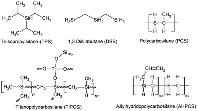
Silicon carbide (SiC) is a promising material because of its excellent structural stability. In addition, SiC membranes are applicable under harsh conditions, such as high temperatures and corrosive chemicals.9 SiC-derived membranes were prepared using two methods: chemical vapor deposition (CVD) and the sol–gel method.10 Various precursors have been used for the fabrication of SiC-derived membranes (Fig. 1). Tsotsis et al. reported various precursors including triisopropylsilane (TPS) and 1,3-disilabutane (DSB). The TPS membranes exhibited good hydrothermal stability and selectivity. Conversely, the DSB membrane showed high permeance but was found to be unstable when exposed to high steam temperatures (under vapor at 400 °C and partial pressure of 100–300 kPa).11,12 The possible reason for this result is that their SiC membranes introduced excess O and formed many Si–O–Si bonds, rather than Si–C during hydrothermal treatment.1 Polymer-to-ceramic precursors such as polycarbosilanes (PCS) resulted in a PCS-derived SiC membrane with H2/N2 selectivity of 13 and H2 permeance of 9 × 10⁻⁸ mol m−2 s−1 Pa−1 at 500 °C.13,14 Iwamoto et al. reported polycarbosilane (PCS)-derived membranes, which showed H2 permeance of 7.7 × 10⁻⁸ mol m−2 s−1 Pa−1 with H2/N2 selectivity of 26 under saturated humidity at 50 °C.15 Wang et al.16 fabricated PCS-derived membranes and reported H2 permeance of 1–2 × 10⁻⁶ mol m−2 s−1 Pa−1 at 500 °C with H2/N2 selectivity of 31. However, their performance under hydrothermal treatment has not yet been reported. A polydimethylsilane (PMS)-derived SiC membrane showed H2 permeance of 2.7 × 10⁻⁹ mol m−2 s−1 Pa−1, and H2/N2 selectivity of 20.17 The PMS-derived membrane was destroyed under hydrothermal treatment at 300–500 °C and low-total pressure of 1.33 kPa with low-partial pressure water vapor of 0.023 kPa.18 Most SiC membranes exhibit low gas permeance, presumably because of their dense structures with smaller pores. Thus, Ti-doped SiC membranes were prepared as polytitanocarbosilane (TiPCS)-derived membranes but still showed a low H2/N2 selectivity of 10.19 The addition of Ti to the SiC membranes did not enhance their selectivity.
Another polymer-to-ceramic precursor was allylhydridopolycarbosilane (AHPCS). AHPCS-derived membranes fabricated via slip casting with dip coating showed H2/CO2 selectivity of 42–96 and H2/CH4 selectivity of 29–78.10 Our group also reported AHPCS pre-crosslinking at 150–200 °C under N2, increased the size of the colloidal sol in a toluene solution, and consequently improved the gas permeation properties.20 AHPCS-derived membranes are promising due to high H2 permeance around 10−7–10−6 mol m−2 s−1 Pa−1, H2/N2 selectivity of 16–22, and H2/SF6 selectivity higher than 10![[thin space (1/6-em)]](https://www.rsc.org/images/entities/char_2009.gif) 000.20 These improvements were primarily applicable in dry systems. Although SiC is promising for microporous membranes, the hydrothermal stability of SiC has never been evaluated in detail as far as the authors ascertain. Hence, the novelty of this study lies in the detailed evaluation of both membrane permeation properties and the materials characterization under HT as will be discussed later. AHPCS-derived membranes showed excellent stability and high H2O permselectivity over N2, leading to the proposal of the innovative concept of high-temperature steam recovery using SiC membranes.
000.20 These improvements were primarily applicable in dry systems. Although SiC is promising for microporous membranes, the hydrothermal stability of SiC has never been evaluated in detail as far as the authors ascertain. Hence, the novelty of this study lies in the detailed evaluation of both membrane permeation properties and the materials characterization under HT as will be discussed later. AHPCS-derived membranes showed excellent stability and high H2O permselectivity over N2, leading to the proposal of the innovative concept of high-temperature steam recovery using SiC membranes.
AHPCS membranes were prepared in 2 stages: AHPCS pre-crosslinked precursor was coated and fired at a temperature range of 500–800 °C under a N2 atmosphere, followed by hydrothermal treatment. We evaluated the permeation properties and hydrothermal stabilities of the AHPCS-derived membranes. Hydrothermal treatment was performed at steam temperatures of 400 °C with an H2O partial pressure of 125 kPa. Moreover, the characterization, including Fourier transform infrared (FTIR), thermogravimetric analysis (TGA), and energy-dispersive spectra (EDS), of the AHPCS membrane before and after hydrothermal treatment is also discussed.
Experimental
Fabrication of AHPCS-derived membrane
Porous α-Al2O3 tubes (average pore diameter: 1 μm, porosity: 50%, outer diameter: 10 mm, inner diameter: 8 mm, tube length: 10 cm, supplied by Nikkato, Co, Ltd, Japan) were used as supports. The procedure used to modify the supports was similar to that used in our previous study.20 Two types of α-alumina particles (average particle size: 0.2 and 2 μm) using 10 wt% SiO2–ZrO2 (Si/Zr = 5/5) colloidal sol as a binder were coated onto the outer surface of the porous support, which was followed by calcination at 700 °C under air for 15 min. Subsequently, colloidal sol of 0.5 wt% SiO2–ZrO2 (Si/Zr = 5/5) was coated onto the particle layer and calcined at 700 °C for 15 min to form an intermediate layer with an average pore size of 1–2 nm, which can minimize the formation of defects in the topmost AHPCS separation layers.5,21,22AHPCS (labelled SMP-10, Starfire Systems Inc, USA) was used as the SiC precursor. The molecular structure of AHPCS is shown in Fig. 1. SMP-10 is a clear yellow viscous liquid with a density of 0.998 g cm−3. Firstly, the fresh AHPCS solution was thermally cured to pre-crosslink (PCL) at a temperature of 150 °C for 2 h under a N2 atmosphere. PCL induced the growth of the sol sizes and reduce the penetration of the AHPCS precursor into the intermediate layer.20 For coating the top layer of the AHPCS-derived membranes, the PCL-AHPCS solution was diluted with toluene as a solvent to 0.125 wt%. Then, it was coated onto the SiO2–ZrO2 intermediate layer, followed by firing at 500–800 °C for 1 h under N2 flow (500 mL min−1) with a heating rate of approximately 10 °C min−1. The coating-firing process was repeated four times to reduce the possibility of defects in the AHPCS-based top layer. AHPCS-derived membranes were fabricated by firing at temperatures of 500, 600, 700 and 800 °C, which hereafter will be referred to as M500, M600, M700, and M800, respectively. When multiple membranes are prepared, they are referred to as M###-#, where the first three and last digits indicate the firing temperature and membrane serial number, respectively.
Characterization of AHPCS-derived powders
AHPCS powders were obtained at various temperatures (500–800 °C) to understand the effect of temperature on structure evolution during polymer-to-ceramic transformation. The AHPCS solution was placed in an alumina boat and heated in a tube furnace under N2 flow for 6 h at different temperatures to convert liquid AHPCS into a solid powder. The powders prepared at 500, 600, 700, and 800 °C hereafter will be referred to as P500, P600, P700, and P800, respectively. It should be noted that all powders were prepared in the same environment (e.g., atmosphere and furnace) as the membranes to ensure as much consistency as possible. During the above process, the furnace was heated at 10 °C min−1 and cooled to room temperature naturally. The powdered samples were used for FTIR and EDS analysis. FTIR analysis was performed using an FTIR spectrometer (FT/IR-4600, JASCO Co, Japan) in transmittance mode for fresh AHPCS films coated on KBr plates, and in total attenuated reflection (ATR) mode for the powder samples. The chemical composition of the AHPCS powder was examined using a scanning electron microscope equipped with an EDS instrument (JCM 5700, JEOL, Japan). The membrane morphology was observed using scanning electron microscopy (SEM, S-4800, Hitachi, Japan).Evaluation of AHPCS-derived membranes
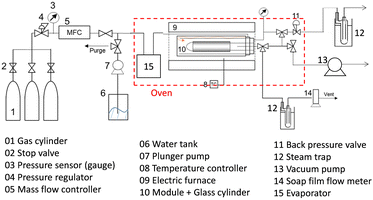
The permeance of a single gas with different kinetic diameters was measured using the experimental setup shown in Fig. 2. Single gases of He, H2, N2, and SF6 were fed to the outside of the cylindrical membrane at 200–400 °C and the permeate flow rate was measured using a soap film flow meter (HORIBA STEC, Japan). The permeance of the AHPCS membranes subjected to hydrothermal treatment was measured using the apparatus shown in Fig. 2. Water permeance was measured in a mixture of H2O/He and H2O/N2 under the total pressures of 250 kPa-a and a temperature of 400 °C. The feed flow rates of N2 or He and water vapor were fixed at 810 and 810 mL (STP) min−1, respectively. Water flux was measured by weighing a water trap (12), whereas the N2 or He flux was measured using a soap film flow meter (14) after water trapping. The water trap weight and feed-side pressure were recorded using a midi logger GL220-UM-801 (GRAPHTEC, Japan).The binary gas permeance is calculated using eqn (1), where P is permeance [mol m−2 s−1 Pa−1], Qperm is flow rate [mol s−1], and A is membrane area [m2]. Since the partial pressure of each component is not uniform along the membrane axial direction in a mixture system, the pressure difference is calculated using the partial pressure difference logarithmic mean, Δplm (eqn (2)), where Δpin and Δpout represent the partial pressure difference at the inlet and outlet of each gas. Further details can be found in the literature.23
 | (1) |
 | (2) |
| Δpin = pfeed − ppermeate | (3) |
| Δpout = pretentate − ppermeate | (4) |
Results and discussion
Permeation properties through AHPCS-derived membranes
The permeance of a single gas through an AHPCS-derived membrane was measured at a temperature of 200 °C. Single gas permeance is useful for evaluating the pore size distribution of membranes and is the simplest method for evaluating membrane quality.19 Fig. S1 (ESI†) shows single gas permeance at 200 °C as a function of the molecular size of permeating gases for AHPCS membranes fired in a temperature range from 500–800 °C. Generally, all membranes showed decreased permeances for large-sized gases, indicating typical molecular sieving properties. The H2/N2 selectivity ranged from 10–20 (Table S1, ESI†), with an excellent H2 permeance higher than 10−6 mol m−2 s−1 Pa−1 because H2/SF6 was more than 1000, the permeation of small molecules such as He and H2 was not affected by the existence of large pores, which allowed the permeation of large molecules such as CF4 and SF6. The H2 permeances of M500-1 and M600-1 were higher than those of He permeance, whereas M700-1 and M800-1 showed lower permeances for H2 than for He. These trends can be ascribed to the Knudsen diffusion for M500 and M600 and the molecular sieving properties for M700 and M800, which are further discussed below. It is important to note that in the current study, the AHPCS membrane is being extended to investigate its applicability under harsh conditions, specifically high-temperature steam environments.Fig. 3(a) summarizes the permeation properties, including the permeance of H2, N2, and SF6, and the selectivity of H2/N2 and H2/SF6 with respect to the firing temperature that offers a comprehensive overview of the pore formation mechanism. It should be noted that our current work (open symbol) and previous research20 (closed symbol) have confirmed the reproducibility of the fabrication of AHPCS-derived membranes. It should be noted that more than 15 different membranes are plotted in Fig. 3(a). The temperature dependence (200–400 °C) of the H2 permeances was also evaluated on the AHPCS-derived membrane and used to obtain the activation energy of H2 (Fig. S2, ESI†), as summarized in Fig. 3(a). Each membrane fired at the same temperature showed similar levels of permeance and selectivity for H2 and N2, indicating reasonable reproducibility of membrane fabrication. Notably, SF6 showed scattered permeance, because of the presence of pinholes. A small number of pinholes can be formed probably due to uneven shrinkage at high temperatures.20 SF6, which gas has a large molecule size (0.55 nm), is particularly sensitive to the presence of these pinholes. It is worth noting that the H2/SF6 selectivity is over 103 at firing temperatures between 300–700 °C. This indicates that high-quality membranes have a relatively small number of pinholes. As the firing temperature increases from 300–800 °C, the H2 activation energy declines first and then rises, while the H2 and N2 permeances show the opposite trend. Meanwhile, the H2/N2 selectivity decreased and then increased gradually with increasing firing temperature. The AHPCS-derived membrane shows high permeance and selectivity at 500–700 °C, which follows the molecular sieving properties. Furthermore, the H2 permeation properties of the AHPCS-derived membranes differed depending on the firing temperature. For AHPCS membranes fired at temperatures of 500–600 °C, as discussed in Fig. S1 (ESI†), the permeance of H2 is larger than that of He, which follows the Knudsen diffusion. On the other hand, AHPCS membranes fired at temperatures of 700–800 °C show higher permeance for He than H2, which follows the molecular sieving property. The surface morphology of M700 was characterized using FESEM, revealing a thin top layer of approximately 30 nm (Fig. S3, ESI†). This thin top layer has the potential to impart the resulting membrane with high gas permeability and molecular sieving properties. Diffusion through large-sized pores compared with the size of permeating gases is governed by Knudsen diffusion, where the transport rate of gas is inversely proportional to the square root of its molecular weight. Therefore, H2 of lower molecular weight diffuses faster than He of larger molecular weight.24 If the membrane pores are extremely small, comparable to the molecular size of the gas, then the permeation mechanism of gases is determined by molecular sieving, resulting in higher permeance for He than H2, since the kinetic diameters of He and H2 are 0.26 and 0.289 nm, respectively. The highest H2 permeance was obtained by firing the AHPCS membrane at 500–600 °C, and firing at 700 °C or higher temperature induces the shrinking of the pores, which increased friction of the permeation of gas molecules and caused the increase of the activation energy and the decrease of H2 permeance. The H2 activation energy decreased from 6.3 for M300 to 2.4 kJ mol−1 for M600, and the H2 permeance increased from ∼4.5 × 10⁻⁷ to ∼3.5 × 10⁻⁶ mol m−2 s−1 Pa−1. This is because the M300 networks consist of AHPCS polymer networks that are flexible and vibrate at high temperatures, whereas in the M500 and M600, flexible carbons, such as allyl groups decompose and generate a large amount of space, which increases the gas permeance, as schematically shown in Fig. 3b. Meanwhile, the activation energy for the M700 and M800 membranes increased 4.3–7.3 kJ mol−1 and the H2 permeance decreased to 2.5–7 × 10⁻⁷ mol m−2 s−1 Pa−1. It can be concluded that firing at 700 and 800 °C made the membrane networks denser with smaller pores (Fig. 3b). In addition, DTG analysis (Fig. S4, ESI†) shows that the weight residue decreased as the temperature increased and remained stable at each firing temperature, signifying a process of transformation such as densification.
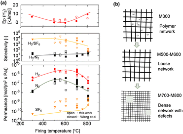 | ||
| Fig. 3 (a) Permeance of H2, N2, and SF6, selectivity of various gases at 200 °C, and H2 activation energy as a function of firing temperature. Open symbols are added in this work to our previous reported20 (closed symbols). (b) Schematic illustration of the network evolution of the AHPCS-derived membrane at different firing temperatures. | ||
Permeation properties of the AHPCS-derived membrane under hydrothermal conditions
After the single-gas permeation experiments, the permeation properties and hydrothermal stability under hydrothermal conditions were investigated. Fig. 4 shows the time course of permeance through the M600-1 membrane under the total and steam partial pressure of 250 and 125 kPa-a, respectively, at 400 °C. First, dry gas (He and N2) was fed into the membrane, and the permeance was measured to confirm steady values. Then, the H2O/N2 binary system was fed for 6 h followed by the H2O/He binary system for 6 h. This hydrothermal treatment (HT) procedure (dry He and N2, followed by H2O/N2 mixtures and then H2O/He mixtures) was repeated three times.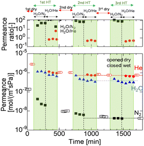 | ||
| Fig. 4 Time course of the N2, He and H2O permeance of the M600-1 membrane in a mixture of H2O/N2 and H2O/He (400 °C, feed: 250 kPa (abs) (water vapor 125 kPa), permeance: 100 kPa (atmosphere)). | ||
Fig. 4 shows that the N2 permeance dramatically decreased from the dry to the wet system in the 1st HT cycle, while the He and H2O permeances were relatively stable around ∼10−6 mol m−2 s−1 Pa−1. After 1 HT cycle, the N2 permeance dropped by one order of magnitude from 1.4 × 10⁻⁷ (before 1 HT) to 1.0 × 10⁻⁸ mol m−2 s−1 Pa−1 (after 1 HT), while the He permeance slightly decreased after 1 HT. The H2O/N2 permeance ratio gradually increased from 20 to 40. During the 2 HT cycle, the H2O/N2 permeance ratio increased to approximately 100, indicating high selectivity for water vapor. In the 3 HT cycle, He and N2 permeances in both the dry and wet systems almost reached stable values (detailed values in Table S2, ESI†). This trend can be explained by changes in surface structure and pore size during HT, as confirmed by FTIR analysis (Fig. 8). The AHPCS membrane surface was reacted with water vapor to form Si–OH, which possibly reduced the pore size (as shown schematically in Fig. S5, ESI†).
Fig. 5 shows single gas permeances at 200 °C for all AHPCS-membranes (M500, M600, M700, M800) before and after the 1st, 2nd, and 3rd HT, which were conducted at 400 °C. The pore size distribution was evaluated by measuring the single gas permeance at 200 °C to assess the membrane stability.25 The single gas permeance of fresh AHPCS membranes decreased dramatically after the 1st HT, and showed a slight decrease in the 2nd and 3rd HT reaching stable values under a water vapor of 400 °C. M500, M600, and M700 reached stability while retaining the molecular sieving property, implying that AHPCS membranes are resistant against water vapor at 400 °C. Interestingly, M600-1 showed a significant increase in H2/N2 selectivity after HT, from 26 to 85. This can be explained as follows: after HT the surface structure of the membrane changed, and the pore sizes became smaller, thus reducing N2 permeation. In addition, the permeances of small-sized gases (0.26–0.364 nm, i.e. He, H2, N2) of the M500-1, M600-1, and M700-1 membranes decreased while the M800-1 membrane gas permeance only slightly decreased after the hydrothermal treatment. This can be ascribed to an increase in stability owing to firing at high temperatures.
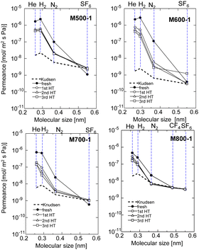 | ||
| Fig. 5 Single gas permeance at 200 °C before and after HT (1st HT, 2nd HT, and 3rd HT, all HT were conducted at 400 °C), through the AHPCS membrane fired at 500–800 °C. | ||
Fig. 6 shows the time course of H2O, N2, and He permeance in binary mixtures of H2O/N2 and H2O/He at 400 °C, which were obtained by removing the time course of the dry gas in Fig. 4. As the firing temperature increases, the fresh AHPCS membrane shows lower single-gas permeance for He and N2, which can be attributed to the shrinking of the pore sizes, as explained in Fig. S1(ESI†) and Fig. 3. All of the membranes showed that the He, N2, and H2O permeances decreased gradually under hydrothermal treatment. The permeance of H2O for M500-1 and M600-1 was similar to that of He, and both were two orders of magnitude higher than N2. On the other hand, M700-1 and M800-1 showed H2O permeances that decreased and became close to N2. Notably, the N2 permeance of M600-1 in Fig. 6b was significantly decreased from 1.3 × 10⁻⁷ to 3.3 × 10⁻⁹ mol m−2 s−1 Pa−1, while H2O decreased but kept a high permeance of 3.64 × 10⁻⁷ mol m−2 s−1 Pa−1, resulting in H2O/N2 of ∼100 and H2O/He of ∼1. He permeance remained approximately constant, while there is a notable reduction in N2 permeance. This decline in N2 permeance implies structural changes resulting from the generation and/or condensation of silanol groups during the hydrothermal process. As summarized in Table S3 (ESI)†, M500 and M600 showed high H2O/N2 with high H2O permeance of approximately a similar level. Consequently, additional testing of the long-term stability (∼50 h) and temperature dependency of the permeance was conducted using M550.
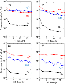 | ||
| Fig. 6 Time course of N2 and He permeance in a mixture with H2O during HT at 400 °C at (a) M500, (b) M600, (c) M700, and (d) M800. | ||
The permeance of He, H2, and N2 and the selectivity before and after HT as a function of the firing temperature of the AHPCS membranes are summarized for all the membranes evaluated in this study in Fig. 7. It should be noted that each set of gas permeance values corresponds to one membrane, including two membranes for M500, three membranes for M550, two membranes for M600, one membrane for M700 and one membrane for M800. In the dry system (before HT), as the firing temperature increases from 500 to 800 °C, the He permeance decreases from ∼2 × 10⁻⁶ to ∼5 × 10⁻⁷ mol m−2 s−1 Pa−1 and the N2 permeance decreases from 1 × 10⁻⁷ to 2 × 10⁻⁸ mol m−2 s−1 Pa−1. On the other hand, in the wet system (after HT), the He permeance decreased slightly, and the N2 permeance decreases significantly from 3 × 10⁻⁸ to 5 × 10⁻⁹ mol m−2 s−1 Pa−1 (Fig. 7a) owing to the molecular sieving property. Fig. 7b shows that the H2O permeance decreased gradually from 9.3 × 10⁻⁷ to 3.5 × 10⁻⁸ mol m−2 s−1 Pa−1 with an increase in firing temperature from 500 °C (M500) to 800 °C (M800), while the He/N2 of M500 and M600 was around 20, and that of M700 and M800 was ∼100. M550 showed a H2O/N2 selectivity of 103 and H2O/He of 1. The high H2O/N2 selectivity can be attributed to wet oxidization by H2O, which induced the generation of OH groups and created blockages or covered the pores, leading to a reduction in pore size. This decrease in pore size results in reduced N2 permeance. The N2 permeance decreased due to a kinetic diameter of 0.364 nm, significantly larger than He and H2O. This outstanding performance prompted the authors to select the M550 membrane for further evaluation of its long-term hydrothermal stability, and the temperature dependency of permeance to clarify the permeation mechanism.
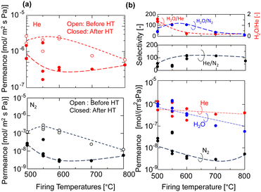 | ||
| Fig. 7 (a) Permeance of He and N2 of the AHPCS-derived membrane before and after HT (400 °C) and (b) He, N2 and H2O permeance and selectivities after HT. | ||
Characterization of hydrothermally treated AHPCS-derived materials
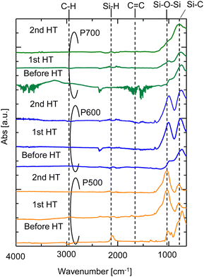
The FTIR spectra of the AHPCS powders (P500, P600, and P700) before and after the 1st HT and 2nd HT are shown in Fig. 8. The characteristic peaks of Si–H (2140 and 940 cm−1), C–H (2950–2873 cm−1), C![[double bond, length as m-dash]](https://www.rsc.org/images/entities/char_e001.gif) C (1630 cm−1), Si–C (747 cm−1), and Si–O–Si (1150 to 700 cm−1) bonds were observed for P500.16,26–28 The siloxane bond peaks slightly increased at 2 HT for P700, indicating a slight change in the surface structure of P700. This change also reportedly occurred under water vapor at 600 °C, although conversion to silica was low, around 1%.29 The change aligns with a minor decrease in N2 permeance in the membrane fired at 700 °C. However, for P500 and P600 after the 1st HT, the formation of siloxane bond peaks (
C (1630 cm−1), Si–C (747 cm−1), and Si–O–Si (1150 to 700 cm−1) bonds were observed for P500.16,26–28 The siloxane bond peaks slightly increased at 2 HT for P700, indicating a slight change in the surface structure of P700. This change also reportedly occurred under water vapor at 600 °C, although conversion to silica was low, around 1%.29 The change aligns with a minor decrease in N2 permeance in the membrane fired at 700 °C. However, for P500 and P600 after the 1st HT, the formation of siloxane bond peaks (![[triple bond, length as m-dash]](https://www.rsc.org/images/entities/char_e002.gif) Si–O–Si
Si–O–Si![[triple bond, length as m-dash]](https://www.rsc.org/images/entities/char_e002.gif) ) increased significantly owing to a change in the surface structure of the AHPCS powders, indicating that the oxidation reaction occurred during the hydrothermal treatment process. It is evident that
) increased significantly owing to a change in the surface structure of the AHPCS powders, indicating that the oxidation reaction occurred during the hydrothermal treatment process. It is evident that ![[triple bond, length as m-dash]](https://www.rsc.org/images/entities/char_e002.gif) Si–O–Si
Si–O–Si![[triple bond, length as m-dash]](https://www.rsc.org/images/entities/char_e002.gif) bonds (1150–700 cm−1) increased after hydrothermal treatment. Furthermore, the comparison between the 1st and 2nd HT indicates that almost no structural changes occurred after the 1st HT, again indicating the resistance of the AHPCS-membrane towards water vapor. This result is consistent with the findings in experiments of the polytitanocarbosilane-SiC derived membrane under hydrothermal conditions.19
bonds (1150–700 cm−1) increased after hydrothermal treatment. Furthermore, the comparison between the 1st and 2nd HT indicates that almost no structural changes occurred after the 1st HT, again indicating the resistance of the AHPCS-membrane towards water vapor. This result is consistent with the findings in experiments of the polytitanocarbosilane-SiC derived membrane under hydrothermal conditions.19
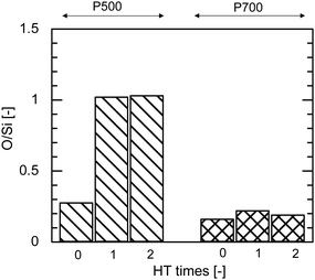
Fig. 9 shows the EDS analysis of the elemental composition ratio of O/Si before and after HT at 500 °C for AHPCS powders fired at 500 °C and 700 °C. The O/Si ratio of P500 significantly increased after the 1st hydrothermal treatment owing to the oxidation of SiC by steam as shown in Fig. 9, and was approximately constant after 2 HT, indicating the hydrothermal stability of the AHPCS-derived materials. In contrast, the O/Si ratio of P700 showed no significant changes even after the 2nd HT. The higher the firing temperature, the more stable the O/Si ratio.
The presence of –Si–C– bondings within the AHPCS membrane structure can significantly influence the membrane stability when exposed to vapor conditions. Si–O–Si bonds were generated by oxidation by steam under HT, but the C-rich structure of AHPCS enhanced the membrane stability under HT. When Si–O–Si bonds are prevalent in the AHPCS membrane structure, they contribute to its inherent properties. Si–O–Si bonds are susceptible to hydrolysis, which is a reaction with water molecules that can weaken the structural integrity of the membrane. Additionally, the presence of oxygen in the vapor environment can lead to the oxidation of SiC bonds, potentially causing structural degradation and weakening. Considering these factors, the presence of SiC-rich Si–O–Si bonds in the AHPCS membrane structure plays a pivotal role in determining its stability under vapor conditions.
Long-term hydrothermal stability and permeation properties of water vapor
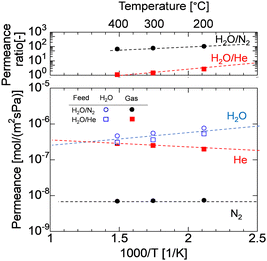
Long-term hydrothermal stability of the AHPCS membrane was evaluated in H2O/N2 (50/50) systems as long as 50 h. Fig. 10 shows the time course of N2 and H2O permeance of the M550-2 membrane under a steam partial pressure of 125 kPa-a at 400 °C, and the permeance was measured periodically during the hydrothermal treatment. The gas permeances of N2 and H2O were stable for 50 h after they decreased during the first 12 h from 1.7 × 10⁻⁷ to 5.8 × 10⁻⁹ mol m−2 s−1 Pa−1 for N2 permeance and 1.9 × 10⁻⁶ to 6.8 × 10⁻⁷ mol m−2 s−1 Pa−1 for H2O permeance. This indicates that the AHPCS membrane was resistant to water vapor for a long time (>24 h). Furthermore, the permeance ratio of H2O/N2 was also stable at ∼100 at 400 °C for over 24 h, which indicates that the water vapor was 100 times more permeable than N2. It is well-accepted that surface diffusion contributes to water vapor permeation through the pores. Transport through this type of membrane is complex, since it includes both diffusion in the gas phase and diffusion of the adsorbed phase on the surface of the pores (surface diffusion).24,30 Therefore, the temperature dependence of permeance of He, N2 and H2O was evaluated in binary mixtures of H2O/N2 and H2O/He at 200–400 °C.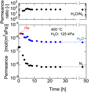 | ||
| Fig. 10 N2 and H2O permeance at 400 °C for long term hydrothermal treatment (50 h) in the H2O/N2 system of M550-2 membranes. | ||
Fig. 11 shows the Arrhenius plot of the permeances of M550-2. When the temperature increases, the He permeance increases owing to activated diffusion, where molecules permeating through the micropores were exposed to a repulsive force on the pore wall, and the molecules that had sufficient kinetic energy to surpass the repulsion force could permeate the pores. Meanwhile, the H2O permeance was decreased owing to the surface diffusion property, where adsorbed water on the surface of the pores diffused along the gradient of adsorbed H2O. In H2O/N2 binary mixtures, when the temperatures decreased, the H2O permeance increased while the N2 permeance was approximately constant, resulting in the H2O/N2 permeance ratio increasing approximately from 70 at 400 °C to 120 at 200 °C. Interestingly, the H2O permeance in H2O/N2 and H2O/He was approximately the same, indicating that the mixed gases had no effect. Similar trends are observed for M600 and M700 (Fig. S6, ESI†). Since the AHPCS membranes have a stable structure and are resistant to water vapor for a long time, they are promising for dehydration or steam recovery processes at high temperatures.
Comparison of the separation ability between AHPCS-derived membranes and other membranes
A comparison of the AHPCS-derived membranes with previously reported membranes, including PCS-derived SiC,15 organosilica,7,8,31,32 metal-doped SiO2,33 and zeolites,34–41 is summarized in Fig. 12. SiC membranes, including the PCS and AHPCS-derived membranes, are shown in red, organosilica membranes in blue, silica membranes in black, and Nafion membranes in green. Fig. 12(a) and (b) show H2O/N2 and H2O/He or H2O/H2 permeance ratios, respectively, of the binary gas mixture separations as a function of measurement temperature (150–500 °C) for the various types of membranes. It can be inferred that organosilica membranes were evaluated at a temperature of 100–200 °C, while silica and SiC membranes were evaluated at 300–500 °C. Fig. 12(a) also shows that the permeance ratios of H2O/N2 of the SiC-based membranes are comparable to or slightly lower than those of the organosilica membranes, indicating that water vapor can be selectively recovered under high-temperature steam. On the other hand, the H2O/H2 permeance ratios of organosilica are larger than 1, while H2O/H2 of silica (or H2O/He) and SiC membranes are less than 1 due to molecular sieving properties (Fig. 12(b)). Fig. 12(c) shows H2/N2versus H2O/H2 ratios for the organosilica, SiO2, and SiC membranes. H2/N2 as a non-adsorptive gas can be an indication of the membrane pore size; the larger the H2/N2, the smaller the pore size. SiO2 shows an H2/N2 permeance ratio greater than or equal to 100, but H2O/H2 is less than 1.0, which indicates that silica membranes are H2-selective due to the small pores. In contrast, the AHPCS and organosilica membranes have nearly similar levels of H2/N2 of 10–20, which indicates that both types of membranes have similar pore sizes. However, organosilica membranes showed a higher level of H2O/H2 at ∼10 (100–200 °C) than that of SiC-based membranes at <1 (300–500 °C). The surface of the AHPCS membrane is hydrophilic owing to siloxane bonds and silanol groups. On the other hand, the organosilica membrane is moderately hydrophobic due to the existence of organic bridging units (![[triple bond, length as m-dash]](https://www.rsc.org/images/entities/char_e002.gif) Si–CH2–CH2–Si
Si–CH2–CH2–Si![[triple bond, length as m-dash]](https://www.rsc.org/images/entities/char_e002.gif) ), which may have induced higher diffusivity, and therefore, low temperature operation (100–200 °C), which was favourable for water adsorption, may have resulted in higher water permeance than the AHPCS membrane. However, organosilica membranes cannot be used at high temperatures because of the decomposition of their organic components. The permeance and separation performance of the AHPCS-derived membranes were comparable to those of the other membranes. Importantly, steam can be separated and recovered in the binary gas with N2 under high-temperature steam.
), which may have induced higher diffusivity, and therefore, low temperature operation (100–200 °C), which was favourable for water adsorption, may have resulted in higher water permeance than the AHPCS membrane. However, organosilica membranes cannot be used at high temperatures because of the decomposition of their organic components. The permeance and separation performance of the AHPCS-derived membranes were comparable to those of the other membranes. Importantly, steam can be separated and recovered in the binary gas with N2 under high-temperature steam.
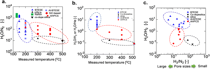 | ||
| Fig. 12 (a) Comparison of the separation factor of H2O/N2, (b) H2O/H2 or H2O/He, and (c) H2O/H2 as a function of H2/N2 between AHPCS-derived membranes and other types of membranes as a function of temperature. All data in Fig. 12 are tabulated in Table S3, ESI.† | ||
Conclusions
AHPCS membranes were prepared by firing at 300–800 °C and permeation properties and hydrothermal stability were evaluated. AHPCS membranes of high permeance and permselectivity were manufactured by firing at temperatures of 300–700 °C under a N2 atmosphere. By firing at 300–600 °C, AHPCS-derived SiC membranes formed loose networks, while firing at the temperature of 700–800 °C formed dense networks. Furthermore, the higher the firing temperature, the richer the SiC structures and the greater the steam resistance.In the evaluation of the hydrothermal stability of the AHPCS membrane, the gas permeance decreased over time under water vapor at 400 °C and a H2O partial pressure of 125 kPa, and reached stability. H2O/N2 permeance ratios of approximately 100 under 400 °C and stable water vapor permeance for extended time periods (>24 hours) indicate resistance to water vapor. H2O/N2 increased at lower temperatures since N2 permeated almost like Knudsen, while the water vapor permeated by surface diffusion. The H2O permeances in H2O/N2 and H2O/He were approximately the same, indicating no effect of the mixed gaseous types. Steam can be recovered in the binary gas with N2 under high-temperature conditions. The AHPCS membranes have been confirmed to have a stable structure and be resistance against water vapor for a long time, indicating that AHPCS-membranes are promising for dehydration or steam recovery processes at high temperatures.
Author contributions
T. T. conceptualized and supervised this work. G. S., and D. T. prepared the samples. G. S., D. T., and K. T. T. H. conducted the experiments. T. T., M. K., H. N., N. M., and G. S., wrote the manuscript with the help from all other authors. All authors contributed to the discussion of the results.Conflicts of interest
There are no conflicts to declare.Acknowledgements
Gusni Sushanti gratefully acknowledges financial support from the Next-Generation Fellowship program for developing and supporting the Next-Generation of innovative researchers at Hiroshima University. This work was supported by JSPS KAKENHI Grants Number JP22H04551, JP18H03855, JP22K18922, and JP19K22085.Notes and references
- Q. Wang, R. Zhou and T. Tsuru, Membranes (Basel), 2022, 12, 1225 CrossRef PubMed.
- C. Z. Liang, T.-S. Chung and J.-Y. Lai, Prog. Polym. Sci., 2019, 97, 101141 CrossRef CAS.
- R. Sidhikku Kandath Valappil, N. Ghasem and M. Al-Marzouqi, J. Ind. Eng. Chem., 2021, 98, 103–129 CrossRef CAS.
- T. Tsuru, in 60 Years of the Loeb-Sourirajan Membrane, ed. H. H. Tseng, W. J. Lau, M. A. Al-ghouti, L. An, Elsevier, Amsterdam, 2022, ch. 11, pp. 305–325 Search PubMed.
- T. Tsuru, J. Chem. Eng. Jpn., 2018, 51, 713–725 CrossRef CAS.
- T. Tsuru, R. Igi, M. Kanezashi, T. Yoshioka, S. Fujisaki and Y. Iwamoto, AIChE J., 2011, 57, 618–629 CrossRef CAS.
- N. Moriyama, H. Nagasawa, M. Kanezashi and T. Tsuru, Sep. Purif. Technol., 2021, 275, DOI:10.1016/j.seppur.2021.119191.
- N. Moriyama, H. Nagasawa, M. Kanezashi and T. Tsuru, J. Membr. Sci., 2019, 589, DOI:10.1016/j.memsci.2019.117254.
- X. Yu, Q. Wang, H. Nagasawa, M. Kanezashi and T. Tsuru, RSC Adv., 2020, 68, 10.1039/d0ra06919a.
- B. Elyassi, M. Sahimi and T. T. Tsotsis, J. Membr. Sci., 2007, 288, 290–297 CrossRef CAS.
- F. Chen, R. Mourhatch, T. T. Tsotsis and M. Sahimi, Chem. Eng. Sci., 2008, 63, 1460–1470 CrossRef CAS.
- R. J. Ciora, B. Fayyaz, P. K. T. Liu, V. Suwanmethanond, R. Mallada, M. Sahimi and T. T. Tsotsis, Chem. Eng. Sci., 2004, 59, 4957–4965 CrossRef CAS.
- Z. Li, K. Kusakabe and S. Morooka, J. Membr. Sci., 1996, 118, 159–168 CrossRef CAS.
- H. Suda, H. Yamauchi, Y. Uchimaru, I. Fujiwara and K. Haraya, Desalination, 2006, 193, 252–255 CrossRef CAS.
- M. Kubo, K. Okibayashi, M. Kojima, R. Mano, Y. Daiko, S. Honda, S. Bernard and Y. Iwamoto, Sep. Purif. Technol., 2021, 258, DOI:10.1016/j.seppur.2020.117998.
- Q. Wang, L. Yu, H. Nagasawa, M. Kanezashi and T. Tsuru, Sep. Purif. Technol., 2020, 248, DOI:10.1016/j.seppur.2020.117067.
- L. L. Le and D. S. Tsai, Ind. Eng. Chem. Res., 2001, 40, 612–616 CrossRef.
- C. L. Chen and D. S. Tsai, J. Membr. Sci., 2004, 237, DOI:10.1016/j.memsci.2004.03.010.
- Q. Wang, L. Yu, H. Nagasawa, M. Kanezashi and T. Tsuru, J. Am. Ceram. Soc., 2020, 103, 4473–4488 CrossRef CAS.
- Q. Wang, M. Yokoji, H. Nagasawa, L. Yu, M. Kanezashi and T. Tsuru, J. Membr. Sci., 2020, 612, DOI:10.1016/j.memsci.2020.118392.
- X. Yu, H. Nagasawa, M. Kanezashi and T. Tsuru, J. Mater. Chem. A, 2018, 6, 23378–23387 RSC.
- L. Yu, M. Kanezashi, H. Nagasawa, M. Guo, N. Moriyama, K. Ito and T. Tsuru, ACS Appl. Mater. Interfaces, 2019, 11, 7164–7173 CrossRef CAS PubMed.
- N. Moriyama, K. Haraya, H. Nagasawa, M. Kanezashi and T. Tsuru, AIChE J., 2020, 66, DOI:10.1002/aic.16250.
- R. W. Baker, Membrane Technology and Applications, John Wiley & Sons, Ltd, 2012, pp. 325–378 Search PubMed.
- G. Li, H. R. Lee, H. Nagasawa, M. Kanezashi, T. Yoshioka and T. Tsuru, AIChE J., 2015, 61, 2268–2279 CrossRef CAS.
- S. Kaur, R. Riedel and E. Ionescu, J. Eur. Ceram. Soc., 2014, 34, 3571–3578 CrossRef CAS.
- S. Kaur, S. Fischer, J. Falta, K. Rezwan and M. Wilhelm, J. Am. Ceram. Soc., 2019, 102, 7187–7197 CrossRef CAS.
- Z. Yu, L. Yang, H. Min, P. Zhang, C. Zhou and R. Riedel, J. Mater. Chem. C, 2014, 6, 1057–1067 RSC.
- M. Fukushima, Y. Zhou, Y. Yoshizawa and K. Hirao, J. Eur. Ceram. Soc., 2008, 28, 1043–1048 CrossRef CAS.
- N. Moriyama, H. Nagasawa, M. Kanezashi and T. Tsuru, Chem. Eng. Sci., 2022, 263, DOI:10.1016/j.ces.2022.118083.
- N. Moriyama, M. Ike, H. Nagasawa, M. Kanezashi and T. Tsuru, RSC Adv., 2022, 12, 5834–5846 RSC.
- N. Moriyama, H. Nagasawa, M. Kanezashi and T. Tsuru, J. Membr. Sci., 2021, 620, DOI:10.1016/j.memsci.2020.118895.
- M. Kanezashi, T. Sasaki, H. Tawarayama, T. Yoshioka and T. Tsuru, J. Am. Ceram. Soc., 2013, 96, 2950–2957 CrossRef CAS.
- H. Azher, C. A. Scholes, G. W. Stevens and S. E. Kentish, J. Membr. Sci., 2014, 459, 104–113 CrossRef CAS.
- T. F. Mastropietro, A. Brunetti, P. F. Zito, T. Poerio, H. Richter, M. Weyd, S. Wöhner, E. Drioli and G. Barbieri, Sep. Purif. Technol., 2015, 156, 321–327 CrossRef CAS.
- K. Aoki, K. Kusakabe and S. Morooka, Ind. Eng. Chem. Res., 2000, 39, 2245–2251 CrossRef CAS.
- S. M. Lee, N. Xu, J. R. Grace, A. Li, C. J. Lim, S. S. Kim, F. Fotovat, A. Schaadt and R. J. White, J. Eur. Ceram. Soc., 2018, 38, 211–219 CrossRef.
- J. Gorbe, J. Lasobras, E. Francés, J. Herguido, M. Menéndez, I. Kumakiri and H. Kita, Sep. Purif. Technol., 2018, 200, 164–168 CrossRef CAS.
- P. G. Ingole, M. I. Baig, W. Choi, X. An, W. K. Choi, J. D. Jeon and H. K. Lee, Chem. Eng. Res. Des., 2017, 127, 45–51 CrossRef CAS.
- R. Raso, M. Tovar, J. Lasobras, J. Herguido, I. Kumakiri, S. Araki and M. Menéndez, Catal. Today, 2021, 364, 270–275 CrossRef CAS.
- H. J. Lee, Y. M. Shirke, J. Kim, H. J. Yu, C. H. Yoo, S. Back, J. D. Jeon and J. S. Lee, J. Membr. Sci., 2023, 665, DOI:10.1016/j.memsci.2022.121096.
Footnote |
| † Electronic supplementary information (ESI) available. See DOI: https://doi.org/10.1039/d3ma01005h |
| This journal is © The Royal Society of Chemistry 2024 |

