 Open Access Article
Composite lithium conducting solid electrolytes based on zwitterionic plastic crystals and polymer nanoparticles†
Faezeh
Makhlooghiazad
 *a,
Luca
Porcarelli
ab,
David
Mecerreyes
 b,
Maria
Forsyth
a,
Luke A.
O’Dell
 a and
Jennifer M.
Pringle
 *a
*a
aDeakin University, Institute for Frontier Materials, Burwood, Victoria 3125, Australia. E-mail: f.makhlooghiazad@deakin.edu.au; j.pringle@deakin.edu.au
bPOLYMAT University of the Basque Country UPV/EHU, Joxe Mari Korta Center 20018, Donostia–San Sebastian, Spain
First published on 7th February 2024
Abstract
Organic ionic plastic crystals (OIPCs) are promising materials for the development of solid-state electrolytes for next-generation energy storage devices with improved safety. Zwitterionic plastic crystals, in which the cationic and anionic groups are covalently bound, are a promising alternative to traditional OIPC-based electrolytes as they offer a route to higher target ion transport by reducing the number of competing ions. Incorporating polymeric nanoparticles (NPs) into OIPC matrixes can create solid-state electrolytes with increased mechanical stability and enhanced ionic conductivity, but this has never been investigated for the plastic zwitterion-based electrolytes. In this work, we designed self-standing, conductive zwitterionic-based composite materials by combining lithium functionalised polymer nanoparticles with a zwitterion. The further addition of either lithium salt or solvent can be used to optimise conductivity and/or transference number of the solid electrolyte. The novel composite electrolytes prepared via this strategy offer a promising new pathway for the development of conductive and safe electrolytes for all solid-state lithium metal batteries.
Introduction
Safety is a critical concern for commercial lithium batteries, since many factors such as dendrite penetration, side reactions and overcharging can cause exothermic reactions that lead to ignition of the carbonate-based liquid electrolyte.1,2 Solid-state electrolytes are considered an effective approach to increase the safety of next generation batteries, by replacing standard carbonate liquid electrolytes with solid electrolytes that have good ionic conductivity, mechanical integrity, thermal and electrochemical stability.3–7Organic ionic plastic crystals (OIPCs) are a class of solid-state electrolytes that are non-flammable and have shown promising performance in Na and Li devices upon addition of sodium or lithium salts.8–13 These materials possess rotational/orientational motions of ions that give them plasticity, while they also have long-range ordered crystalline structures. Having plasticity improves their interfacial contact with electrode materials and hence supports good battery performance.14,15 However, as OIPCs are composed of cations and anions, all ions may move through the electrolyte and compete with the target Li or Na caions.
We recently reported a new type of plastic crystal material composed of zwitterions (ZIs) in which the cationic and anionic moiety are covalently attached to each other to make a molecule with zero overall charge. As for OIPCs they are structurally disordered, but their net zero charge is designed to suppress migration in an electric field and thus allow them to be used as a matrix electrolyte without competing with the transport of target ions.16
Zwitterions, mainly with the sulfonate –SO3− functional group and without indicators of molecular disorder, have previously been investigated as electrolyte additives to improve the ionic conductivity, decrease interfacial resistance between electrode and electrolyte, and improve electrochemical performance within carbonate electrolytes,17,18 and ionic liquids.19 They have also been used to improve Li ion dissociation, target ion transport number and stability of polymer and gel polymer electrolytes in Li metal batteries.20–23 The zwitterionic plastic crystals that we reported recently have a trifluoroborate (–BF3−) functional group, which can be covalently bound to cationic groups such as pyrrolidinium or morpholinium.16 We demonstrated that mixtures of the pyrrolidinium ZI ([C1mpyrBF3], Fig. 1) with different concentration of LiFSI can be used to form solid (10 mol% LiFSI) or liquid (50 mol% LiFSI) electrolytes, and that these supported stable cycling of Li metal batteries.16 We have also studied the impact of different lithium salts (LiFSI vs. LiBF4) in combination with this ZI.24 However, the mixture of ZI with Li salt results in either soft solid, quasi-solid or liquid electrolytes. The development of mechanically stronger, self-standing membranes is important for the application of the ZI-based materials as solid state electrolytes in Li metal batteries as they can help to mitigate leakage and dendrite growth.
One effective strategy for increasing mechanical strength and achieve self-standing electrolyte membranes is to combine electrolytes (such as organic carbonates or ionic liquids) with inorganic nanoparticles such as silica (SiO2),25–27 or titanium oxides (TiO2).28,29 Another strategy is to use single ion conductors, in which the nanoparticle surface is functionalized with immobilized anions or polyanions and the lithium ions are present as the mobile counter-ions. This allows the creation of a self-standing membrane as well as adding a source of Li ions, which can lead to increased ionic conductivity.11 Recently some of us,30,31 have reported the synthesis of methacrylic polymer nanoparticles, based on a common co-monomer methyl methacrylate and the anionic co-monomer lithium 1–(3 (methacryloyloxy)propylsulfonyl)–1–(trifluoromethylsulfonyl)imide (LiMTFSI). The polymeric nanoparticles (100 nm) based on crosslinked poly(MMA-co-LiMTFSI) were synthesized by a emulsion polymerization process that can be readily scaled-up. These nanoparticles are well suited to design single-lithium ion conducting gel or composite electrolyte by mixing the nanoparticles (as the only source of Li) with propylene carbonate (PC) or a polymer matrix to produce an electrolyte with Li transference number close to unity and ionic conductivity up to 10−4 S cm−1 at 70 °C.30
Here, we report the development of ZI-based composite electrolytes utilising the lithium-sulfonamide-functionalised methacrylic nanoparticles (NPs): by adopting two strategies. In the first strategy, a small amount of propylene carbonate (PC) was used as a plasticizer for the NP/ZI composite, and to promote ion dissociation from the polymer backbone and hence improve the ionic conductivity. The second strategy was to add some lithium salt to the ZI/NP composite, to increase the Li ion concentration, and investigating the effect of different volume fractions of nanoparticles. Comparing these two strategies allows investigation into achieving the optimum benefit of thermal properties, conductivity, mechanical integrity and non-volatility and has yielded novel zwitterion-based composite electrolyte materials with advantageous properties for electrochemical device applications.
Experimental
Synthesis of zwitterion and polymeric nanoparticles
ZI/NP or ZI-LiFSI/NP composites were prepared by solution casting method. Selected volume fractions of ZI and NPs were dispersed in anhydrous Acetonitrile (99.8%, Sigma-Aldrich). The mixture was sonicated for 30 minutes to uniformly distribute the NPs and ZI in the solvent and stirred to form a uniform suspension. The suspension was cast on a Petri dish, and the acetonitrile was evaporated at room temperature under argon flow in a fume hood. The sample was then collected from the Petri dish and ground in an agate mortar to ensure uniform distribution of the NPs and ZI. Finally, the sample was dried under vacuum at 50 °C on a Schlenk line for 24 hours to remove all traces of the solvent. The samples were then transferred into an argon- filled glove box for storage prior to characterization. To prepare ZI/NP/propylene carbonate (PC) composites, the prepared ZI/NP materials were mixed with anhydrous PC (99.7%, Sigma-Aldrich) in pestle and mortar inside the glove box.
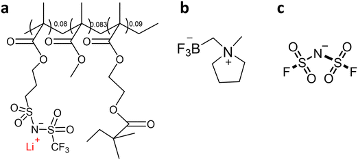
ZI/LiFSI mixtures were prepared in an argon-atmosphere glove box using anhydrous acetonitrile (99.8%, Sigma-Aldrich) to create a homogenous solution. The acetonitrile was subsequently removed under high vacuum at 60 °C for 2 days. The resulting ZI/LiFSI mixtures were used to produce composite electrolytes with NP s following the previously described procedures. Fig. 1 shows the chemical structures of the ZI, NPs and LiFSI.
Solid-state nuclear magnetic resonance (NMR) spectroscopy
Static solid-state NMR spectroscopy was performed on a Bruker Avance III 500WB spectrometer equipped with a 5 mm H/F-X double resonance probe. Samples were packed into standard 5 mm zirconia rotors inside an argon glove box. The Topspin software was used to record and analyse the data. To calculate full width at half maximum (FWHM) some of the spectra were deconvoluted based on Gaussian/Lorentzian functions. Additionally, 19F MAS and 2D 19F-7Li HETCOR (heteronuclear correlation) spectra were obtained on the same spectrometer with a 2.5 mm HXY MAS NMR probe and a spinning rate of 20 kHz. For the HETCOR spectrum, the cross polarisation contact time was set to 2 ms.Results and discussion
Composites of zwitterion and nanoparticles
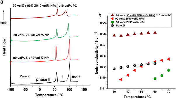
In the first strategy, the ZI was mixed with the methacrylic polymeric nanoparticles (NPs) in different volume ratio of 10 to 90 vol% NP loadings. DSC was used to study the phase behaviour of the composite electrolytes (Fig. 2 and Fig. S1a and b, ESI†). The enthalpy changes were normalized to the weight of ZI and are shown in Table S1 (ESI†). Mixing ZI with 10 and 50 vol% NPs did not substantially alter the phase II–I transition and melting temperatures, and these were well defined in the first run. However, in the second heating scan of the 50 vol% NP composite (Fig. S1, ESI†) the solid–solid phase transition (at 56 °C) overlapped with melting transition (97 °C) of the zwitterion. This change in phase behaviour of the composite in the second heating scan may be a result of increased interactions of the NPs and ZI caused by swelling of the NPs with the molten ZI after the first run.The ionic conductivities of the composite electrolytes, presented in Fig. 2b, all increase with temperature. The ionic conductivity of the electrolyte containing 10 vol% NPs surpasses that of the neat ZI above the solid–solid phase transition at 54 °C. This is consistent with a more disordered structure in the composite, due to increased dynamics of the zwitterion after this transition facilitating motion of the Li ions. Conversely, the ionic conductivity for the 50 vol% NPs in ZI is significantly lower than the neat ZI. This is attributed to the increased mechanical rigidity and potentially poorer contact between the electrolyte and electrodes. Notably, the activation energy is higher in the NP-containing samples, which may be due to the influence of tortuosity on the ion transport in the composites.
Based on the higher ionic conductivity of the composite containing 10 vol% NPs compared to the one composed of 50 vol% NPs, the former composite was selected for further study and was directly mixed with a low molecular weight, high dielectric constant plasticizer to increase the plasticity of the composite. In this work 10 vol% propylene carbonate (PC) (as a polar additive) was used, with the aim of dissociating Li ions and providing a more mobile medium for the ions and hence increasing the ionic conductivity.32,33 The effect of the PC on the phase behaviour of the 10 vol% NPs/90 vol% ZI is shown in Fig. 2a. The enthalpy of the melting decreased from 56 to 30 J g−1 (normalised to ZI content), which is evidence of more disorder in the sample. The ionic conductivity of this electrolyte significantly increased from 10−9 S cm−1 without PC (10 vol% NPs/90 vol% ZI) to 10−6 S cm−1 with PC, at 50 °C, as shown in Fig. 2b.
By this strategy, the development of the ZI-based composite as a single ion conductor was successfully achieved as the ionic conductivity belongs only to the mobility of the Li ions. However, the incorporation of flammable carbonate electrolytes in Li batteries still leaves a safety concern, especially when using highly reactive Li–metal as the anode. Thus, an alternative composite was explored to improve the ionic conductivity while also addressing safety issues.
Composites of zwitterion + LiFSI and nanoparticles
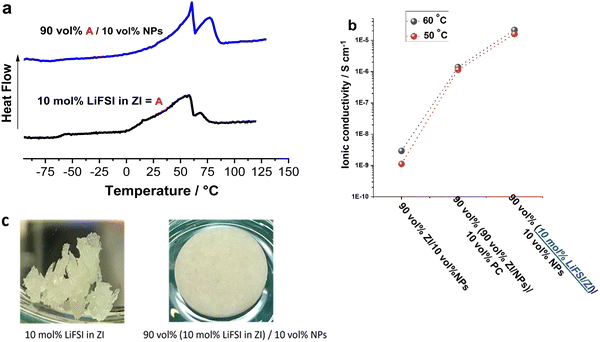
In the second strategy, 10 vol% NPs was added to a mixture of 10 mol% LiFSI in ZI instead of pure ZI, to combine the benefits of the mechanical properties of the NPs with the ionic conductivity of the LiFSI/ZI. As presented in Fig. 3a, adding 10 vol% NPs does not substantially change the phase behaviour of the previously reported 10 mol% LiFSI in ZI mixture.16 The most significant change is the sharpening of the first peak in the 10 mol% LiFSI in ZI mixture, named as composition A in Fig. 4, upon the addition of NPs. The increased sharpness of the peak following NP addition may be a result of the interaction between ZI and NPs, which induces a more ordered structure. Consistent with this, all composite materials with NP additions exhibited higher enthalpy in the melting peak, indicating a higher rigidity of the composite materials. This increased rigidity could be a contributing factor to the observed sharper transitions. Furthermore, the addition of NPs, up to 20 vol%, facilitated the formation of a self-standing pellet from a quasi-solid material in the ZI/10 mol% LiFSI sample. Interestingly, the ionic conductivity of the composite with LiFSI (Fig. 3b) is higher than the PC-containing composite discussed above but without the disadvantage of using flammable solvent. In addition, this electrolyte contains FSI anions that can form a stable solid electrolyte interphase (SEI), which helps mitigate electrolyte decomposition and improve cell stability.34–36 It is also important to note that while the 10 mol% LiFSI in ZI sample has a quasi-solid nature (i.e. with a small amount of liquid phase present) and lacks mechanical strength (Fig. 3c), adding 10 vol% NPs enhances the mechanical strength and allows the material to be pressed into a self-standing pellet. The Li transference number of the NP in propylene carbonate has been reported to be 0.8. By using ZI/LiFSI as a non-volatile environment for the NPs,31 the Li transference number has been calculated to 0.6, which is significantly higher than the material without NPs (10 mol% LiFSI in ZI) reported to be 0.29 ± 0.05.16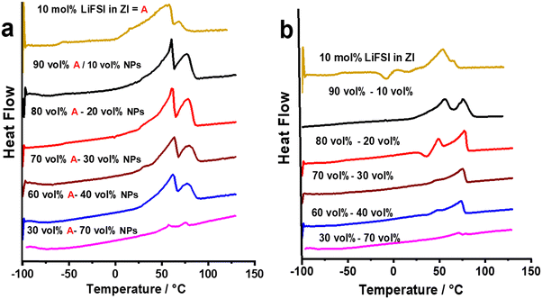 | ||
| Fig. 4 The DSC traces of (a) 10 mol% LiFSI in ZI (composition A) with different concentrations of nano particles, First heating scan. (b) second heating scan. | ||
Following the successful development of the above composite with 10 vol% NPs, we then explored the impact of adding more NPs into the 10 mol% LiFSI in ZI mixture as a route to further optimise the properties. Increasing the proportion of lithium-functionalised nanoparticles has the potential advantage of increasing the number of charge carriers (Li+) without compromising transference number, but there exists a trade-off with decreased conductivity as the polymer content and rigidity increases.16
The DSC heating traces for 10 mol% LiFSI in ZI mixed with 10, 20, 30, 40 and 70 vol% NPs are presented in Fig. 4a. There is no substantial change in the phase behaviour of the first heating scan upon increasing the NP concentrations. However, a notable change in phase behaviour is the broadening of the melting transition at 63 °C as NPs are added. This could be attributed to more heterogeneous compositions in the composite materials, and possibly lower thermal conductivity that could result in a temperature gradient across the sample. The phase behaviour of each composition is different in the second heating scan compared to the first one, as shown in Fig. 4b. In both runs (Fig. 4) a solid–solid phase transition followed by a rather broad melting peak is evident. However, in the second heating of the neat ZI, 10 mol% LiFSI in ZI mixture, and the composites with NPs there is a cold crystallisation. This crystallisation transition indicates that these samples do not readily freeze upon cooling. This suggests that these samples are prone to supercooling and exhibit slow kinetics in reaching their thermodynamically stable state, resulting in the presence of a metastable phase. Similar behaviour has been noted previously with different OIPC/Na salts,37 and composites of OIPC/Na salts/electrospun PVDF.38
In the second heating scan, the melting peak shifts to a lower temperature (from 65 °C in the first heating scan for the 10 vol% NPs composites to 60 °C in the second scan) and the enthalpy of the solid–solid phase transitions decrease. One possible reason for this change may be after melting of the ZI/LiFSI mixture, this mixture interacts with the NPs and upon cooling forms a new, lower melting composite phase composed of Li salt, ZI and NPs.
The ionic conductivities of the composite electrolytes with different NP loadings were measured in the temperature range of 30 to 55 °C, shown in Fig. 5. The conductivity of the composites exhibits slight increase with increasing NP content, with conductivity values being similar for 10% and 20% vol NPs. However, beyond 20% vol NPs, the conductivity starts to decrease. At 45 °C, the conductivity of composites containing 10% and 20% vol NPs is 1.0 × 10⁻⁵ and 1.3 × 10⁻⁵ S cm−1, respectively, compared to 7.6 × 10⁻⁶ S cm−1 in the sample without NPs. The sample with the highest NP loading of 50% vol exhibits the lowest ionic conductivity, measuring 9.6 × 10⁻⁷ S cm−1 at 50 °C. The decrease in ionic conductivity with higher NP fraction can likely be attributed to increased composite rigidity.
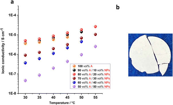 | ||
| Fig. 5 (a) Ionic conductivity of 10 mol% LiFSI in ZI (A) with different concentrations of nano particles. (b) Photograph of the 60 vol% A/40 vol% NPs. | ||
Since the ionic conductivity of 90 vol% (10 mol% LiFSI in ZI)/10 vol% NP composite is very close to the one in 20 vol% NPs but with lesser NP content, this sample was selected to further investigate the ionic environment and dynamics in the composites by NMR over a range of temperatures.
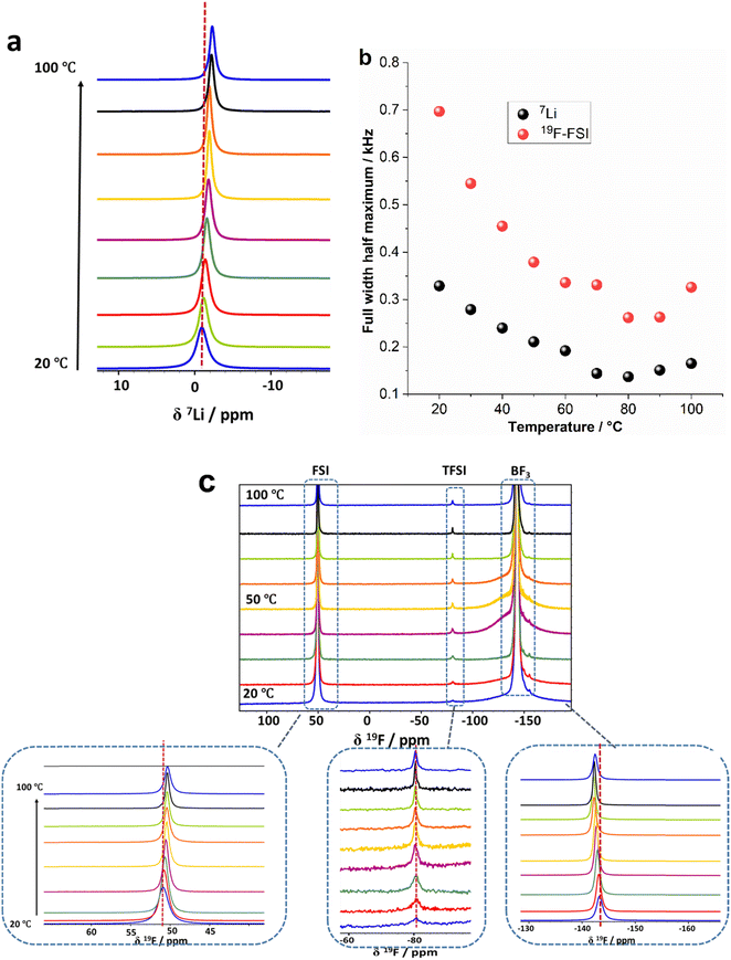
Analysing the 7Li and 19F chemical shifts can provide insight into changes in the local environments of the Li+ and anions respectively, in the presence of the NPs, and how this is altered with temperature.39 In addition to providing valuable insights into the material, it is worth noting that an electrolyte within a lithium metal cell will be exposed to a range of temperatures during operation and thus the effect of temperature on the material properties is also relevant to their application. Fig. 6a shows the static 7Li NMR spectra of the 90 vol% (10 mol% LiFSI in ZI)/10 vol% NPs during a first heating from 20 to 100 °C. It should be noted that the fraction of Li from LiFSI is 91% compared to 9% from NPs. Fig. 6a and Fig. S2 (ESI†) show a shift of the 7Li peak position to more negative chemical shifts occurs with increasing temperature (−0.94 ppm at 20 °C to −2.3 ppm at 100 °C). This shift indicates that the average environment around the Li ions is changing with temperature. The full width half maximum (FWHM) of the 7Li signals shown in Fig. 6b is narrower compared to pure LiFSI and pure NPs,16 for the whole range of temperatures, indicating higher Li ion mobility within the electrolyte. The FWHM of the 7Li signals (Fig. 6b) becomes slightly narrower as the temperature is increased (0.33 kHz at 20 °C to 0.13 kHz at 80 °C), indicating higher mobility of the Li ions at higher temperatures as would be expected. The gradual increase in linewidth in the composite is primarily attributed to the presence of LiFSI. As reported previously, the eutectic transition at 13 °C results in the formation of a liquid phase fraction at a temperature lower than the range we investigated (20 °C). This liquid phase introduces disorder to the materials, leading to a more gradual decrease in line width as the temperature increases.16,24
Fig. S3 (ESI†) compares the 7Li NMR spectra of the first and second heating scan of the 90 vol% (10 mol% LiFSI in ZI)/10 vol% NPs at 50 °C. The linewidths of the 7Li spectra remain unchanged during the first and second heating scans but a shift in the peak position in the second heating scan to a less negative chemical shift relative to the first heating scan was observed. This shift can likely be attributed to the melting of ZI during the first heating scan. The melting causes more intimate mixing of the zwitterions and the polymer NPs, leading to a change in the local coordination structure of the Li ions (e.g. increased interactions of the Li+ with the electronegative oxygen groups of the polymer), with greater shielding of the Li nucleus. This behaviour was also observed in the composite containing [C2mpyr][TFSI]/LiTFSI with this NPs.40 This is consistent with the phase behaviour results in Fig. 4a and Fig. S2 (ESI†) of different transition peaks in the second heating in comparison with the first heating scan that indicate increased interaction between the ZI and the NPs or swelling of the ZI after melting this component.
Fig. 6c shows static 19F NMR spectra at different temperatures from 20 to 100 °C. Three peaks at 50.9 ppm, −80.7 ppm and −143.0 ppm at 20 °C, assigned to FSI anion, TFSI anion and –BF3 groups respectively, were observed. The peak from the TFSI anions is much less intense because the TFSI is the counterion for the NPs and only 10 vol% NPs are present in the electrolyte. In the 19F NMR spectra (Fig. 6c) only one narrow peak was observed for the FSI anion across the whole temperature range studied. This is similar to the 7Li spectra, indicating isotropic rotational dynamics of the molecule which averages the dipolar interactions and thus decreases the linewidth. The 19F NMR signals from the –BF3 group (which is bound to the positive moiety of the zwitterion), however, show a broad component and a narrow component with a ratio of 1.2 to 1 at 20 °C. This was also observed in the 10 mol% LiFSI in ZI mixture without NPs,16 and indicates the presence of a component with higher dynamics of the zwitterion molecules (or at least the –BF3− part of the molecules) as well a less dynamic component.
The 19F solid-state MAS NMR spectrum obtained from a mixture containing 90 vol% (10 mol% LiFSI in ZI) and 10 vol% NPs is presented in Fig. 7a. This spectrum exhibits three well-defined isotropic signals: one originating from the fluorine of the FSI− anions at 50.9 ppm, another from the TFSI groups at −80.7 ppm, and a third from the –BF3− groups. Notably, the –BF3− signal displays two distinct peaks of ratio 2.3![[thin space (1/6-em)]](https://www.rsc.org/images/entities/char_2009.gif) :
:![[thin space (1/6-em)]](https://www.rsc.org/images/entities/char_2009.gif) 1 at −139 and −143 ppm, implying the existence of two unique structural environments for the –BF3− groups.
1 at −139 and −143 ppm, implying the existence of two unique structural environments for the –BF3− groups.
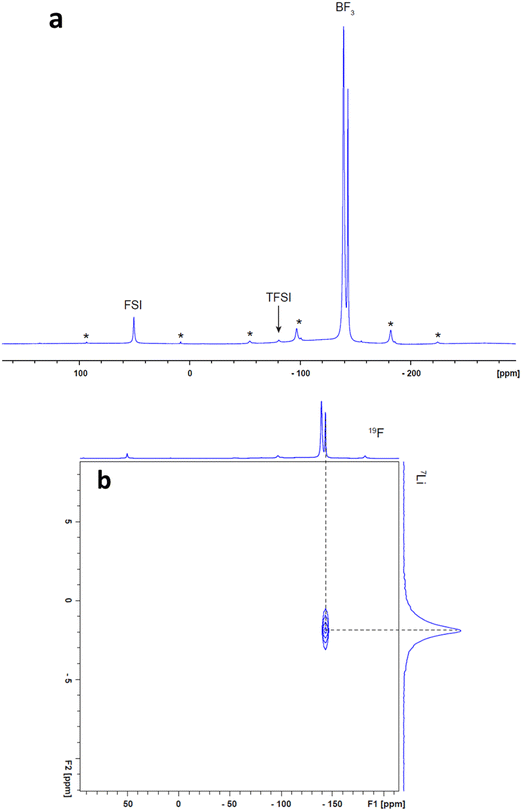 | ||
| Fig. 7 High-field solid-state MAS NMR spectra obtained from the 90 vol% A/10 vol% NPs (a) 19F spectrum, (b) 19F-7Li HETCOR spectrum. * indicates spinning side bands. | ||
The 2D 19F-7Li heteronuclear correlation (HETCOR) experiment have been conducted to reveal which fluorine and lithium group are bonded to each other. The results only show a lithium cross peak with the –BF3− anions, indicating that the –BF3− anions strongly interact with Li+ ions, as shown in Fig. 7b, presumably due to the more localised negative charge on these groups compared with the FSI and TFSI species. Interestingly, the cross peak in the HETCOR spectrum seems to line up with just one of the two –BF3 peaks (the smaller peak at more negative chemical shift). This implies that the second 19F peak at −139 ppm comes from ZI species that are not coordinated with Li+ ions; instead, it is presumably interacting with the positively charged component of the ZI. No cross peaks were observed between 7Li and the 19F signals of the FSI and TFSI groups. This observation suggests that the complexes formed between FSI− and TFSI− and Li+ ions may have short lifetimes within the timescale of the NMR experiment, making them challenging to detect (particularly when combined with the much less intense 19F signals from these groups) in contrast to the –BF3− complexes with Li+. To gain a deeper insight into the coordination dynamics involving FSI, TFSI, and Li ions, we intend to perform diffusion coefficient measurements using NMR and analyse T1/T2 relaxation times in the future work. These investigations are capable of capturing both rotational and translational dynamics, offering a comprehensive understanding of the dynamics, both quantitatively and qualitatively. Examining the temperature dependence of these parameters will enable us to gain valuable insights into the short lifetimes of the complexes formed between FSI− and TFSI anions and Li+ ions within the timeframe of the NMR experiment.
The interaction between –BF3− and Li+ ions appear to intensify with increasing temperature. This is evident in the 7Li and 19F NMR spectra in Fig. S2 (ESI†), where raising the temperature of the electrolyte from 20 to 100 °C causes a shift of the 7Li peak position to more negative chemical shifts and in contrast the 19F peak position of the –BF3− shift to less negative chemical shift values. These changes in the chemical shifts of –BF3− and Li ions suggest the presence of correlated interactions between them. The 19F peak positions of the FSI anions shift to less positive chemical shift values that indicates the surrounding environment of FSI anions also undergoes changes, possibly due to interactions with the positively charged portion of the ZI.
The linewidth of the pendant sulfonylimide groups on the polymer is broader than for the FSI anions, as a result of the lower mobility. There is also no change in chemical shift with increasing temperature, indicating that these chemically bonded anionic groups are less influenced by changes in the ionic environment within the composite upon heating.
Conclusion
Solid-state composite electrolytes based on zwitterions and Li sulphonamide functionalized methacrylic polymeric nanoparticles have been prepared and characterised towards their application in all-solid-state Li battery applications. Two approaches for optimising the physical and transport properties of the composites were explored. In the first approach, a composite of 10 vol% NPs/90% ZI mixed with 10 vol% propylene carbonate (PC) was used to make a single ion conducting gel polymer electrolyte. The composite electrolyte exhibited good ionic conductivity of 1.1 × 10⁻⁶ S cm−2 at 50 °C.In the second strategy, to avoid the use of flammable solvent, we used 10 mol% LiFSI in ZI instead of the pure ZI and mixed it with different volume ratios of NPs. Analysis by DSC revealed that adding NPs into the ZI/LiFSI mixture did not change the phase behaviour in the first heating scan, but it did alter the crystallisation kinetics after melting. Importantly, addition of 10 vol% NPs to the 90 vol% (10 mol% LiFSI in ZI) mixture improved the physical properties, transforming it from a soft quasi-solid-state material to one that could be pressed into free standing pellets.
Solid-state NMR analysis has provided valuable insights into the interionic interactions within the electrolyte membranes. It has revealed unique structural environments for –BF3− groups and has demonstrated the formation of strong interactions between –BF3− groups and Li+ ions. Consequently, this leads to observable chemical shifts in the peaks associated with Li ions and –BF3− as the temperature rises. Importantly, these interactions weakened the bonding between FSI− anions and Li+ ions.
The ionic conductivity of the composite electrolyte with 10 vol% LiFSI in the 10 vol% NPs/90% ZI (1.4 × 10⁻⁵ S cm−1) was higher than the composite obtained from the first strategy using PC (1.1 × 10⁻⁶ S cm−1) at 50 °C. In summary, composite electrolytes that address the competing challenges of Li ion conductivity, mechanical properties and safety are important for the development of lithium batteries. In this work, we presented promising new zwitterion-based composites formed using lithium sulfonamide functionalised polymer nanoparticles, and insights into the compositional optimisation and characterisation that can help address these challenges.
Author contributions
Faezeh Makhlooghiazad: conceptualization, experimental design, methodology, investigation, data analysis, writing original draft. Luca Porcarelli: lithium sulfonamide functionalised polymer nanoparticles synthesis. Luke A. O’Dell: NMR supervision and NMR data interpretation. Jennifer M. Pringle: conceptualization, supervising, scientific discussion and understanding of concept. David Mecerreyes: conceptualizing of the polymer synthesis, scientific discussion and understanding of concepts, Maria Forsyth: scientific discussion and understanding of concepts, Funding acquisition.Conflicts of interest
There are no conflicts to declare.Acknowledgements
The authors would like to acknowledge the Australian Research Council Centre of Excellence for Electromaterials Science (ACES) for funding through CE140100012 and the Australian Research Council Training Centre in Future Energy Storage Technologies for funding through IC180100049 (StorEnergy). L. P. has received funding from the European Union's Horizon2020 research and innovation programme under the MarieSkłodowska–Curie grant agreement no. 797295.References
- Z. Wu, Z. Xie, J. Wang, T. Yu, X. Du, Z. Wang, X. Hao, A. Abudula and G. Guan, Int. J. Hydrogen Energy, 2020, 45, 19601–19610 CrossRef CAS.
- N. Lu, X. Zhang, R. Na, W. Ma, C. Zhang, Y. Luo, Y. Mu, S. Zhang and G. Wang, J. Colloid Interface Sci., 2019, 534, 672–682 CrossRef CAS PubMed.
- Z. Zhang, Y. Shao, B. Lotsch, Y.-S. Hu, H. Li, J. Janek, L. F. Nazar, C.-W. Nan, J. Maier and M. Armand, Energy Environ. Sci., 2018, 11, 1945–1976 RSC.
- X. Wang, H. Zhu, G. W. Greene, Y. Zhou, M. Yoshizawa-Fujita, Y. Miyachi, M. Armand, M. Forsyth, J. M. Pringle and P. C. Howlett, Adv. Mater. Technol., 2017, 2, 1700046 CrossRef.
- Q. Zeng, Y. Lu, P. Chen, Z. Li, X. Wen, W. Wen, Y. Liu, S. Zhang, H. Zhao and H. Zhou, Journal of Energy Chemistry, 2021 Search PubMed.
- Q. Pang, A. Shyamsunder, B. Narayanan, C. Y. Kwok, L. A. Curtiss and L. F. Nazar, Nat. Energy, 2018, 3, 783–791 CrossRef CAS.
- Y. Zhou, X. Wang, H. Zhu, M. Yoshizawa-Fujita, Y. Miyachi, M. Armand, M. Forsyth, G. W. Greene, J. M. Pringle and P. C. Howlett, ChemSusChem, 2017, 10, 3135–3145 CrossRef CAS PubMed.
- M. Forsyth, T. Chimdi, A. Seeber, D. Gunzelmann and P. C. Howlett, J. Mater. Chem. A, 2014, 2, 3993–4003 RSC.
- F. Makhlooghiazad, J. Guazzagaloppa, L. A. O’Dell, R. Yunis, A. Basile, P. C. Howlett and M. Forsyth, Phys. Chem. Chem. Phys., 2018, 20, 4721–4731 RSC.
- F. Makhlooghiazad, D. Gunzelmann, M. Hilder, D. R. MacFarlane, M. Armand, P. C. Howlett and M. Forsyth, Adv. Energy Mater., 2017, 7, 1601272 CrossRef.
- S. Tian, B. Shao, Z. Wang, S. Li, X. Liu, Y. Zhao and L. Li, Chin. Chem. Lett., 2019, 30, 1289–1292 CrossRef CAS.
- K. Yang, Z. Liao, Z. Zhang, L. Yang and S.-I. Hirano, Mater. Lett., 2019, 236, 554–557 CrossRef CAS.
- Z.-B. Zhou and H. Matsumoto, Electrochem. Commun., 2007, 9, 1017–1022 CrossRef CAS.
- L. Jin, K. M. Nairn, C. M. Forsyth, A. J. Seeber, D. R. MacFarlane, P. C. Howlett, M. Forsyth and J. M. Pringle, J. Am. Chem. Soc., 2012, 134, 9688–9697 CrossRef CAS PubMed.
- K. Goossens, L. Rakers, B. Heinrich, G. Ahumada, T. Ichikawa, B. Donnio, T. J. Shin, C. W. Bielawski and F. Glorius, Chem. Mater., 2019, 31, 9593–9603 CrossRef CAS.
- F. Makhlooghiazad, L. A. O'Dell, L. Porcarelli, C. Forsyth, N. Quazi, M. Asadi, O. Hutt, D. Mecerreyes, M. Forsyth and J. M. Pringle, Nat. Mater., 2022, 21, 228–236 CrossRef CAS PubMed.
- I. Phiri, C. Y. Bon, S. Kim, M. Mwemezi, L. Hamenu, A. Madzvamuse, S. H. Kim and J. M. Ko, Curr. Appl. Phys., 2020, 20, 122–131 CrossRef.
- D. Q. Nguyen, J. Hwang, J. S. Lee, H. Kim, H. Lee, M. Cheong, B. Lee and H. S. Kim, Electrochem. Commun., 2007, 9, 109–114 CrossRef CAS.
- S. Yamaguchi, M. Yoshizawa-Fujita, Y. Takeoka and M. Rikukawa, J. Power Sources, 2016, 331, 308–314 CrossRef CAS.
- I. Phiri, C. Y. Bon, M. Mwemezi, L. Hamenu, A. Madzvamuse, J. H. Park, K. S. Lee, J. M. Ko and Y. Lu, Mater. Chem. Phys., 2020, 243, 122577 CrossRef CAS.
- S. Horiuchi, H. Zhu, M. Forsyth, Y. Takeoka, M. Rikukawa and M. Yoshizawa-Fujita, Electrochim. Acta, 2017, 241, 272–280 CrossRef CAS.
- C. Tiyapiboonchaiya, J. M. Pringle, J. Sun, N. Byrne, P. C. Howlett, D. R. MacFarlane and M. Forsyth, Nat. Mater., 2004, 3, 29–32 CrossRef PubMed.
- M. Liu, B. Jin, Q. Zhang, X. Zhan and F. Chen, J. Alloys Compd., 2018, 742, 619–628 CrossRef CAS.
- F. Makhlooghiazad, L. A. O’Dell and J. M. Pringle, J. Mater. Chem. A, 2022, 22662–22675 RSC.
- Y. Lu, Z. Tu and L. A. Archer, Nat. Mater., 2014, 13, 961–969 CrossRef CAS PubMed.
- A. I. Horowitz and M. J. Panzer, J. Mater. Chem., 2012, 22, 16534–16539 RSC.
- Y. Gambe, Y. Sun and I. Honma, Sci. Rep., 2015, 5, 1–4 Search PubMed.
- J. K. Kim, J. Scheers, T. J. Park and Y. Kim, ChemSusChem, 2015, 8, 636–641 CrossRef CAS PubMed.
- F. Wu, N. Chen, R. Chen, Q. Zhu, J. Qian and L. Li, Chem. Mater., 2016, 28, 848–856 CrossRef CAS.
- L. Porcarelli, P. Sutton, V. Bocharova, R. H. Aguirresarobe, H. Zhu, N. Goujon, J. R. Leiza, A. Sokolov, M. Forsyth and D. Mecerreyes, ACS Appl. Mater. Interfaces, 2021, 54354–54362 CrossRef CAS PubMed.
- L. Porcarelli, P. S. Vlasov, D. O. Ponkratov, E. I. Lozinskaya, D. Y. Antonov, J. R. Nair, C. Gerbaldi, D. Mecerreyes and A. S. Shaplov, Eur. Polym. J., 2018, 107, 218–228 CrossRef CAS.
- S. Ramesh and K. N. Bing, J. Mater. Eng. Perform., 2012, 21, 89–94 CrossRef CAS.
- B. Soberats, M. Yoshio, T. Ichikawa, H. Ohno and T. Kato, J. Mater. Chem. A, 2015, 3, 11232–11238 RSC.
- L. Jin, P. C. Howlett, J. M. Pringle, J. Janikowski, M. Armand, D. R. MacFarlane and M. Forsyth, Energy Environ. Sci., 2014, 7, 3352–3361 RSC.
- E. Paillard, Q. Zhou, W. A. Henderson, G. B. Appetecchi, M. Montanino and S. Passerini, J. Electrochem. Soc., 2009, 156, A891 CrossRef CAS.
- T. Li, X. Q. Zhang, N. Yao, Y. X. Yao, L. P. Hou, X. Chen, M. Y. Zhou, J. Q. Huang and Q. Zhang, Angew. Chem., 2021, 133, 22865–22869 CrossRef.
- F. Makhlooghiazad, P. C. Howlett, X. Wang, M. Hilder, D. R. MacFarlane, M. Armand and M. Forsyth, J. Mater. Chem. A, 2017, 5, 5770–5780 RSC.
- F. Makhlooghiazad, F. Nti, J. Sun, T. C. Mendes, S. S. Malunavar, J. M. Pringle and M. Forsyth, J. Phys. Mater., 2021, 4, 034003 CrossRef CAS.
- M. E. Taylor, D. Clarkson, S. G. Greenbaum and M. J. Panzer, ACS Appl. Polym. Mater., 2021, 3, 2635–2645 CrossRef CAS.
- Y. García, L. Porcarelli, H. Zhu, M. Forsyth, D. Mecerreyes and L. A. O'Dell, J. Magn. Reson. Open, 2023, 14, 100095 CrossRef.
Footnote |
| † Electronic supplementary information (ESI) available. See DOI: https://doi.org/10.1039/d3ma01156a |
| This journal is © The Royal Society of Chemistry 2024 |

