 Open Access Article
Modified Pd–HPMo@GNP as a highly effective electro-/nanocatalyst for the hydrogen evolution reaction and 4-nitrophenol reduction†
Selvaraj
Iniyan
a,
Aathilingam
Vijayaprabhakaran
ab,
Christy
Sebastian
a and
Murugavel
Kathiresan
 *ab
*ab
aElectro Organic and Materials Electrochemistry Division, CSIR-CECRI, Karaikudi 630003, Tamil Nadu, India. E-mail: kathiresan@cecri.res.in
bAcademy of Scientific and Innovative Research (AcSIR), Ghaziabad-201002, India
First published on 29th July 2024
Abstract
In light of current energy conversion paradigms, this study discusses the urgent need for the effective organic pollution reduction and sustainable hydrogen production. The aim of this work is to fabricate precise nanocatalysts and to investigate water electrolysis with the objective of enhancing the kinetics of the hydrogen evolution process (HER). This work examines Pd and phosphomolybdic acid (HPMo) as modified electrocatalysts after they were immobilized on graphene nanosheets using a two-step wet chemical procedure. The resulting Pd–HPMo@GNP nanocomposite exhibited excellent catalytic performance, as validated through various analytical techniques. According to electrochemical investigation, Pd–HPMo@GNP performed better in the HER than the benchmark HER catalyst Pt/C, which is commercially available. It displayed a low overpotential of 94 mV vs. RHE (at 10 mA cm−2 current density); a low Tafel slope of 90 mV dec−1, indicating fast electron transfer kinetics; robust stability during prolonged chronoamperometric studies for 24 h; and high turnover frequency (TOF) value of 1.397 × 10⁻⁴ s−1, indicating the existence of more active sites for the generation of H2 molecules in the acidic electrolytic medium (0.5 M H2SO4). Further, the synthesized Pd–HPMo and Pd–HPMo@GNP nanocomposites were efficient towards catalytic 4-nitrophenol reduction in a water medium in the presence of NaBH4, i.e., 50 mL of 0.43 mM 4-nitrophenol was reduced to 4-aminophenol in 2 minutes and 7 minutes, respectively, thus showcasing their potential in environmental applications. In general, this work advances the development of sustainable catalysts for hydrogen generation and pollutant remediation.
Introduction
Fossil fuels with a carbon base, such as coal, petroleum, and their byproducts, are not renewable and account for the majority of the world's energy sources. Unfortunately, the widespread usage of these conventional fossil fuels leads to the disruption of Earth's biological and meteorological balance.1–4 Furthermore, it poisons water resources, thereby harming human productivity and raising alarming health concerns worldwide. For example, organic wastewater containing 4-nitrophenol (4-NP) poses several significant issues, such as prolonged pollution, massive release, severe damage, high toxicity, and very challenging treatment.5,6 Catalytic hydrogenation is the most environmentally friendly, efficient, and practicable method of converting 4-nitrophenol (4-NP) to 4-aminophenol (4-AP) compared to other approaches. The reaction generally takes place in water in the presence of a nanocatalyst and a hydrogen source, such as NaBH4, which is seen as a more environmentally friendly way for this reduction process. Finding a sustainable and eco-friendly energy source is therefore imperative to lessen our dependence7 on fossil fuels and for the reduction of toxic organic compounds. Among the various options, molecular hydrogen (H2) has emerged as a highly effective alternative energy carrier because it avoids organic compound reduction and exhibits significant energy content.8–10 Currently, several methods exist for hydrogen generation, including photoelectrochemical (PEC) water splitting, steam reforming of hydrocarbons, aqueous electrolysis, and metal hydride hydrolysis.11 However, each of these approaches has inherent limitations: (1) PEC water splitting efficiency depends on the intensity of sunlight; (2) metal hydride hydrolysis generates substantial heat; (3) steam reforming of hydrocarbons releases significant carbon emissions. Alternatively, water electrolysis is an attractive option for environmentally conscious hydrogen generation.12–14 Thus, responsible and sustainable hydrogen production from renewable energy sources is critically important and has significant implications for electrochemical energy conversion systems. Nonetheless, the practical implementation of large-scale water electrolyzers is challenging due to the thermodynamic and kinetic constraints intrinsic to the process.15,16 Consequently, careful control of the kinetics of water splitting via precise catalyst design and electrode engineering, which requires thorough investigation, is necessary to realize the envisioned hydrogen economy.17,18 In water electrolysis, the HER happens simultaneously at the cathode,19 while the OER occurs at the anode.20,21 Notably, the 4-nitrophenol reduction kinetics is hindered by a six-electron transfer mechanism that leads to a large energy barrier, whereas, HER kinetics involves only a two-electron transfer mechanism. Despite being one of the most difficult pollutants to eliminate after ingestion, 4-aminophenol is an essential intermediate in the production of many pharmaceuticals (such as phenacetin, paracetamol, analgesics, antipyretics, and non-steroid anti-inflammatory drugs) and industrial chemicals (such as dyes, anti-oxidation agents, and anti-corrosion lubricants).22,23 Conversely, platinum-based catalysts (Pt/C) have traditionally been employed for the HER due to their exceptional catalytic performance.24,25 However, the limited availability and high price of platinum hinder its widespread use in the industry. Given this predicament, the exploration of alternative catalysts to platinum has assumed significance. Numerous metal species, such as gold, ruthenium, and iridium, have drawn interest as potential catalysts since they demonstrate significant electrocatalytic properties at varying pH conditions.17,26 In conclusion, hydrogen production through water electrolysis, which involves the orchestration of the hydrogen evolution reaction and organic pollutant reduction, is underpinned by multifaceted considerations, necessitating rigorous exploration of reaction kinetics and mechanisms.27,28 Moreover, thoughtful design and utilization of catalysts that can replace platinum, present a promising path toward achieving a sustainable hydrogen economy in the context of contemporary energy conversion paradigms.In the literature of materials, polyoxometalates (POMs), which are also recognized as heteropolyacids (HPAs), have garnered substantial interest due to their distinctive physicochemical attributes. HPAs also constitute a subclass of acids characterized by a specific arrangement of hydrogen, oxygen, and selective metals/non-metals, which enables rapid and reversible multielectron transfers, facilitating their wide application as catalysts.29 However, the practical utility of HPA-assembled catalysts remains hampered by their inherent susceptibility to dissolution in aqueous media, thus necessitating strategies to enhance their stability. One approach to boost catalyst durability involves the immobilization of HPAs onto solid supports, for which carbonaceous matrices are viable candidates. For instance, carbon nanotubes (CNTs) can be an effective substrate for HPA immobilization as the process can be facilitated by electrostatic interactions between the negatively charged HPAs and the positively charged functionalized CNTs. While this approach shows promise, its broad applicability in catalysis is constrained by the intricacies and expenses associated with the electrochemical synthesis process. An alternative avenue entails employing economically viable materials, such as carbon paper and graphene, for HPA immobilization, which presents a pragmatic solution to the abovementioned limitations. Drawing inspiration from the oxygen-enriched Keggin structural motif, phosphomolybdic acid (PMA) has emerged as a compelling candidate for precise anchoring of the Pd species onto the fourfold hollow (4-H) sites, resulting in the formation of a robust and enduring architecture.30 The Keggin structure, a preeminent architectural configuration associated with hetero-poly acids, is the archetype underpinning these catalytic assemblies.29 Pd generally has excellent adsorption energy like Pt and can be a good catalyst for the HER. Strong electrical and thermal conductivity, appropriate porosity, high stability in the reaction, and good electrical carriers that boost the electrochemical surface area and activity are among the most significant beneficial properties of materials like graphene, carbon nanotubes, and carbon black. Due to these reasons, Pd–HPMo@GNP was expected to perform better in the HER, as well as in the reduction of 4-nitrophenol, at room temperature. The synthesized catalyst also displayed recyclability and exceptional performance in the catalytic reduction of p-NP. A method for creating extremely effective supported catalysts using a carbon source is presented in this work, and it is crucial for the hydrogen evolution reaction and other industrial catalytic applications.
Results and discussion
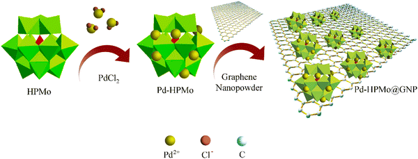
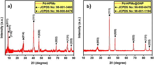
The ESI† provides a complete description of the synthetic process (Fig. 1). The characteristics of the synthesised samples were examined, and the findings are discussed in this section. The X-ray diffraction (XRD) analysis showed the existence of Pd, HPMo, and graphene nano-sheet-based nanocomposite in the Pd–HPMo and Pd–HPMo@GNP samples. Fig. 2(a) displays the obtained XRD pattern of Pd–HPMo, with several characteristic peaks located at 8°, 8.8°, 9.2°, 27.7° that can be indexed to the (011), (101), (110), (014) planes of phosphomolybdic acid in the anorthic crystal structure system, matching JCPDS No: 98-001-3460. Further, some other distinctive peaks were noted at 40.1°, 46.7°, 68.1°, 82.1°, and 86.6°, which could be assigned to the (111), (002), (022), (113), and (222) planes of palladium in the cubic crystal structure system, matching JCPDS No: 96-900-8479. For the Pd–HPMo sample, the characteristic peak of the Pd (111) lattice plane at 2θ = 40.1° was reasonably intense.31–33 Moreover, the characteristic high-intensity peak of HPMo at 2θ = 8° could be attributed to the (011) lattice plane. Besides, the characteristic diffraction peaks at 8.8°, 9.2°, and 27.7° could be attributed to the retained Keggin anion structure in Pd–HPMo. This provides initial evidence for the interaction of the Pd and MoOx species with HPMo.The XRD pattern of Pd–HPMo@GNP presented in Fig. 2(b) shows a characteristic peak positioned at 26.3°, which can be linked to the (003) plane of carbon in the hexagonal structure system, matching JCPDS No: 98-001-1194, and several representative peaks located at 40.1°, 46.7°, 68.1°, 82.1°, and 86.6°, which can be attributed to the (111), (002), (022), (113), and (222) planes of palladium in a cubic crystal structure system, matching JCPDS No: 96-900-8479. For the Pd–HPMo@GNP sample, the characteristic peak of the Pd (111) lattice plane at 2θ = 40.1° was reasonably intense.31–33 The π–π stacking between the graphene nanosheets results in a broad, less intense peak at ∼26.3°. Thus, the XRD pattern of Pd–HPMo@GNP provides initial evidence that the introduced HPMo was uniformly dispersed throughout the graphene nanosheets since no evident reflections related to the crystallographic planes of HPMo could be detected. The suppression of the other XRD peaks in Pd–HPMo@GNP is also indicative of the formation of a nanocomposite, as evidenced by the formation of a new peak matching the C (003) planes.
Furthermore, the Raman analysis also confirmed the occurrence of significantly reduced graphene in the Pd–HPMo@GNP composite. Raman spectroscopy is an effective technique to characterize graphitic nanomaterials, which exhibit poor crystallinity. The characteristic D and G bands of the sample appeared at 1352 cm−1 and 1595 cm−1, respectively. The intensity ratio of these bands of a sample indicates the degree of defect. The G band is indicative of the stretching mode of the graphite crystals, whereas the D band is typically associated with poor crystallisation. Because of the presence of crystalline graphene in Pd–HPMo@GNP, an increase in the D/G intensity ratio indicated that the average size of the sp2 domains had decreased in the composite. Fig. S1 (ESI†) depicts the Raman spectra of the Pd–HPMo@GNP and Pd–HPMo nanoparticles. The G band (1595 cm−1) associated with the in-plane vibration of sp2-bonded carbon atoms, and the D band (1352 cm−1) linked to the vibrations of carbon atoms in the graphene nanoparticles with an sp3 electronic configuration were detected following the addition of GNP to Pd–HPMo. These results are consistent with those of earlier reports.31,32,34
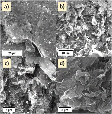
The morphology of the Pd–HPMo and Pd–HPMo@GNP materials were examined by SEM, FESEM, and TEM. The corresponding SEM images of the Pd–HPMo@GNP composite at different magnifications are shown in Fig. 3a–c. The dispersion of Pd–HPMo nanoparticles throughout the graphene nanosheet is visible in Fig. 3(a)–(c). The sheet-like structure of the graphene nanoparticles is apparent in Fig. 3(d). Upon the reduction of the Pd precursors to their metallic state, the ensuing Pd nanoparticles exhibit uniform deposition on the HPMo supports, facilitated by the strong association between Pd and HPMo. The HPMo species impede the aggregation of Pd nanoparticles, thus functioning as a protective agent in the process. Furthermore, the FESEM images also confirmed the successful formation of polycrystalline Pd–HPMo nanocuboids, as shown in Fig. S2(a) (ESI†). The images of the Pd–HPMo nanocomposite dispersed on graphene nanosheets at different magnifications are presented in Fig. S2(b) and (c) (ESI†).27 The energy-dispersive X-ray spectroscopy (EDS) data endorsed the presence of 1.97 atomic% of Pd in the Pd–HPMo nanocomposite, as shown in Fig. S2(d) (ESI†). HR-TEM analysis was done to obtain additional morphological insights into Pd–HPMo@GNP. Fig. 4(a) shows that palladium was encapsulated in HPMo, and Fig. 4(b) shows Pd–HPMo dispersed on graphene nanosheets.
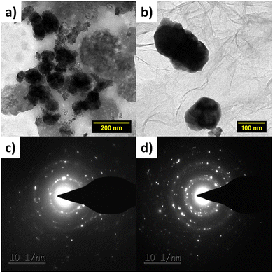 | ||
| Fig. 4 HRTEM images of (a) Pd–HPMo and (b) Pd–HPMo@GNP, and SAED patterns of (c) Pd–HPMo and (d) Pd–HPMo@GNP. | ||
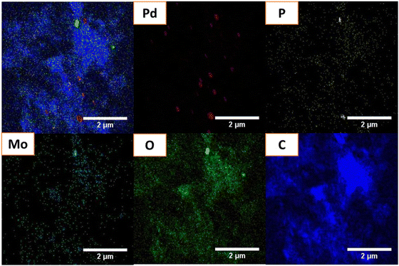
The SAED patterns in Fig. 4(c) and (d) demonstrate the extremely polycrystalline nature of Pd–HPMo and Pd–HPMo@GNP. The HRTEM images revealed that palladium nanoparticles, with a mean diameter of 3.45 nm, were evenly distributed on the GNP carrier, as shown in Fig. S3(c) (ESI†). The mean particle size of 3.8 nm reported previously is significantly bigger than this, indicating that the Pd NPs were polycrystalline.34 The elemental mapping of the Pd–HPMo and Pd–HPMo@GNP catalysts showed the homogeneous distribution of Pd particles on the support. Fig. 5 shows that the elements Pd, P, Mo, and O were evenly distributed on Pd–HPMo@GNP. The lattice fringe distances measured for the Pd nanoparticles were 0.21 and 0.24 nm, which are analogous to the (111) and (020) crystallographic planes of palladium, complementing the XRD results.
X-Ray photoelectron spectroscopy (XPS) was employed to determine the elemental composition and chemical valence of the complexes. The XPS of Pd–HPMo@GNP displayed peaks at 342.7 eV and 337.4 eV attributed to the Pd 3d3/2 and Pd 3d5/2, respectively. The binding energies of the Pd peaks were significantly higher than those of the metal composite Pd–HPMo peaks at 341.2 eV, 336 eV, and 338.8 eV. These findings substantiate the possibility of adsorption of the Pd nanoparticles on the GNP surfaces. Further, the chemical state information of the P, Mo, C, and O atoms were as follows: 133.6 eV for P 2p, 235.7 eV and 232.5 eV corresponding to the Mo 3d3/2 and Mo 3d5/2 orbitals, major C 1s peaks at 288.1, 285.8, 284.4 eV and those of O 1s at 533.1 and 530.6 eV, as shown in Fig. 6.35
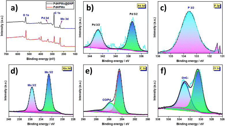 | ||
| Fig. 6 (a) XPS survey spectrum of Pd–HPMo@GNP and (b)–(f) the corresponding deconvoluted XPS spectra of Pd, P, Mo, C, and O. | ||
Electrocatalytic HER performance of Pd–HPMo and Pd–HPMo@GNP
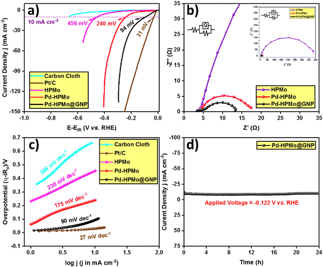
After extensive characterisation of the as-prepared materials using several analytical methods, the electrocatalytic activity of the as-prepared catalysts was examined using a three-electrode setup in a 0.5 M H2SO4 solution. Additionally, forward LSV was used to determine their activity (with 85% iR compensation) at a current density of 10 mA cm−2. The resultant LSV curves are presented in Fig. 7(a) along with the HER activity of the benchmark catalyst Pt/C for comparison. Notably, Pd–HPMo@GNP demonstrated a remarkably enhanced catalytic activity. Specifically, at a current density of 10 mA cm−2, Pd–HPMo@GNP exhibited an overpotential of 94 mV, while the standard catalyst Pt/C displayed an overpotential of 31 mV. Pd–HPMo displayed a low catalytic activity of 240 mV, while pristine HPMo displayed the least catalytic activity, i.e., pristine HPMo exhibited an overpotential of 456 mV to reach the same current density. The higher activity of Pd–HPMo@GNP than pristine HPMo can be ascribed to the enhanced electrical conductivity of the Pd ions and graphene. This also results in an increased number of electrocatalytic active sites, proving advantageous for the adsorption and desorption of H+ and H2 molecules, correspondingly. Furthermore, the EIS analysis of Pd–HPMo@GNP displayed a lower Rct value of 9.90 Ω at an applied potential of −0.222 V (vs. RHE) than both Pd–HPMo (13.54 Ω) and pristine HPMo (380.60 Ω), suggesting lower resistance for electron transfer at the electrode–electrolyte interface [Fig. 7(b)]. The inset in Fig. 7(b) shows the equivalent circuit of the resultant EIS curves (whole range). Moreover, the Tafel slopes were derived using the iR drop-free LSV polarization curves, and Fig. 7(c) illustrates these results. Compared with the Pd–HPMo (175 mV dec−1) and pristine HPMo (230 mV dec−1) catalysts, a much lower Tafel slope value of 90 mV dec−1 was estimated for Pd–HPMo@GNP, indicating quick electron transfer kinetics that can effectively surpass the kinetic barrier and enable superior HER performance. More importantly, Pt–C showed the lowest Tafel slope value of 27 mV dec−1.As presented in Fig. 7(d), chronoamperometric studies were carried out for a duration of 24 hours at an applied voltage of −0.122 V (vs. RHE) in order to verify the long-term static stability of Pd–HPMo@GNP. The chronoamperometric analysis revealed hardly any drop in current density, suggesting the extraordinary stability of Pd–HPMo@GNP in the 0.5 M H2SO4 electrolyte. Additionally, the overpotential was evaluated at various current densities, including 10, 50, and 100 mA cm−2. Fig. 8(a) shows the relevant results as a bar diagram, indicating the superior catalytic HER performance of Pd–HPMo@GNP to Pd–HPMo, even at greater current densities. The TOF of Pd–HPMo@GNP, Pd–HPMo and pristine HPMo were determined per unit active site per second. Pd–HPMo@GNP exhibited a higher TOF value of 1.397 × 10⁻⁴ s−1 than Pd–HPMo (3.080 × 10⁻⁵ s−1) and pristine HPMo (3.301 × 10⁻⁶ s−1) (Fig. 8b). This indicates that more active sites were involved in the production of H2 molecules in Pd–HPMo@GNP compared with the Pd–HPMo and pristine HPMo catalysts. Besides, the durability of the catalyst was evaluated by a CV test for 1000 consecutive cycles at a scan rate of 100 mV s−1. LSV was then measured, and Fig. S6 (ESI†) shows the observed outcomes. As illustrated in Fig. S6 (ESI†), the catalytic activity dropped with an overpotential difference of 15 mV in order to reach a current density of 50 mA cm−2. This may be because of the continuous CV cycles, which can lower charge accumulation at the active sites and consequently, the electrocatalytic HER activity of the sample.
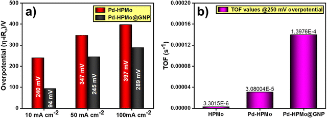 | ||
| Fig. 8 (a) Overpotential comparison of Pd–HPMo and Pd–HPMo@GNP at current densities of 10, 50, and 100 mA cm−2. (b) TOF of pristine HPMo, Pd–HPMo, and Pd–HPMo@GNP at a 250 mV overpotential. | ||
Further, several intrinsic parameters were examined in order to comprehend the reason for the better performance of Pd–HPMo@GNP than the Pd–HPMo catalyst. First, the roughness factor (Rf) and electrochemical active surface area (ECSA) of Pd–HPMo@GNP and Pd–HPMo were calculated by determining the double layer capacitance (Cdl) in a potential window of 0.125–0.227 V (versus RHE). Fig. S5(a)–(c) (ESI†) display the results of the Cdl plots. For the Pd–HPMo@GNP and Pd–HPMo samples, the obtained Cdl values were 2.11 mF cm−2 and 1.62 mF cm−2, respectively. After obtaining the Cdl values, the values of Rf and the ECSA were calculated using the formula Rf = Cdl/Cs, where Cs denotes the specific capacitance of the plane electrode surface (Cs = 0.035 mF cm−2), and ECSA = Rf × S, where S is the geometrical surface area of the working electrode (0.5 cm2). The determined Rf values for the Pd–HPMo@GNP and Pd–HPMo catalysts were 60.286 and 46.285, respectively, and the corresponding ECSA values were 30.143 cm2 and 23.143 cm2. The higher ECSA of Pd–HPMo@GNP than Pd–HPMo indicates its higher H2 generation potential. Further, Fig. S7 (ESI†) shows another chronoamperometric study conducted for a duration of 36 hours at a higher applied voltage of −0.250 V (vs. RHE) to experimentally verify and validate the long-term static stability of Pd–HPMo@GNP at higher current densities. This chronoamperometric analysis showed only a slight drop in current density, suggesting the extraordinary stability of Pd–HPMo@GNP in the acidic electrolyte medium even at higher current densities. Table S2 (ESI†) compares the electrocatalytic HER performance of different previously reported phosphomolybdic-acid-derived catalysts with Pd–HPMo and Pd–HPMo@GNP. The reported Tafel slope values and overpotentials at a current density of 10 mA cm−2 under similar and different electrolytic conditions obviously show that Pd–HPMo@GNP exhibits excellent electrocatalytic activity towards HER even with the least mass loading in comparison with other reported phosphomolybdic-acid-derived catalysts. The lower Tafel slope of Pd–HPMo@GNP and its lower overpotential to reach a 10 mA current density with just 0.1035 mg cm−2 loading mass shows its excellent efficiency in catalyzing the HER.
Post-electrocatalytic HER characterization of Pd–HPMo@GNP
Following the electrochemical HER catalytic studies, the durability of catalyst morphology and chemical composition was confirmed through various characterization techniques, including XRD, SEM, HR-TEM, and ICP-MS. Fig. S8 (ESI†) shows the XRD patterns of Pd–HPMo@GNP before and after chronoamperometric studies at an applied potential of −0.25 V (vs. RHE) for a duration of 36 hours (long-term stability test at a higher current density). The patterns distinctly indicate that the peaks remained consistent, thereby demonstrating that the catalyst retained its crystallinity. Fig. S9(a) and (b) (ESI†) display the SEM images of Pd–HPMo@GNP following the chronoamperometric experiments. The post-catalysis SEM images clearly depict Pd–HPMo dispersed in the sheet-like graphene structure, thereby confirming the preservation of catalyst morphology. Fig. S9(c) and (d) (ESI†) present the HR-TEM images of Pd–HPMo@GNP after the chronoamperometric studies. The HR-TEM images indicate that the morphology of Pd–HPMo@GNP remained intact, with the Pd–HPMo particles still uniformly dispersed, decorating the surface of the graphene nanosheets. To examine the leaching of palladium and molybdenum ions from the catalyst, ICP-MS analysis of the Pd–HPMo@GNP catalyst was conducted both before and after the chronoamperometric experimental analysis, as shown in Table S3 (ESI†). The initial concentrations of palladium and molybdenum were found to be 15.33 and 0.97 ppm, respectively, while the post-catalysis concentrations were 15.47 and 0.38 ppm, demonstrating negligible leaching of Pd from this composite. These results indicate that there was substantial leaching of Mo from the sample during catalysis, whereas Pd remained intact. Furthermore, the ICP-MS analysis revealed that only ∼15% of palladium was present in Pd–HPMo@GNP, corroborating our strategy of using a minimal amount of noble metal palladium in catalyst preparation. This approach ensures efficient performance, making the catalyst both cost-effective and viable for catalytic applications.Catalytic reduction of 4-nitrophenol to 4-aminophenol
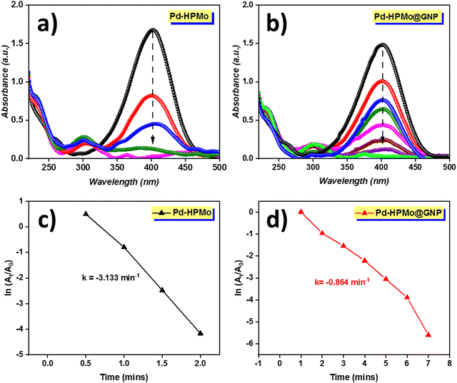
The catalytic reduction ability of the as-prepared nanocatalysts in the reduction of 4-NP to 4-AP was evaluated in the presence of a strong reducing agent NaBH4. Under normal circumstances, NaBH4 will not reduce nitro compounds to amines; however, in the presence of a nanocatalyst, NaBH4 performs this transformation in aqueous media. Due to its extreme toxicity, 4-nitrophenol is regarded as a hazardous solid waste. However, its reduced product, i.e., 4-aminophenol is frequently employed in the production of industrial and agricultural products, including colours, preservatives, insecticides, herbicides and medicines. As a result, it is critical to remove 4-NP from wastewater before it is discharged into potable water sources. Moreover, the presence of boron increases the toxicity of NaBH4 at higher concentrations; however, several research works have used larger doses of NaBH4 in comparison with 4-AP to achieve a faster reaction rate and a perfect fit to the pseudo-first-order reaction process, so that the reaction is so sluggish that it requires an efficient catalyst to enhance the electron transfer process. When stable and uniform-sized Pd NPs are synthesized, they dominate other metal nanoparticles in terms of catalytic efficiency towards converting 4-NP to 4-AP.In our investigation, it was found that self-assembled Pd NPs have significant catalytic 4-NP reduction efficiency in the presence of a hydrogen source. As seen in Fig. 9(a) and (b), the UV-vis absorption of 4-AP was observed at wavelengths 400 nm and 300 nm as a function of time in the presence of NaBH4 to evaluate the catalytic performance of Pd–HPMo and Pd–HPMo@GNP; the color of the solution instantly changed from bright yellow to deep yellow. During reduction, a decrease in peak intensity at 402 nm was observed over time; the complete disappearance of this peak specifies the completion of the reduction process. The UV-vis spectra of the solution containing the Pd–HPMo NP catalyst indicated that the reduction reaction of 4-NP was complete within 2 min, demonstrating its good catalytic activity (Fig. 9(a)).
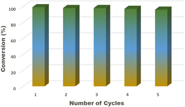
Meanwhile, Pd–HPMo@GNP took a slightly longer time (7 min) for complete conversion. Furthermore, the reusability of the Pd–HPMo catalyst was further investigated for five repeated catalytic cycles. The Pd catalyst could be recovered easily from the reaction mixture with no noticeable loss in activity even after 5 cycles, as shown in Fig. 10. In the recycling experiments, the time taken by the catalyst to reduce 4-nitrophenol significantly decreased compared to the first cycle. The kinetics of the reaction was estimated using the pseudo-first-order reaction kinetics equation,36 as follows:
| ln[At/A0] = kt |
Conclusion
This comprehensive study focused on advancing sustainable hydrogen production through water electrolysis by meticulously designing and exploring novel catalysts. In this work, we report the successful synthesis of the Pd–HPMo@GNP nanocomposite by a two-step wet chemical synthesis process using palladium chloride, phosphomolybdic acid, and graphene nanopowders as precursors. The successful encapsulation of palladium nanoparticles in the HPMo support, followed by their stabilization in the graphene nanosheets, was confirmed by surface morphological and elemental analyses using various characterization techniques, such as XRD, XPS, and HRTEM. The electrochemical analysis demonstrated the notable electrocatalytic activity of Pd–HPMo@GNP towards HER, with a lower overpotential of 94 mV vs. RHE at a current density of 10 mA cm−2 and a lower Tafel slope of 90 mV dec−1 than Pd–HPMo and HPMo, indicating fast electron transfer kinetics. Further, its robust stability during prolonged chronoamperometric studies for 24 h and a higher TOF value of 1.397 × 10⁻⁴ s−1 indicate the existence of a greater number of active sites for the generation of H2 molecules in the acidic electrolyte medium in comparison with its precursor Pd–HPMo and pristine HPMo. Further, the catalytic behavior of Pd–HPMo and Pd–HPMo@GNP towards the chemical transformation of toxic 4-nitrophenol to industrially useful 4-aminophenol was tested in the presence of NaBH4. They exhibited highly efficient catalytic activity with pseudo-first-order kinetics. In the presence of 120 mg NaBH4, 50 mL of 4-nitrophenol (0.43 mM) was completely reduced within 2 minutes and 7 minutes when 1 mg of Pd–HPMo and Pd–HPMo@GN were added, respectively, underscoring their potential for environmental applications. The outcomes of this research emphasize the pivotal role of catalyst design in overcoming thermodynamic and kinetic constraints inherent to large-scale water electrolyzers. Pd–HPMo@GNP emerges as a promising candidate, and it is comparable with the benchmark HER Pt/C catalyst as it offers enhanced catalytic activity and long-term stability and is cost-effective compared with the costly traditional Pt-based electrocatalysts. Incorporating phosphomolybdic acid (PMA) in graphene nanosheets provides a unique structural motif, contributing to the exceptional performance of the catalyst. The results underscore the significance of this work in advancing the development of sustainable catalysts for hydrogen evolution, with broader implications in electrochemical energy conversion systems. The synthesized nanocomposite demonstrates versatility in catalytic applications, such as HER and 4-NP reduction, marking a significant step towards environmentally conscious and energy-efficient technologies.Data availability
The authors confirm that the data supporting the findings of this study are available within the article and its ESI.†Conflicts of interest
The authors declare that they have no known competing financial interests or personal relationships that could have appeared to influence the work reported in this paper.Acknowledgements
S. I., A. V. and Dr M. K. would like to acknowledge CSIR New Delhi for the financial assistance through MLP-1004. The authors thank the Director and supporting staff CSIR-CECRI for the constant encouragement and support respectively. Central Instrumentation Facility Division, CSIR-CECRI is acknowledged for characterization facilities. The authors sincerely thank Mr Thomas Paul and Mr Gaurav Kapadnis, Centre of Excellence, Agilent Technologies India Pvt. Ltd, Bangalore, India for their timely analytical support in ICP-MS analysis. CECRI internal reference CECRI/PESVC/Pubs/2024-020.References
- S. Anantharaj, S. R. Ede, K. Sakthikumar, K. Karthick, S. Mishra and S. Kundu, ACS Catal., 2016, 6, 8069–8097 CrossRef CAS.
- M. Momirlan and T. N. Veziroglu, Renewable Sustainable Energy Rev., 2002, 6, 141–179 CrossRef CAS.
- M. Ni, M. K. H. Leung, D. Leung and K. Sumathy, Renewable Sustainable Energy Rev., 2007, 11, 401–425 CrossRef CAS.
- P. P. Edwards, V. L. Kuznetsov, W. I. F. David and N. P. Brandon, Energy Policy, 2008, 36, 4356–4362 CrossRef.
- Y. Zhao, B. Cao, Z. Lin and X. Su, Environ. Pollut., 2019, 254, 112961 CrossRef.
- A. Vijayaprabhakaran and M. Kathiresan, Mater. Adv., 2023, 4, 3593–3602 RSC.
- S. Sarkar and S. C. Peter, Inorg. Chem. Front., 2018, 5, 2060–2080 RSC.
- J. O. M. Bockris, Int. J. Hydrogen Energy, 2002, 27, 731–740 CrossRef CAS.
- C. Wang, H. Zhang, C. Feng, S. Gao, N. Shang and Z. Wang, Catal. Commun., 2015, 72, 29–32 CrossRef CAS.
- B. E. Barton and T. B. Rauchfuss, J. Am. Chem. Soc., 2010, 132, 14877–14885 CrossRef CAS.
- S. Li, Z. Liu, F. Wang, F. Yuan and Y. Ni, ACS Appl. Energy Mater., 2021, 4, 12836–12847 CrossRef CAS.
- S. Gopi, V. Selvamani and K. Yun, Inorg. Chem., 2021, 60, 10772–10780 CrossRef CAS PubMed.
- Z. W. Seh, J. Kibsgaard, C. F. Dickens, I. Chorkendorff, J. K. Nørskov and T. F. Jaramillo, Science, 2017, 355, eaad4998 CrossRef PubMed.
- J. Liang, Z. Cai, Z. Li, Y. Yao, Y. Luo, S. Sun, D. Zheng, Q. Liu, X. Sun and B. Tang, Nat. Commun., 2024, 15, 2950 CrossRef CAS.
- S. Shen, Z. Hu, H. Zhang, K. Song, Z. Wang, Z. Lin, Q. Zhang, L. Gu and W. Zhong, Angew. Chem., Int. Ed., 2022, 61, e202206460 CrossRef CAS PubMed.
- J. Zheng, Z. Shuyuan, S. Gu, B. Xu and Y. Yan, J. Electrochem. Soc., 2016, 163, F499–F506 CrossRef CAS.
- Z. Lin, B. Xiao, M. Huang, L. Yan, Z. Wang, Y. Huang, S. Shen, Q. Zhang, L. Gu and W. Zhong, Adv. Energy Mater., 2022, 12, 2200855 CrossRef CAS.
- L. Ouyang, X. He, Y. Sun, L. Zhang, D. Zhao, S. Sun, Y. Luo, D. Zheng, A. M. Asiri, Q. Liu, J. Zhao and X. Sun, Inorg. Chem. Front., 2022, 9, 6602–6607 RSC.
- J. Tang, X. Zhao, Y. Zuo, P. Ju and Y. Tang, Electrochim. Acta, 2015, 174, 1041–1049 CrossRef CAS.
- K. Kannimuthu, K. Sangeetha, S. Sam Sankar, A. Karmakar, R. Madhu and S. Kundu, Inorg. Chem. Front., 2021, 8, 234–272 RSC.
- X. Wang, M. Geng, S. Sun, Q. Xiang, S. Dong, K. Dong, Y. Yao, Y. Wang, Y. Yang, Y. Luo, D. Zheng, Q. Liu, J. Hu, Q. Wu, X. Sun and B. Tang, J. Mater. Chem. A, 2024, 12, 634–656 RSC.
- H. Jiang, M. Liu, M. Zhou, Y. Du and R. Chen, Ind. Eng. Chem. Res., 2021, 60, 15045–15055 CrossRef CAS.
- S. Niu, J. Yang, Q. Haifeng, Y. Su, Z. Wang, J. Qiu, A. Wang and T. Zhang, J. Energy Chem., 2020, 57, 371–377 CrossRef.
- N. Cheng, S. Stambula, D. Wang, M. N. Banis, J. Liu, A. Riese, B. Xiao, R. Li, T.-K. Sham, L.-M. Liu, G. A. Botton and X. Sun, Nat. Commun., 2016, 7, 13638 CrossRef CAS.
- S. A. Grigoriev, M. S. Mamat, K. A. Dzhus, G. S. Walker and P. Millet, Int. J. Hydrogen Energy, 2011, 36, 4143–4147 CrossRef CAS.
- A. Karmakar, K. Karthick, S. S. Sankar, S. Kumaravel, R. Madhu, K. Bera, H. N. Dhandapani, S. Nagappan, P. Murugan and S. Kundu, J. Mater. Chem. A, 2022, 10, 3618–3632 RSC.
- S. Ghasemi, S. R. Hosseini, S. Nabipour and P. Asen, Int. J. Hydrogen Energy, 2015, 40, 16184–16191 CrossRef CAS.
- S. Gu, Y. Lu, J. Kaiser, M. Albrecht and M. Ballauff, Phys. Chem. Chem. Phys., 2015, 17, 28137–28143 RSC.
- B. Zhang, H. Asakura and N. Yan, Ind. Eng. Chem. Res., 2017, 56, 3578–3587 CrossRef CAS.
- B. Zhang, H. Asakura, J. Zhang, J. Zhang, S. De and N. Yan, Angew. Chem., Int. Ed., 2016, 55, 8319–8323 CrossRef CAS PubMed.
- K. Szőri, R. Puskás, G. Szőllősi, I. Bertóti, J. Szépvölgyi and M. Bartók, Catal. Lett., 2013, 143, 539–546 CrossRef.
- A. H. Al-Marri, M. Khan, M. R. Shaik, N. Mohri, S. F. Adil, M. Kuniyil, H. Z. Alkhathlan, A. Al-Warthan, W. Tremel, M. N. Tahir, M. Khan and M. R. H. Siddiqui, Arabian J. Chem., 2016, 9, 835–845 CrossRef CAS.
- S. Wang, V. Fung, M. J. Hülsey, X. Liang, Z. Yu, J. Chang, A. Folli, R. J. Lewis, G. J. Hutchings, Q. He and N. Yan, Nat. Catal., 2023, 6, 895–905 CrossRef CAS.
- S. Yang, J. Dong, Z. Yao, C. Shen, X. Shi, Y. Tian, S. Lin and X. Zhang, Sci. Rep., 2014, 4, 4501 CrossRef PubMed.
- B. B. Li, S. Z. Qiao, X. R. Zheng, X. J. Yang, Z. D. Cui, S. L. Zhu, Z. Y. Li and Y. Q. Liang, J. Power Sources, 2015, 284, 68–76 CrossRef CAS.
- F. Bao, F. Tan, W. Wang, X. Qiao and J. Chen, RSC Adv., 2017, 7, 14283–14289 RSC.
Footnote |
| † Electronic supplementary information (ESI) available. See DOI: https://doi.org/10.1039/d4ma00256c |
| This journal is © The Royal Society of Chemistry 2024 |

