 Open Access Article
Creative Commons Attribution 3.0 Unported Licence
Toward high quality tactile sensors using ZnO/P(VDF-TrFE) flexible piezoelectric composite films
Sepide
Taleb
 *,
Wiebren M.
van Lingen
and
Mónica
Acuautla

Discrete Technology and Production Automation, Engineering and Technology institute Groningen, University of Groningen, Nijenborgh 4, 9747AG Groningen, The Netherlands. E-mail: s.taleb@rug.nl
First published on 6th September 2024
Abstract
In this research, ZnO/P(VDF-TrFE) piezoelectric composites are fabricated in different concentrations by two methods, spray coating and casting. Crystallinity, surface morphology, and piezoelectric performance of such films were analyzed and resulted in the optimal properties of 20 wt% ZnO in casted films (d33 = 48.93 pm V−1). The high sensitivity (18.5 mV N−1) of such piezoelectric films as tactile sensors was observed by performing two experiments, as a sensor in a gripping robot, and as a wearable device, monitoring the movement in the human arm. The research highlights the intricate relationship between crystallinity, β-phase content, piezoelectric coefficient, and sensor performance, underscoring the role of factors like stress distribution and mechanical behavior in determining overall efficacy.
1 Introduction
Currently, flexible and wearable electronics have become an emerging technology with a strong impact on different engineering fields. Motion monitoring (tactile sensing), health monitoring, wearable energy harvesting, storage systems, and electronic skin are some of the potential applications for this technology. According to the report of IDTecEX,1 an independent market research company, the market size for printed, flexible electronics will reach $12 billion by 2033, with the CAGR (compound annual growth rate) of 10%. Also, wearable technology devices’ market size has tripled between the years 2014 and 2022, and it is predicted to reach $161 billion by 2033.2 Reports of MarketsandMarkets website3,4 also corroborate this information, predicting CAGR of 8.8% and 18.0%, respectively for the mentioned fields.In this regard, piezoelectric transducers proved to be reliable, precise, and with a fast response in comparison to other sensors. Therefore, flexible piezoelectric materials, such as polyvinylidene fluoride (PVDF) and its copolymers have a huge potential in this growing market. Flexibility and high piezoelectric response in comparison to other polymer piezoelectric materials are some of the advantages of the PVDF family. On the other hand, inorganic piezoelectric thin films such as GaN5 or ZnO6 can provide notable piezoelectric properties, yet the fabrication complexity and cost often limits the widespread industrial fabrication. For further enhancement of both mechanical and piezoelectric performance, addition of piezoelectric nanofillers into polymer matrix is studied.7 ZnO nanoparticles, in particular, are a promising choice due to their piezoelectric properties, availability, low cost, and biocompatibility. This makes them ideal for wearable sensors and energy harvesters. Additionally, their optical properties open up exciting possibilities for developing piezo-opto devices.8
In recent research, various methods have been selected to fabricate ZnO/P(VDF-TrFE) composite films. Electrospinning is one of these methods that have been employed,9–11 and it mainly has resulted in higher β phase crystallinity, better mechanical properties, and higher specific surface area of fibers, but at the same time lower stress and strain.
Han et al.12 and Dodds et al.13 used spin coating method, and achieved higher piezoelectric coefficients, polarization values, dielectric constant, and β phase crystallinity in ZnO/P(VDF-TrFE) composite. This improvement was attributed to nanoparticles’ lower elasticity, increased internal stress, additional lateral potential fields, and static friction between ZnO particles and P(VDF-TrFE). However, Kim et al.14 observed decreased polarization values with added ZnO particles.
On the other hand, methods like spin coating and casting are best for academic research, but not suitable for industrial implementation. The potential for large-scale industrial fabrication is higher through the utilization of methods such as spray coating,15 microplotter printing and inkjet printing.16 In the recent studies, spray coating method has been successfully employed for fabrication of ZnO (microrods and flowers)/PVDF composite.17,18 In this work, we present enhanced ZnO/P(VDF-TrFE) films produced by a simple method. We study the effect of adding ZnO nanoparticles without any surface modification process to P(VDF-TrFE), proposing two methods; casting and ultrasonic spray coating.
Initially, casting method is employed to obtain the optimum concentration of ZnO particles based on characterization results. Crystallinity, morphology, ferroelectric and piezoelectric properties of such films with different concentrations, and application as sensors are presented. Later, the optimum concentration of ZnO is used for the fabrication of composite films using the spray coating approach, and the results are compared to the casting method. Spray coating method enables the industrial production of large, high quality, uniform piezoelectric films with high controllability and repeatability. To the best of our knowledge, this is the first study presenting fabrication of ZnO nanoparticle/P(VDF-TrFE) composite films using an uncomplicated ultrasonic spray coating deposition method with an enhanced piezoelectric properties and sensing performance. This study can facilitate the large-scale fabrication of composite polymer piezoelectric films, applicable to wearable sensors and soft robotics.
2 Materials and methods
Pristine P(VDF-TrFE) solution was made by mixing 0.25 g P(VDF-TrFE) (Solvene ®300/P300, Sigma-Aldrich), 3.5 ml N,N-dimethylformamide (anhydrous, 99.8%) (DMF), and 1.5 ml acetone. The mixture was stirred on the hotplate at 50 °C for 2 h. To prepare the composite solution, first zinc oxide particles (particle size < 50 nm, Mw = 81.39 g mol−1, Sigma-Aldrich) were dissolved in DMF and sonicated in an ultrasonic bath for 2 h. Simultaneously, P(VDF-TrFE) was dissolved in DMF![[thin space (1/6-em)]](https://www.rsc.org/images/entities/char_2009.gif) :
:![[thin space (1/6-em)]](https://www.rsc.org/images/entities/char_2009.gif) acetone (40
acetone (40![[thin space (1/6-em)]](https://www.rsc.org/images/entities/char_2009.gif) :
:![[thin space (1/6-em)]](https://www.rsc.org/images/entities/char_2009.gif) 60). This solution was stirred on a hotplate at 50 °C for 1 h. Afterwards, the ZnO solution was added drop by drop to the P(VDF-TrFE) solution, followed by 1 h stirring at 50 °C and 2 h ultrasonication for better distribution of ZnO particles. Different solutions with various concentrations of ZnO particles (10, 20, 30 wt%) were made in order to find an optimal concentration. However, the concentration of P(VDF-TrFE), DMF and acetone remained as the pristine solution.
60). This solution was stirred on a hotplate at 50 °C for 1 h. Afterwards, the ZnO solution was added drop by drop to the P(VDF-TrFE) solution, followed by 1 h stirring at 50 °C and 2 h ultrasonication for better distribution of ZnO particles. Different solutions with various concentrations of ZnO particles (10, 20, 30 wt%) were made in order to find an optimal concentration. However, the concentration of P(VDF-TrFE), DMF and acetone remained as the pristine solution.
For fabrication of piezoelectric films, solutions were casted on clean glass and annealed on a hotplate at 100 °C for 30 min. Then, the fabricated films with an average thickness of 20 μm were peeled off from the glass, and top and bottom silver electrodes, in shape of circles with the diameter of 2 mm, were added for characterization.
Final piezoelectric sensors were fabricated by spray coating method on a copper textile of 50 μm-thick, with the average thickness of 15 μm. In the end, 15 nm gold was sputtered on it as the top electrode. Selection of copper textile as the bottom electrode has been done for the ease of implementation as a wearable sensor. Finally, the electrical connections were made by copper wires and the sensors were encapsulated with PDMS. The final sensors have a thickness of ∼0.9 mm, and an active area of 63 mm2. None of the samples fabricated using casting and spray coating method were electrically poled.
3 Characterization
The crystalline structure of piezoelectric films was studied by Fourier transform infrared (FTIR) spectroscopy, using a Shimadzu's IRTracer-100, and X-ray diffraction analysis, using a Panalytical X’pert Pro MRD system. The diffraction scans were carried over 2θ = 10 to 80° range with Cu Kα of α = 1.5406 Å and steps of 0.02. The FTIR measurements were performed under ambient conditions in the range of 600 cm−1 to 2000 cm−1. For each spectrum, 32 scans at a resolution of 4 cm−1 were accumulated. Moreover, the morphology of the various films was observed by a scanning electron microscope (FeiNovaNano SEM 650) using high vacuum mode, with the voltage and spot size of 10 kV and 3.5, respectively. The thickness of films was measured by Veeco Dektak 150 Surface Profiler. The ferroelectric properties, including ferroelectric and displacement loops, were obtained by using a state-of-the-art aixACCT TF Analyzer 2000 ferroelectric-piezoelectric tester system. The dielectric constant was measured in the range of 20 to 2 MHz by an LCR Agilent E4980 with 16451B dielectric test fixture. The performance of these piezoelectric films as sensors in 33-mode was studied by applying different well controlled forces in the range of 10 to 100 N using an Instron Universal Mechanical System to emulate the fingertip forces during pressing.4 Results and discussion
4.1 Crystallography
The crystal structure of pristine and composite films, obtained by XRD, is illustrated in Fig. 1a from 10 to 80°. The only dominant peak for pristine film is located at 2θ = 19.8°, which is the characteristic peak of the (110) and (200) lattice planes of the β-phase P(VDF-TrFE). The intensity of this peak has been slightly decreased by increasing the concentration of ZnO particles in the composite films from 0 to 30 wt% ZnO. On the other hand, peaks relevant to the ZnO particles (COD 96-900-4182), including the ones at 2θ = 31.7°(010), 34.4°(002), 36.2°(011), became more intense in high concentration composite films, as expected.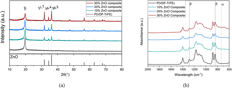 | ||
| Fig. 1 XRD (a) and FTIR (b) graph of P(VDF-TrFE) and composite films with various concentration of ZnO particles (10, 20, 30 wt%). | ||
For quantitative analysis of the β-phase crystallinity percentage, which is an effective parameter for piezoelectric performance, FTIR analysis was performed. Fig. 1b shows the absorbance spectra for various films. While absorbance peaks observed at 1286 cm−1 (for CF2 symmetric stretching vibration) and 842 cm−1 (for CH2 rocking, CF2 stretching and skeletal C–C stretching vibrations) are assigned to the β-phase, the signature bands of α phase P(VDF-TrFE) (613, 762, 795, 975 cm−1) are hardly noticeable.19,20
By applying Beer–Lambert law, the ratio of β phase to α phase (FEA) in each sample can be calculated using the equation below:19
 | (1) |
 | (2) |
| wt% ZnO | I 840 | I 763 | 1275 | 1260 | ΔHβ | 1234 | 1225 | ΔHγ | F EA | F(β) |
|---|---|---|---|---|---|---|---|---|---|---|
| 0 | 0.366 | 0.040 | 0.174 | 0.126 | 0.048 | 0.150 | 0.152 | 0.002 | 0.878 | 0.85 |
| 10 | 0.308 | 0.098 | 0.139 | 0.109 | 0.030 | 0.126 | 0.126 | 0.000 | 0.713 | 0.71 |
| 20 | 0.216 | 0.093 | 0.101 | 0.081 | 0.019 | 0.093 | 0.094 | 0.001 | 0.649 | 0.63 |
| 30 | 0.393 | 0.212 | 0.169 | 0.146 | 0.023 | 0.171 | 0.172 | 0.001 | 0.595 | 0.57 |
According to Table 1, the amount of β phase has decreased from 85% to 56% by increasing the concentration of ZnO particles. This implies that ZnO particles not only could not work as nucleating agent to enhance the β polar phase in the P(VDF-TrFE) but also, the β phase crystallinity percentage is reduced, contrary to the reports in some literature.9,11,12 Moreover, by comparing the FEA and F(β) values, it can be concluded that the amount of γ phase is negligible. These results are compatible with the data obtained by the XRD measurements. Addition of ZnO nanoparticles has disrupted polymer crystalline chain formation and alignment, possibly at the molecular level, thus resulting in a decrease in the β phase.
4.2 Morphology
Studying the morphology of composite films can provide us more information about the effect of nanofillers inside the P(VDF-TrFE) and the uniformity of its distribution. Fig. 2 shows the SEM images of the surface of films with 0 to 30 wt% ZnO nanoparticles. It is observed that the nanoparticles have been uniformly distributed in the P(VDF-TrFE) matrix for all the concentrations without any prior surface modification. However, some agglomeration is detected in the 30 wt% composite. The agglomeration can lead to some interfacial defects and poor mechanical properties, and accordingly lower piezoelectric performance.21 | ||
| Fig. 2 SEM images of P(VDF-TrFE) (a) and composite films with various concentration of ZnO particles [10 (b), 20 (c), 30 wt% (d)]. | ||
Furthermore, the polymer pattern observed in Fig. 2a for pristine P(VDF-TrFE) has been faded out by increasing the nanofillers concentration, till 30 wt% in which the pattern is totally disappeared. Previous research22,23 has shown the relationship between this pattern and the formation of the β polar phase in P(VDF-TrFE). Aligned with these reports, and according to FTIR, and XRD data, addition of ZnO particles has reduced the amount of β polar phase.
4.3 Piezoelectric properties
To study the piezoelectric properties of fabricated films, an electric field of 1000 kV cm−1 was applied to the films, and the average values of polarization and d33 coefficients were obtained. The ferroelectric, displacement, and current loops of pristine P(VDF-TrFE) and composites in Fig. 3 show the switching and saturation behaviour in all the films. As it is also shown in Table 2, there is no considerable difference between polarization values in various films. This is similar to the results obtained in ref. 14 for up to 20 wt% nanofillers in spin-coated samples. However, the higher coercive field of the 20 wt% composite is evident in the current loop (Fig. 3c). Moreover, considering the higher current peak of P(VDF-TrFE) and lower d33 implies the higher conductivity of the pure film.| wt% | Pr (μC cm−2) | Ps (μC cm−2) | Ec (kV cm−1) | d 33 (pm V−1) | Dielectric constant at 20 Hz | g 33 (mV m N−1) |
|---|---|---|---|---|---|---|
| 0 | 6.16 ± 1.56 | 8.34 ± 1.64 | 546 ± 28 | 44.2 | 8.8 | 567 |
| 10 | 5.60 ± 1.68 | 8.04 ± 1.83 | 519 ± 24 | 41.95 | 11.6 | 411 |
| 20 | 5.98 ± 0.84 | 7.65 ± 0.86 | 567 ± 27 | 48.93 | 12.8 | 432 |
| 30 | 6.24 ± 1.99 | 7.68 ± 1.99 | 542 ± 35 | 39.15 | 15.3 | 289 |
The 20 wt% composite film shows the highest d33 value of 48.93 pm V−1 in comparison to the pristine and other composite films. This is while the piezoelectric coefficient of commercial PVDF and P(VDF-TrFE) films can be enhanced by poling to up to 32 pm V−1.24,25 This enhancement is attributed to a unique stress and charge distribution obtained in this concentration. Additionally, ZnO nanoparticles might have introduced stress at the interface, inducing localized piezoelectric effects that contribute to the higher d33 value. This leads to achieving the highest piezoelectric voltage coefficient (g33) among composite films, which is in correspondence with the highest sensitivity of the sensor. Despite the higher remnant polarization of the 30 wt% composite film, a lower d33 value is obtained. This is associated with the agglomeration of ZnO particles observed in the SEM image (Fig. 2d). To confirm this observation, compression tests have been implemented.
4.4 Compression test and repeatability
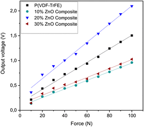
To characterize the sensing properties of the composite films, compression tests were performed using an Instron universal testing machine by applying forces in the range of 10 to 100 N (26 to 263 kPa) emulating the single touch of a fingerprint. The peak-to-peak voltage values normalized by thickness are shown in Fig. 4. All the samples show a high linearity with the R-squared value of the fitted regression line of more than 0.98. The sensitivity and the average output voltage produced for 20 wt% is 18.5 mV N−1, and 2.1 V by applying 100 N force, and are higher than the pristine P(VDF-TrFE) values (13.5 mV N−1, and 1.5 V at 100 N).Therefore, it can be observed that both the piezoelectric coefficient value and the piezoelectric voltage coefficient affect the performance of the final sensors. On the other hand, the crystallography characterization showed that the β phase percentage in 20 wt% films (63%) is lower than the pristine P(VDF-TrFE) (85%). Thus, the higher β phase percentage alone can not guarantee the better performance of flexible piezoelectric sensors and other factors such as stress distribution and mechanical properties are also of significance, and can affect the piezoelectric performance.7
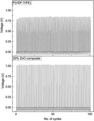
Other important characteristics to be considered in the fabrication of sensors are the reliability and repeatability of the results. To study the repeatability of the sensor, pristine P(VDF-TrFE) and 20 wt% composite films were exposed to 101 cycle 80 N (211 kPa) compression test (see Fig. 5). A slow increase in the voltage at the beginning of the consecutive cycles is observed for both films, which can be attributed to a waking up effect of the films. Thereafter, the voltage output remains stable at 0.909 V (with a standard deviation of 0.013 V), and 1.109 V (with the standard deviation of 0.007 V), for pristine P(VDF-TrFE) and 20 wt% composite films, consecutively. These results indicate good repeatability and reliability of both fabricated sensors.
5 Piezoelectric sensing test
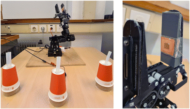
Piezoelectric sensors can be used in many applications, including robotics and touch sensors for wearable devices. In this section, the fabricated piezoelectric sensor is attached to the gripper of a AX18A Crustcrawler robotic arm, which has no feedback control, and the applied force by the gripper cannot be measured precisely. Incorporating an accurate piezoelectric sensor can provide the data for the feedback loop, without any additional power consumption. The setup of this experiment is shown in Fig. 6. The Gripper can be programmed to move to a predetermined position with a specific speed. Therefore, the applied force value is unknown. However, the torque of the motor can be observed during the gripping action.In this experiment, piezoelectric sensors were attached to one side of the gripper arm (as shown in Fig. 6), and three different sizes of silicon tubes (9.7, 13.3, 17 mm in diameter) were set on a table vertically. The robot arm grips and releases these silicon tubes one after the other. Since the final position of the gripper is predefined, it is expected to sense higher forces for the silicon tubes with a larger diameter. The output voltage obtained from this experiment for P(VDF-TrFE) and 20% ZnO composite sensor is shown in Fig. 7. A force sensitive resistor (FSR) sensor (Flexiforce-A201-Tekscan) was later attached to the gripper using the same setup to compare the force values with the voltage obtained from the piezoelectric sensors. The results show that 8, 10, and 15 N are the forces applied by the gripper to the small, medium and large tubes, respectively. Table 3 presents the motor torque, measured force, and obtained voltage from P(VDF-TrFE) and the 20% ZnO composite sensor. The results shown in Table 3 are aligned with the compression test, meaning higher output voltage was obtained from the 20% ZnO composite than the P(VDF-TrFE) sensors. Comparing the output voltage with the torque values and measured forces in Newton in Fig. 8, shows a better linearity in the 20 wt% ZnO composite results. Also, by calculating the euclidean distance between torque and output voltage in both cases, the 20 wt% composite showed a slightly higher compatibility between these two parameters.
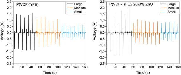 | ||
| Fig. 7 Output voltage of sensing robot arm for P(VDF-TrFE) and 20% ZnO composite with small (blue), medium (orange), and large (black) tube. | ||
| Tube size (diameter) | Measured force (N) | Torque (N m) | Produced voltage (V) | |
|---|---|---|---|---|
| P(VDF-TrFE) | 20 wt% ZnO composite | |||
| Small | 8 | 225 | 1.05 | 1.41 |
| Medium | 10 | 289 | 2.1 | 1.83 |
| Large | 15 | 385 | 2.78 | 3.43 |
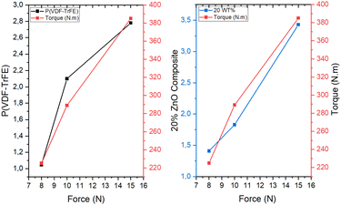 | ||
| Fig. 8 Comparing torque, force and output voltage of sensing robot arm for P(VDF-TrFE) and 20% ZnO composite with small, medium, and large tube. | ||
6 Spray coating method
Spray coating method was introduced in our previous study,15 and showed promising results for easy and low cost fabrication of PVDF films. However, to the best of the authors’ knowledge, spray coating method has not been used for the fabrication of wearable devices using P(VDF-TrFE) solutions containing particles. In this regard, the optimum sensors were also fabricated by the spray coating method on a copper textile to observe the possibilities of industrial, highly-uniform, large-scale fabrication of wearable sensors. The parameters of the spray coating system were based on the optimum values obtained in our previous study, except for the number of layers, which has to be higher due to the roughness of the copper textile. Table 4 compares the piezoelectric properties of a 15 μm-thick-film made by the spray coating method, using the solution containing 20 wt% ZnO nanoparticles in 20 layers with the previous casted sample. The deposition has been done on a hotplate at 50 °C, and there was a 40 second delay between each layer for the sake of drying. The average polarization values are compatible with the casted samples. However, the piezoelectric coefficient (d33) has been decreased.| Sample | Thickness (μm) | Pr (μC cm−2) | Ps (μC cm−2) | Ec (kV cm−1) | d 33 (pm V−1) |
|---|---|---|---|---|---|
| Spray coated | 15 | 5.3 ± 0.61 | 7.1 ± 0.66 | 576 ± 13 | 38.8 |
| Casted | 17 | 5.98 ± 0.84 | 7.65 ± 0.86 | 567 ± 27 | 48.93 |
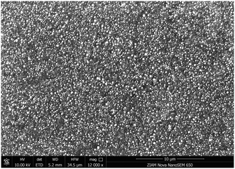
In Fig. 9, the surface morphology of the spray coated film is presented. As shown, most of the ZnO particles have been placed on top of the piezoelectric layer, and no agglomeration or sedimentation was observed.
Considering the lower d33 value of spray coated sample, it is possible that the addition of nanoparticles has interfered with the shear effect of the tube or transfer of ultrasound energy, and thus reduction of the piezoelectric effect. Additionally, particles might have increased the surface roughness, which can negatively affect the d33 value.15 Nevertheless, the polarization values do not show any decrease, and accounting for the different surface morphology of the spray coated sample, the different distribution of nanoparticles in the polymer would be the main cause of the lower performance of the spray coated sample. Even so, the overall uniformity of the spray coated samples and the capability of large-scale fabrication are advantages that can not be neglected.
Using this method, a wearable sensor was also made on the copper textile substrate, encapsulated with PDMS, and attached to the clothes in the the elbow area as shown in Fig. 10a. Attachment of a sensor to the clothes brings more comfort to the user and facilitates the monitoring of body motion. In Fig. 10b, the output voltage obtained by bending the elbow at a small (30°) and large angle (90°) is presented. According to these results, it can be concluded that, despite the lower piezoelectric properties of the spray coated sample in comparison to the casted ones, they can perform well in different applications, with the advantage of an easy and repeatable fabrication process.
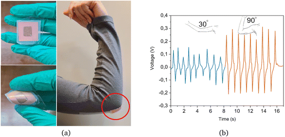 | ||
| Fig. 10 Piezoelectric sensor fabricated by spray coating and attached to the elbow (a), and output voltage obtained from moving the elbow in two different approaches (b). | ||
7 Conclusions
Flexible piezoelectric ZnO/P(VDF-TrFE) films were fabricated to be used as tactile sensors. Different fabrication methods (casting and spray coating) and concentrations of ZnO (0, 10, 20, 30 wt%) were studied. The piezoelectric films made by 20 wt% ZnO and using the casting method had the best piezoelectric coefficient of 48.93 pm V−1. However, it was observed that factors beyond nanoparticles concentration, such as stress distribution and mechanical characteristics also affected the performance. For both pure and composite samples, the repeatability tests for 100 cycles showed no change in the output. However, the sensitivity, linearity, and amplitude of voltage for the 20 wt% composite films were higher in tactile sensing and simple mechanical tests. Similar samples, fabricated using the spray coating method exhibited a different morphology and lower piezoelectric coefficient. Nonetheless, they proved effective in a wearable sensing experiment on the human elbow. In addition, spray coating, as a scalable fabrication method, presents opportunities for large-scale production. Uniformity, controllability, and repeatability are other advantages of the spray coating method. This study provides insights into the challenges and potential pathways for creating effective wearable sensors within the expanding field of flexible electronics.Data availability
The authors declare that the data supporting the findings of this study are available within the paper.Conflicts of interest
There are no conflicts to declare.Acknowledgements
This research was supported by the start-up grants of the FSE at the University of Groningen. The authors acknowledge the support of Taraneh Mokabber, Jacob Baas, Martin Stokroos, and Simon Busman in the lab.Notes and references
- Flexible, Printed and Organic Electronics 2020–2030: Forecasts, Technologies, Markets, https://www.idtechex.com/en/research-report/flexible-and-printed-electronics-2023-2033-forecasts-technologies-markets/943, Accessed: 2022-08-18.
- Wearable Technology Forecasts 2021–2031, https://www.idtechex.com/en/research-report/wearable-technology-forecasts-2023-2033/928, Accessed: 2022-08-18.
- Wearable Technology Market, https://www.marketsandmarkets.com/Market-Reports/wearable-electronics-market-983.html, Accessed: 2023-08-14.
- Flexible Electronics Market, https://www.marketsandmarkets.com/Market-Reports/flexible-electronics-market-50634885.html, Accessed: 2023-08-14.
- J. Chen, S. K. Oh, H. Zou, S. Shervin, W. Wang, S. Pouladi, Y. Zi, Z. L. Wang and J.-H. Ryou, ACS Appl. Mater. Interfaces, 2018, 10, 12839–12846 CrossRef CAS.
- P.-C. Lee, Y.-L. Hsiao, J. Dutta, R.-C. Wang, S.-W. Tseng and C.-P. Liu, Nano Energy, 2021, 82, 105702 CrossRef CAS.
- S. Taleb, M. Badillo, F. J. Flores-Ruiz and M. Acuautla, Sens. Actuators, A, 2023, 114585 CrossRef CAS.
- E. Nour, A. Echresh, X. Liu, E. Broitman, M. Willander and O. Nur, AIP Adv., 2015, 5, 077163 CrossRef.
- M. Kumar, et al. , J. Polym. Res., 2022, 29, 1–16 CrossRef CAS.
- B. Azimi, M. S. Sorayani Bafqi, A. Fusco, C. Ricci, G. Gallone, R. Bagherzadeh, G. Donnarumma, M. J. Uddin, M. Latifi and A. Lazzeri, et al. , Tissue Eng., Part A, 2020, 26, 1312–1331 CrossRef CAS PubMed.
- L. Ye, L. Chen, J. Yu, S. Tu, B. Yan, Y. Zhao, X. Bai, Y. Gu and S. Chen, J. Mater. Sci.: Mater. Electron., 2021, 32, 3966–3978 CrossRef CAS.
- J. Han, D. Li, C. Zhao, X. Wang, J. Li and X. Wu, Sensors, 2019, 19, 830 CrossRef PubMed.
- J. S. Dodds, F. N. Meyers and K. J. Loh, IEEE Sens. J., 2011, 12, 1889–1890 Search PubMed.
- T. Y. Kim, G. Anoop, Y. J. Son, S. H. Kim, E. Lee and J. Y. Jo, Phys. Chem. Chem. Phys., 2018, 20, 16176–16183 RSC.
- S. Taleb, M. A. Badillo-Ávila and M. Acuautla, Mater. Des., 2021, 212, 110273 CrossRef CAS.
- Y. Fang, H. Zou, S. Peng, G. Dong and M. M. Tentzeris, ACS Appl. Electron. Mater., 2023, 5, 4157–4167 CrossRef CAS.
- D. P. Ojha, B. Joshi, E. Samuel, A. Khadka, A. Aldalbahi, G. Periyasami, D. Choi, S. An and S. S. Yoon, Int. J. Energy Res., 2023, 2023, 3074782 CrossRef.
- B. Joshi, J. Seol, E. Samuel, W. Lim, C. Park, A. Aldalbahi, M. El-Newehy and S. S. Yoon, Nano Energy, 2023, 112, 108447 CrossRef CAS.
- X. Cai, T. Lei, D. Sun and L. Lin, RSC Adv., 2017, 7, 15382–15389 RSC.
- R. Sahoo, S. Mishra, L. Unnikrishnan, S. Mohanty, S. Mahapatra, S. K. Nayak, S. Anwar and A. Ramadoss, Mater. Sci. Semicond. Process., 2020, 117, 105173 CrossRef CAS.
- K. Shi, B. Chai, H. Zou, P. Shen, B. Sun, P. Jiang, Z. Shi and X. Huang, Nano Energy, 2021, 80, 105515 CrossRef CAS.
- R. Kishore, D. Singh, P. Kumar, R. Sriramdas, M. Sanghadasa and S. Priya, J. Phys.: Conf. Ser., 2019, 012023 CrossRef CAS.
- G. Suresh, G. Mallikarjunachari, S. Jatav, C. Thirmal, M. Ramachandra Rao and D. K. Satapathy, J. Appl. Polym. Sci., 2018, 135, 45955 CrossRef.
- R. Tao, J. Shi, M. Rafiee, A. Akbarzadeh and D. Therriault, Mater. Adv., 2022, 3, 4851–4860 RSC.
- G. Selleri, L. Gasperini, L. Piddiu and D. Fabiani, 2022 IEEE 4th International Conference on Dielectrics (ICD), 2022, pp. 90–93.
| This journal is © The Royal Society of Chemistry 2024 |


