
 Open Access Article
 This Open Access Article is licensed under a
 Creative Commons Attribution 3.0 Unported Licence
Soft PDMS-mediated formation of bovine serum albumin 3D coffee stain structures for reversible hydrophilic patterning†
Samuel Kok Suen
Cheng
,
Kimberly
Lopez
,
Maryam
Jalali-Mousavi
and
Jian
Sheng
 *
*
College of Engineering, Texas A&M University-Corpus Christi, Corpus Christi, TX 78412, USA. E-mail: jian.sheng@tamucc.edu
First published on 31st July 2024
Abstract
The evaporation of sessile drops containing non-volatile solutes produces a 2D ring-like deposition of particles at the contact line known as the coffee stain effect. In addition to 2D ring structures, evaporating protein drops can also produce 3D dome-shaped coffee stain structures (CSS) as well. In this study, a new 3D CSS, the buckling saddle-shaped film is reported when a bovine serum albumin (BSA) drop dries over a soft polydimethylsiloxane (PDMS) substrate. By systematically varying substrate wettability, elasticity, and protein concentrations, we have found that the saddle CSSs are only formed when an intermediate-concentration (1–10% w/v) BSA drop evaporates over a soft (<10 MPa) and hydrophobic substrate. Time-resolved epi-fluorescence microscopy of a BSA drop doped with fluorescently labeled BSA on a PDMS substrate reveals a new formation mechanism of the saddle CSS, which originated from subtle interplays of time scales of solvent evaporation, solute dispersion, and “skin” formation. Differing from the dome CSS, saddle CSS is formed by rapid “drainage” of the solution film between interfacial “skin” and substrate that leads to the asymmetrical distribution of BSA along the contract line and subsequently causes the interfacial “skin” to buckle as it dehydrates. We further discover that the abovementioned formation mechanism deposits a microscopically smooth thin protein film on the substrate underneath the drop. This discovery further inspires the proposed reversible hydrophilic patterning technique.
Introduction
The evaporation of sessile liquid drops with non-volatile solute particles (e.g. proteins, DNAs, nanoparticles, viruses, etc.) is a ubiquitous yet complex phenomenon that involves the intersection of fluid dynamics and thermodynamics.1 Evaporation will drive the solutes toward the contact line and produce a ring-shaped deposition known as the coffee ring or coffee stain.2 While the formation of coffee stains imposes an obstacle in many industrial processes such as inkjet printing3 or spray cooling4 and much research has been done on suppressing coffee stains,5 this phenomenon can also be exploited for self-assembling6 and concentrating7 particles.This exploitation of the coffee stain effect is of particular interest in biomedical fields when evaporating sessile drops contain biological entities such as viruses,8,9 bacteria,10,11 proteins,12,13 and exosomes.14,15 Wen et al. utilized the coffee stain effect to concentrate aptamer–thrombin complexes on a hydrophobic surface to achieve a 4-fold sensitivity increase for the detection of thrombin in diluted whole blood.16 Devineau et al. evaporated drops containing polystyrene particles and a pathogenic mutant form of human hemoglobin and found that pathogenic hemoglobin interacts differently with the microparticles to suppress the formation of the coffee stain structure (CSS). Rather it forms a uniform film that allows a quick visual test for the presence of pathogenic proteins.17 Besides forming the conventional 2D structures (e.g., ring and film), it has been reported that 3D CSS can be formed when evaporating protein-laden drops. Dogru et al. observed a 3D dome-shaped CSS when evaporating sessile drops containing green fluorescent protein (GFP)-doped silk fibroin drops on a superhydrophobic polydimethylsiloxane-urea (SHPSU) and the formation process is dependent on protein concentration. This 3D dome CSS is exploited as an all-protein amplifier to emit laser light at 547 nm when pumped with 5 ns optical parametric oscillator pulses at 482 nm.18
In this study, we report a new 3D “saddle-shaped” (or hyperbolic paraboloid film) CSS produced by evaporating sessile bovine serum albumin (BSA) drops over a soft polydimethylsiloxane (PDMS) substrate. By systematically investigating the effect of substrate elasticity, BSA concentration, and surface wettability, we have found that the new 3D “saddle-shaped” CSS is an intermediary structure that can be only generated by a drop with moderate BSA concentrations (1–10%) over PDMS substrates with low stiffness (0.3–10 MPa). Real-time imaging of the entire formation process using BSA drops doped with fluorescently labeled BSA proteins reveals a new formation mechanism that is based on the subtle interplays of time scales of solvent evaporation, solute dispersion, and interfacial “skin” formation.
It is further found that differing from 3D dome-shaped CSSs, the saddle-shaped CSS is formed by rapid “drainage” of the solvent film between the interfacial protein “skin” at the air–liquid interface and the soft substrate that leads to the asymmetrical distribution of BSA proteins along the contract line and subsequently causes the interfacial protein “skin” to buckle in the direction normal to the substrate as it dehydrates. Furthermore, we have discovered that this rapid drainage deposits a microscopically smooth thin protein film over the substrate, which leads to the proposed low-cost, robust, and reversible hydrophilic patterning technology.
Results and discussion
Observation of a new saddle-like CSS over soft substrates
When a 4 μL sessile BSA drop at 5% w/v BSA concentration is evaporating over a soft PDMS surface with a monomer-to-curing agent (MTC) ratio of 10![[thin space (1/6-em)]](https://www.rsc.org/images/entities/char_2009.gif) :1, the drop reduces its apex height significantly in the beginning (Movie S1, ESI†). As evaporation continues, the buckling of the interfacial “skin” in the direction normal to the wall is initiated at the contact line and propagated radially inward to the center where the particulate concentration is low, whereas the buckling film is anchored firmly on the surface at the locations of high protein concentrations. Owing to the symmetry, the buckled film has two “anchors” and two lifted sides (Fig. 1A and Movie S1, ESI†). This is in great contrast with evaporating a drop of the same volume on a standard glass slide, in which case a typical 2D ring structure19 is observed (Fig. 1B and Movie S2, ESI†). Upon closer inspection, the film has the shape of a hyperbolic paraboloid (i.e., a saddle) with one negative and one positive plane of principal curvatures (Fig. 1C and D). By measuring directly the Gaussian curvatures, we confirm that this 3D CSS is a hyperbolic paraboloid since it has a negative Gaussian curvature.20 Interestingly, the buckling process also removes debris on the PDMS surface, making the surface smoother than the original PDMS surface (Fig. S1, ESI†).
:1, the drop reduces its apex height significantly in the beginning (Movie S1, ESI†). As evaporation continues, the buckling of the interfacial “skin” in the direction normal to the wall is initiated at the contact line and propagated radially inward to the center where the particulate concentration is low, whereas the buckling film is anchored firmly on the surface at the locations of high protein concentrations. Owing to the symmetry, the buckled film has two “anchors” and two lifted sides (Fig. 1A and Movie S1, ESI†). This is in great contrast with evaporating a drop of the same volume on a standard glass slide, in which case a typical 2D ring structure19 is observed (Fig. 1B and Movie S2, ESI†). Upon closer inspection, the film has the shape of a hyperbolic paraboloid (i.e., a saddle) with one negative and one positive plane of principal curvatures (Fig. 1C and D). By measuring directly the Gaussian curvatures, we confirm that this 3D CSS is a hyperbolic paraboloid since it has a negative Gaussian curvature.20 Interestingly, the buckling process also removes debris on the PDMS surface, making the surface smoother than the original PDMS surface (Fig. S1, ESI†).
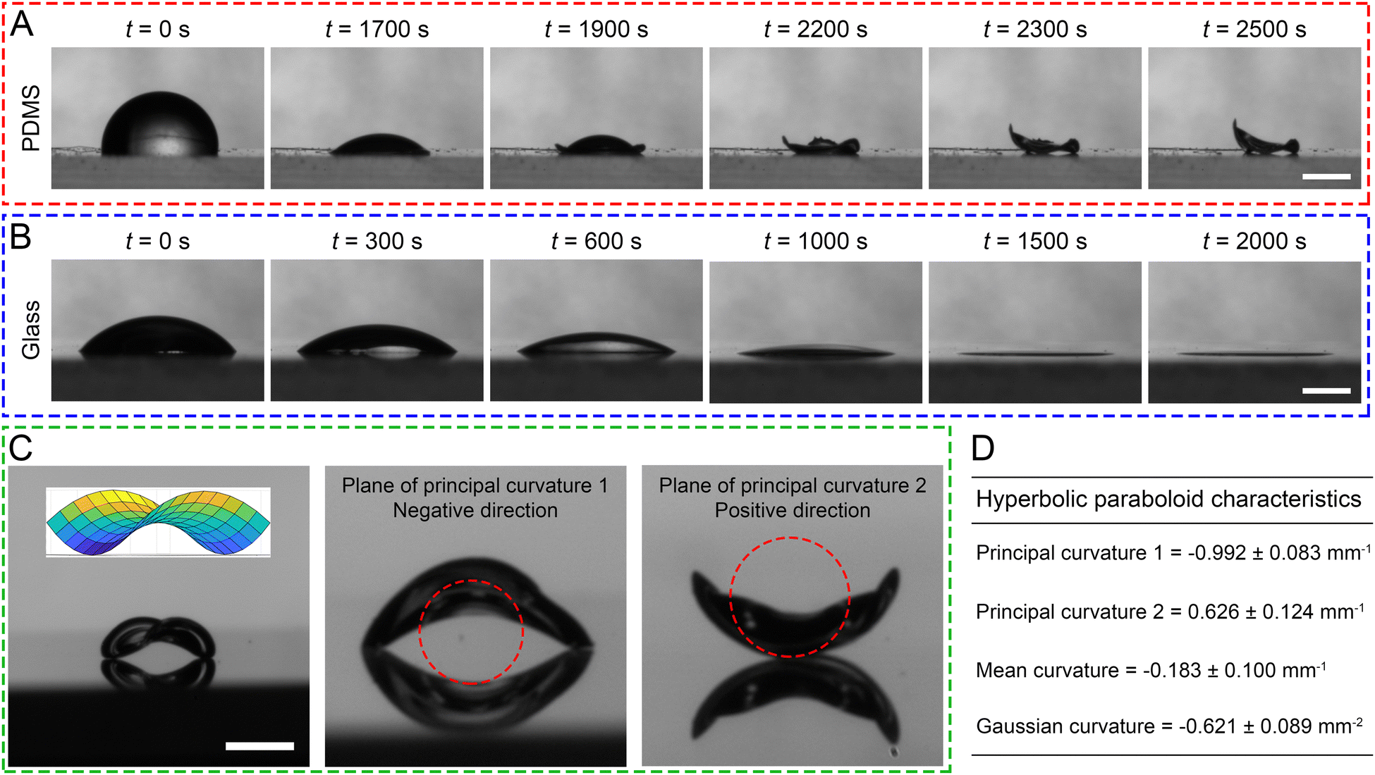 | ||
| Fig. 1 Timelapse micrographs of a 4 μL 5% w/v BSA sessile drop evaporating over a (A) PDMS to form a hyperbolic-paraboloid protein film (or a 3D dome CSS) and (B) glass substrate to form a 2D ring CSS. (C) Closeups of the hyperbolic-paraboloid film viewed at planes of the orthogonal principal curvatures of the same CSS in (A). Inset: Computer model of a buckling hyperbolic paraboloid film with measured geometric parameters (D). The standard deviation is calculated from three replicates. Scale: 1 mm. | ||
Parameters affecting 3D CSS formation
To elucidate the underlying mechanism, we investigate the formation of the abovementioned 3D CSS by systematically varying parameters (Fig. 2) such as drop volume (Fig. 2A), surface wettability (Fig. 2B), surface stiffness (Fig. 2C), and BSA concentration (Fig. 2D). For clarity, we only show the results from two diametrically different conditions for each effect here and leave the itemized results for each parameter in (Fig. S2–S7, ESI†). To examine the effect of the drop volume, we vary the volume from 2 to 16 μL but fix the BSA concentration at 5% (w/v). As expected in the absence of inertia, all drops form saddle CSSs with larger drops requiring longer time (Fig. 2A and Fig. S2, ESI†). Results support our assertion that the formation of this “saddle-shaped” CSS is independent of drop size but strongly associated with the substrate properties (e.g. substrate wettability and elasticity).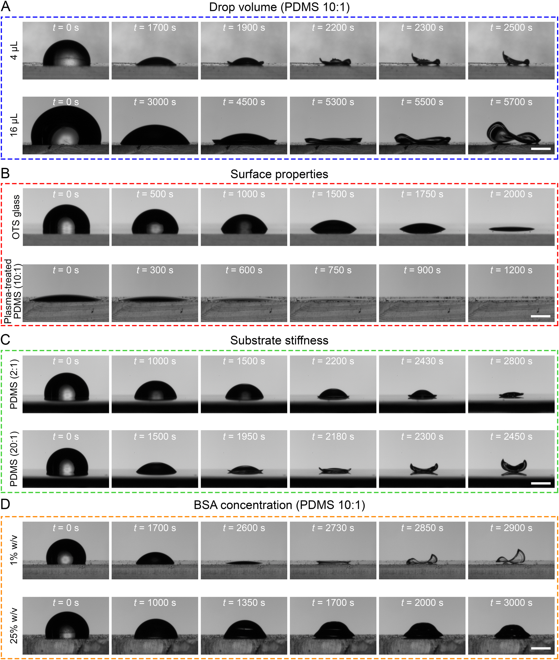 | ||
| Fig. 2 Timelapse images of evaporating BSA drops and the formation of the final coffee stain structures under the effect of (A) drop volume, (B) substrate wettability, (C) substrate stiffness, and (D) BSA concentration. Scale: 1 mm. | ||
To explore the roles of substrate properties in 3D CSS formation, we have prepared samples by permuting the surface hydrophobicity and stiffness. We use (soft or <10 MPa) PDMS and (rigid) glass to explore substrate stiffness, while we use surface functionalization to alter surface energy. We synthesize the octyltrichlorosilane (OTS) self-assembled monolayer (SAM) to make an originally hydrophilic (rigid) glass substrate hydrophobic, while O2 plasma treatment is applied to alter the hydrophobic (soft) PDMS substrate to be hydrophilic. For simplicity, we will use prefixes (OTS–) and (O2–) to indicate the surface functionalization hereinafter and followed by substrate materials (e.g. glass, PDMS). Note after functionalization, PDMS and OTS-glass are hydrophobic with comparable contact angles (Fig. S3, ESI†). It is shown anecdotally that despite the compatible surface energy of PDMS and OTS-glass, the saddle CSS is only formed on the PDMS substrate (Fig. 2B and Fig. S4A, C, ESI†). This observation implies that a soft, deformable substrate is necessary to form a saddle CSS, whereas rigid substrates inhibit this process. When comparing a hydrophobic PDMS substrate with a hydrophilic O2—PDMS, a typical 2D ringlike CSS is formed on the hydrophilic O2—PDMS (Fig. S4A and D, ESI†), suggesting that the low surface energy (or hydrophobic) plays a crucial role in this unique buckling process.
For the case of (hydrophilic) glass and (hydrophobic) OTS-glass (rigid), both cases form 2D ring CSS (Fig. S4B and C, ESI†). Collectively, one may conclude that the observed saddle-shaped CSS can only be formed on a soft substrate with low surface energy (e.g. PDMS).
To examine the effect of substrate elasticity, we conduct experiments using thick (>1.5 mm) PDMS substrate over a glass slide with varying bulk elasticity. The PDMS bulk elasticity, E is modulated by varying MTC ratios, ranging from the softest 20:1 (E = 0.27 MPa) to the stiffest 2:1 (E ≈ 15 MPa). It is observed that a 5% w/v BSA drop evaporating on the softer PDMS (20:1 and 10:1) will form saddle-shaped CSSs (Fig. 2C), whereas on stiffer PDMS (5:1 and 2:1) a dome-shaped CSS is observed (Fig. 2C and Fig. S5, ESI†). This 3D dome CSS is described as a small dome buckling at the periphery (e.g. “lips”) and containing a vacuole (or void) in the middle near the substrate (Fig. S6 and Movie S3, ESI†). This dome CSS has been reported by Dogru et al. using silk fibroin drops on a superhydrophobic SHPSU surface.18
Lastly, the effect of protein concentration is investigated (Fig. 2D) using a BSA drop over 10:1 PDMS. As BSA concentrations change from 0.01% to 25% w/v, a CSS structural transition is clearly observed. At low concentrations (e.g., 0.01–0.1%) the 2D ring CSS is obtained, whilst 3D dome CSS is formed at high concentrations (e.g., 10–25%). The newly observed 3D saddle-shaped CSS is formed at medium concentrations of 1–5% (Fig. S7, ESI†). Contrary to Dogru et al. results of silk fibroin protein drops forming conventional 2D coffee rings on a PDMS substrate at 7–9% w/v concentration,18 BSA at equivalent concentrations can only form 3D structures (e.g. dome or saddle, Fig. S7, ESI†). Since 3D CSS structure is only observed in BSA drops but not in silk fibroin drops, we speculate that structures of protein particles are also expected to contribute to the final CSS. An analogous mechanism can be drawn from the results by Yunker et al. that drops containing ellipsoidal particles form uniform 2D films in comparison to rings formed by drops containing spherical particles.21
Compounding current and prior studies, we identified four types of CSSs: 2D ring, 2D uniform attached film, dome-shaped 3D film, and saddle-shaped 3D film. For brevity, we hereinafter refer to them as ring, film, dome, and saddle CSS.
Regimes
The results above reveal that surface energy, substrate elasticity, and particulate characteristics (e.g. concentrations and shape) affect the ultimate CSS type. Although changing the PDMS surface energy by polyethylene oxide22,23 is possible, systematically varying PDMS surface energy without altering its surface chemistry is difficult. Hence, the current study focuses just on the effects of substrate elasticity and protein concentrations using the native hydrophobic PDMS substrates. Atomic force microscopy (AFM) confirms an increase in the elastic modulus with a decreased MTC ratio (Fig. S8 and Table S1, ESI†). The regime diagram of identified CSSs for a BSA drop over a PDMS substrate is shown in Fig. 3. Three distinct regimes are observed: (1) 2D ring, (2) 3D saddle, and (3) 3D dome. Within the ring and saddle regions, the periphery of the ring and saddle film is not always smooth but has spikes protruding outwards for stiffer PDMS substrates (i.e., 5:1 and 2:1 MTC ratios). The partition lines are drawn qualitatively here due to the lack of resolution in experiment parameters.
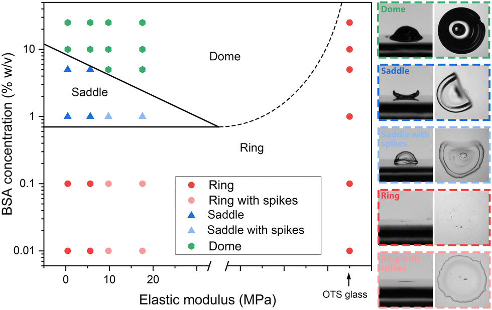 | ||
| Fig. 3 Regime diagram of final CSSs of an evaporating BSA drop on PDMS with respect to BSA concentration and elastic modulus of PDMS. Insets: Side and top closeups of identified CSSs. Scale: 1 mm. | ||
To investigate the asymptotic behaviour at very stiff substrates, we deposit BSA drops of various concentrations ranging from 0.01% to 25% w/v on OTS-glasses and record the CSS. Only the ring CSS is observed on the OTS-glass for all concentrations (Fig. S9, ESI†). Results suggest that as the elastic modulus of the substrate increases towards the rigid regime (∼GPa range), the final CSS transits from dome to ring structure without going through the transient regime of saddle. While this study truncated at 25% concentration, future investigation of CSS formed at higher BSA concentrations is necessary.
Formation of CSSs over PDMS substrates
To further understand the formation process of BSA CSSs (i.e. dome and saddle) over a soft substrate, we use the solution with normal BSA proteins at various concentrations (e.g. 0.01–25% w/v) doped with fluorescently labelled BSAs as tracers and 10:1 PDMS substrates. Note that due to the altered structures of labelled BSA, drops containing only labelled BSA produce different CS structures in comparison to its unlabelled counterpart. For example, a pure 5% w/v labelled BSA drop forms an attached 2D thin film with cracks in the middle (Fig. S10, ESI†), which agree well with literatures.24 After careful experimentation, we have found that an unlabelled BSA solution premixed with a 5% v/v labelled solution produces the same CS structures and generates sufficiently strong fluorescent signal. Note that 5% v/v refers to the concentration of the labelled BSA to the total BSA including both unlabelled and labelled BSA. To produce such a mixture, both labelled and unlabelled BSA solutions are made independently at desired concentrations (e.g., 0.01%, 5%, and 25% w/v). The 5% v/v labelled BSA solution is then mixed with 95% v/v to generate the final mixture for experiments. Protein distribution during evaporation is visualized (Fig. 4A) by a fluorescent microscope (Nikon TiE).
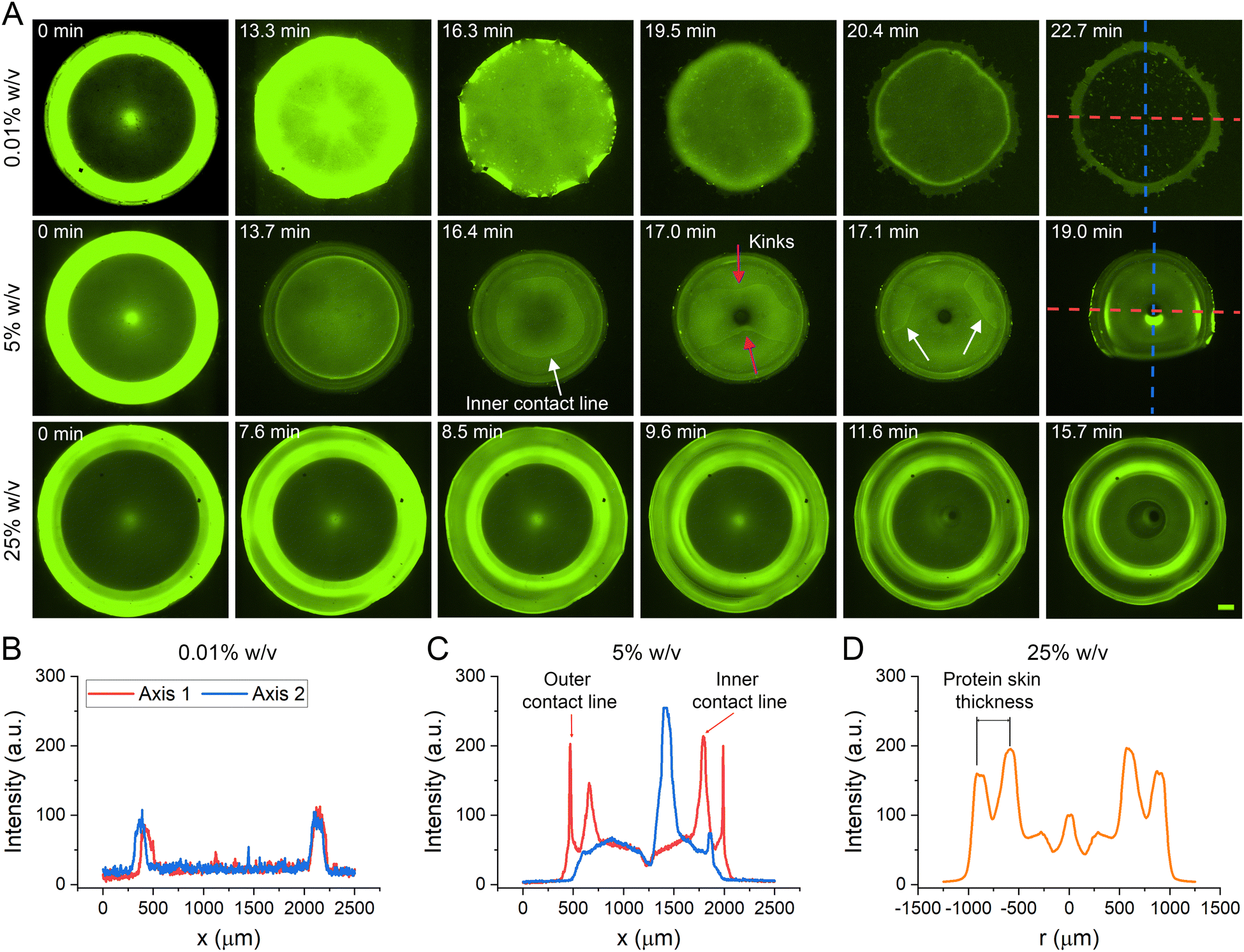 | ||
| Fig. 4 (A) Timelapse epi-fluorescent micrographs of evaporating drops of 0.01%, 5%, and 25% w/v BSA doped with fluorescently labeled BSA at 5% v/v with respect to total BSA over a 10:1 PDMS substrate. Scale: 100 μm. Intensity profiles along two orthogonal sampling lines marked in (A) for concentrations of (B) 0.01%, (C) 5%, and (D) mean radial intensity profile of a BSA drop averaged over the azimuthal direction. A.U. – arbitrary units. | ||
Besides protein concentration, the substrate elasticity also affects CSS formation (Fig. 2C and 3). To understand the formation mechanism, we measure the evolution of drop topology (e.g. normalized apex height, H(t)/Ho, and drop base diameter) on PDMS substrate with different elasticity (Fig. S12, ESI†) by varying the MTC ratio. The evaporation rate quantified as the temporal gradient of H(t)/Ho increases negatively with the substrate elasticity, i.e., a BSA drop on a stiffer substrate evaporates slower (Fig. S12A, ESI†), where the trend agrees well with that for a DI water drop.28 Differing from the evaporation processes involving a drop with nanoparticles (NPs) over a rigid substrate29 that there are two identified evaporation modes, i.e. constant contact radius (CCR)29,30 where outer contact line remains pinned during the evaporation, and a mixed mode where both drop apex height and radius of the outer contact line decreased simultaneously.30 We have clearly observed both modes of evaporation occurring in the sequence for a BSA drop evaporating over a soft substrate, more importantly such a phased evaporation depends highly on substrate elasticity. For substrates stiffer than 20:1 PDMS, we have observed that a BSA drop evaporates in CCR mode first, followed by a mixed mode. Just before the formation of CSS, evaporation mode reverts to CCR (Fig. S12B, ESI†). For a 20:1 PDMS substrate, BSA drop evaporates in CCR mode only. The trend of transitioning from the mixed mode to the CCR mode of evaporation as the PDMS substrate becomes softer is consistent with the literature.31
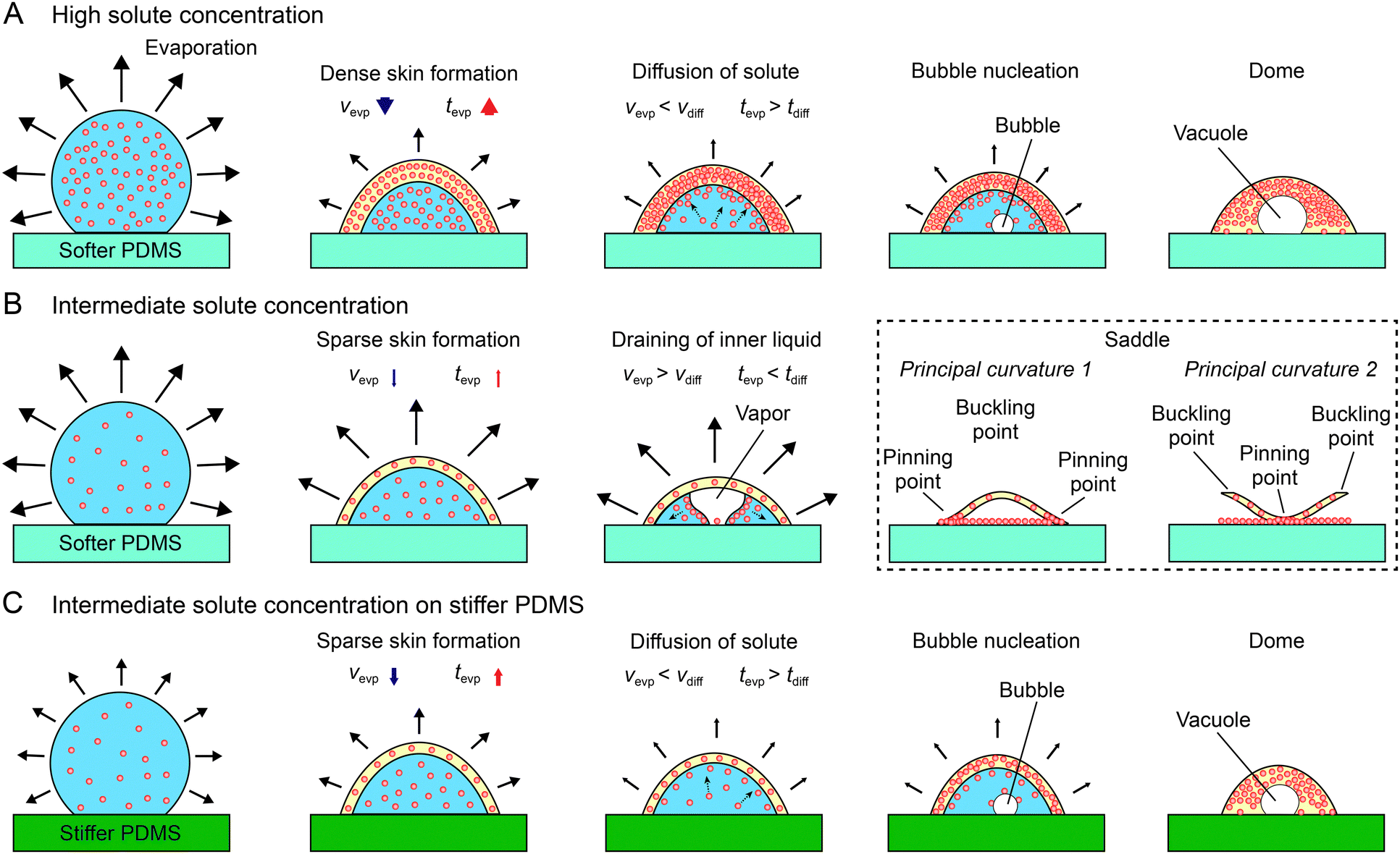 | ||
| Fig. 5 Mechanisms to form (A) dome CSS under high solute concentration and over soft PDMS, (B) saddle CSS under intermediate solute concentration and over soft PDMS, and (C) dome CSS under intermediate solute concentration and over a stiff PDMS. Solid black arrows denote the evaporation rate and dotted arrows denote BSA dispersion. The change in the evaporation and diffusion rates and timescales are denoted by blue and red arrows with the thickness of the arrows representing the relative magnitude. | ||
In the case of high BSA concentration (Fig. 5A), initial evaporation will cause BSA proteins to migrate towards the air–liquid interface and form a protein skin. Owing to its high solute concentration, a thick protein skin will be formed that consequently reduce the evaporation rate (Vevp) of solute1,35 or increase tevp. This slowed solvent evaporation in comparison to solute diffusion (e.g. tevp > tdiff) causes the continued deposition of BSA proteins at the inner surface of the skin to grow radially inward, essentially allowing the skin to be constantly in contact with the contracting solvent. Eventually, a vacuole is formed in the inner cavity leading to the final dome CSS. It is worth noting that the abovementioned model mandates the vacuole to be initiated and formed “on” the solid substrate and dome wall to be thick. The corroborative anecdotal evidence is shown in Fig. 4D and Fig. S11 (ESI†).
In the scenario of intermediate BSA concentration (Fig. 5B), a protein skin is also formed initially, but due to the lower BSA concentration, the skin formed is less dense in comparison to the high concentration scenario. This sparse skin impedes the evaporation less (e.g. tevp < tdiff), which causes the solvent to contract faster than the protein skin does. As the evaporation proceeds, the sparse skin deforms and collapses to form a thin solvent film. As evaporation continues, the film kinks and drains like a capillary film toward the contact line (Fig. 4A, middle row). As the skin dehydrates, it buckles and form the saddle CSS.
We further examine the validity of the proposed mechanism in the scenario of a BSA drop of an intermediary concentration over varying substrate stiffness (Fig. 5C). In this scenario, although concentration mediated protein skin remains thin, solvent evaporation is modulated by substrate stiffness,28i.e. a stiffer substrate deforms less to accommodate the smaller pinning stresses at the three-phase contact line and subsequently reduces Vevp. Such a substrate stiffness mediated solvent evaporation yields sufficient reduction of Vevp in comparison to that of solvent diffusion, i.e. Vevp < Vdiff, such that the solvent is unable to be separated from the protein skin, and form a dome CSS, following the scenario of the high BSA concentration.
Additionally, the conventional 2D ring/film CSS can also be explained by this proposed mechanism. Since the 2D ring/film occurs only for low solute concentrations, the protein skin formed is very thin or does not form at all. Throughout the drying process, the evaporation rate remains faster than the diffusion rate and enables the collapse of the drop interface towards the solid substrate. At the same time, Deegan flow pushes the solutes toward the drop boundary25 to form the conventional 2D ring CSS (Fig. 4A, top row).
Reversible hydrophilic patterning with a saddle CSS
Owing to the unique formation mechanism of a saddle CSS, a thin film of protein is deposited over the PDMS directly underneath the CSS as thin film between substrate and protein skin drains rapidly and asymmetrically towards the contact line (3rd–5th panels in the mid-row of Fig. 4A). We speculate that the deposited protein film on substrate is submicron in thickness since phase contrast and differential interference contrast microscopy at 550 nm as well as interferometry at 632 nm yields no visible roughness or topological features on the surface.We exploit this unique means of depositing hydrophilic protein thin film without affecting substrate roughness to perform hydrophilic patterning. Fig. 6A showcases the patterning process and its validation result. The patterning is: (i) deposit a 5% BSA drop over a 10:1 PDMS substrate, (ii) evaporate to form a saddle CSS (Panel 1 in Fig. 6A), (iii) remove CSS by a tweezer or compressed air (Panel 2 in Fig. 6) and results in a “visually pristine” substrate (Panel 3 in Fig. 6A). Simple validation is performed by rinsing DI water over the surface (Panel 4 in Fig. 6A). After the drainage of surface water, a sessile water drop is pinned and formed over the area which coincides precisely with where the saddle CSS is formed (Panel 5 in Fig. 6A), strongly suggesting hydrophilic modification of the substrate (Movie S7, ESI†). Note the water drop assumes the contact line of the original patterning BSA drop. We validate our patterning technique with respect to substrate stiffness (e.g. 20:1, 10:1, 5:1, and 2:1 respectively) using a 5% w/v BSA drop. As demonstrated in the first two insets of Fig. 6B, water drops are clearly trapped and formed over soft substrates after rinsing (e.g. 20:1 and 10:1 PDMS, where saddle CSSs are formed). It is worth noting that patterning fails completely over stiffer substrates (e.g. 5:1 and 2:1 PDMS) where dome CSSs are developed, i.e. no trapped water drops are formed after rinsing. We further measured the trapped water drop contact angle of 24.5 ± 2.2° and 45.7 ± 5.6° for 20:1 and 10:1 PDMS substrates, respectively (Fig. 6B). This reduction in hydrophilicity provides further anecdotal but quantitative evidence to support our CSS formation and subsequent patterning mechanism that rapid drainage/evaporation of liquid film between protein skin and substrate over protein diffusion towards the interface facilitates thin film deposition and subsequent patterning. For instance, protein drops on a softer PDMS has a shorter evaporation timescale (Fig. S12A, ESI†) than the solute diffusion timescale. Consequently, this disparity between timescales causes solutes to remain in the liquid between the skin and substrates and subsequently deposited over the substrate as the film drains. The larger the disparity, the more proteins are deposited and the more effective the patterning. Comparing the adhered water drops on 20:1 and 10:1 PDMS showed that while they have the same diameter (Fig. S13A, ESI†), the apex height and drop volume are much larger for drops on 10:1 PDMS substrate than those on 20:1 PDMS (Fig. S13B and C, ESI†). These results contrast with the study by Iqbal et al. who showed that a softer PDMS leads to the deposition of polystyrene particles onto the substrate with a larger spacing between particles (i.e., fewer particles given the same area) during drying.36 This highlights the difference between simple microparticles that do not undergo the sol–gel transition and biomolecules such as BSA that undergo the sol–gel transition to form protein skins which can alter the final particle distribution pattern on the solid soft substrate.
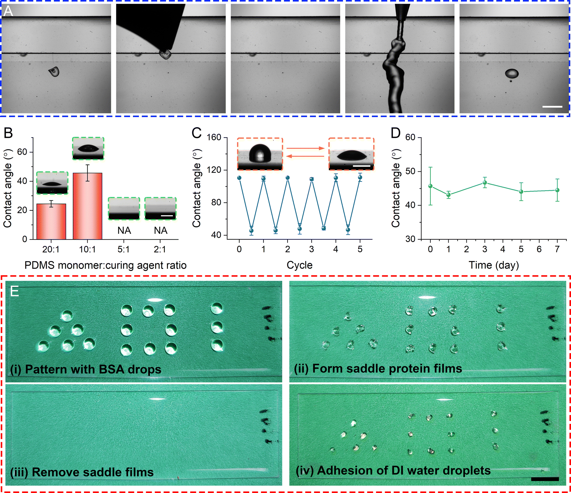 | ||
| Fig. 6 (A) Timelapse images depicting an adhesion of a DI water droplet on the spot where the saddle protein film had formed. (B) Characterization of the adhered DI water contact angle with respect to the PDMS stiffness. Insets show the adhered DI water droplets. (C) The variation of the DI water contact angle after multiple rounds of hydrophilic and hydrophobic transformation. Insets show the two states of the DI water droplets on hydrophobic and hydrophilic PDMS surfaces. Scale bar: 1 mm. (D) The DI water contact angle tested up to 7 days after removing the saddle protein film. (E) Hydrophilic patterning via the evaporation of the BSA droplets and removal of the saddle protein films on a 10:1 PDMS substrate. Three different shapes are shown here: a pyramid, a square, and a line. Scale: 1.5 cm. | ||
We find that this patterning method is highly reversible whereby physical abrasion with wipes to remove adsorbed BSAs and rinsing with DI water will render the patterned areas hydrophobic again and ready to repeat patterning again. This process can be repeated many times. Fig. 6C demonstrates the surface energy of the patterned area by measuring DI water contact angle for 5 patterning-removal cycles are clearly bimodal and highly reversible. Furthermore, the patterned surface has at least one-week shelf life (Fig. 6D).
Proof-of-concept hydrophilic patterning via saddle CSSs is performed using 5% BSA drops over a 10:1 PDMS substrate. Fig. 6E and Fig. S14 (ESI†) show the patterning process by depositing BSA drops on PDMS with various shapes and arrangement with a micropipette. After removing the saddle CSSs and dipping the patterned PDMS into dyed DI water, locations where there is a BSA film have water drop adhered to it, forming a similar pattern as the initial BSA drop arrangements. The rest of PDMS surface remained hydrophobic.
The proposed patterning method is robust and applicable to a wide range of substrate stiffness. More importantly, it is an low-cost and simple method for hydrophilic patterning without expensive processes, such as lithography,37 plasma jet,38 UV,39 and laser irradiation.40 The proposed method only requires a micropipette, and this is useful in resource-limited situations.
Implications of reversible patterning with evaporation
The proposed patterning technique exploits the subtle interplays between solvent evaporation and solute mobility in an evaporating drop containing proteins to deposit a protein thin film over the substrate without visibly modifying surface topology. Since the technique explores a robust mechanism in a niche regime of CSS formation occurring in many colloidal systems, parameter spaces (i.e. surface stiffness, hydrophobicity, and solute concentration) are particularly broad and potentially applicable to a wide range of surface materials, solutes, and solvents other than aqueous protein solutions on PDMS. More importantly, the proposed method is particularly simple and robust to operate at low cost, since patterns can be controlled by drop deposition and spatial resolutions can be determined by drop size, both of which can be achieved by recent technology advancements in 3D printing.41 In comparison to existing patterning methods including stamping, the proposed technique is particularly simple and repeatable.Conclusions
A new 3D coffee stain structure (CSS), the buckling hyperbolic paraboloid film (saddle CSS), is observed for an evaporating BSA sessile drop on a soft PDMS substrate. The formation of this buckling protein film is dependent on the concentration of BSA, wetting properties, and the elasticity of the substrate. The regime diagram reveals that the newly discovered saddle structure is a transitional structure occurring at intermediary protein concentration and on a hydrophobic soft substrate. Further experiments using epi-fluorescent microscopy and BSA solution doped with labelled BSA protein show that the competition between solvent evaporation and solute diffusion controls the final CSS topology, based on which we propose a unified formation mechanism covering 2D ring/film, 3D dome and saddle CSS. Focusing on 3D CSS on soft substrates, we conclude that the formation of protein skin at the air–liquid interface and the interplay of skin mediated time scales between solvent evaporation and solute diffusion play a crucial role in determining final CSS. Elucidated in detail above and summarized here: To form 3D dome CSS, a protein skin formed at the air–liquid interface reduces the evaporation rate (Vevp), making it less than the protein diffusion rate (Vdiff). This allows suspended proteins time to migrate toward the porous interface (skin) and subsequently grow radially inward a new inner layer of the skin. Except for the time when a vacuole is formed at the end of the process, the inner surface of the skin is continuously wetted. The observation of a vacuole being located at the substrate supports our assertion on the fully wetted inner skin interface. To form a saddle CSS, a thin “skin” is formed at the beginning in comparison to a thick one to form a dome. The thin skin reduces Vevp so slightly that Vevp remains larger than Vdiff, i.e. evaporation is still faster than diffusion, which causes a rapid drainage of the liquid film established between the skin and the substrate. Rapid drainage also causes partial separation of skin and film and leads to asymmetric drainage towards the contact line to form “anchors”. Owing to this rapidly (<1 min) receding film, suspended particles are deposited onto the substrate. Optical microscopy confirmed that the deposited layer is microscopically smooth. To our delight, we can utilize this unique mechanism to perform low-cost hydrophilic patterning of a soft PDMS substrate by drops. This proposed patterning method is found to be repeatable and easily reversible, potentially wide applications in biomedical and surface engineering.Experimental
Fabrication of PDMS
A standard glass slide is first cleaned with DI water, acetone, methanol, isopropanol, and DI water again. The glass slide is then dried with N2 gas and placed on a hot plate set to 120 °C for 10 min. PDMS monomer is mixed with the curing agent at monomer-to-crosslinker ratios of 2:1, 5:1, 10:1, or 20:1 thoroughly, degassed in a desiccator, and then cast onto the cleaned glass and allowed to be pinned at the slide edge. The PDMS is then cured on a 60 °C hot plate (PC-400D, Corning) for at least 48 hours. To create the hydrophilic PDMS, the cured PDMS is plasma etched for 3 min using a plasma cleaner (PDC-32G, Harrick Plasma).
Imaging
The BSA drops are deposited onto the PDMS surface using a micropipette and the environment is controlled at a temperature of 22 °C and a relative humidity of 40%. The side view of the evaporating drop is imaged with an in-house developed goniometer that consists of a projection lens (AF Nikkor 105 mm, Nikon) connected to a CCD camera (CLB-B2021M-TF000, Imperx) and a silhouette light source. Top view bright field micrographs are imaged using an inverted microscope at 4× (Eclipse TS100, Nikon) and an upright microscope at 10× (Eclipse LV150NA, Nikon). DIC and fluorescent images are captured using an inverted fluorescent microscope (Eclipse Ti, Nikon) connected to an EMCCD camera (DU-888U3-CS0-BV, Andor) with the latter using an exposure time of 500 ms and a FITC filter cube. PDMS substrates after hydrophilic patterning are imaged using a smartphone camera.Hydrophilic surface characterization
After the formation of saddle-shaped protein film from a 5% w/v BSA drop on a 10:1 PDMS substrate, the film is first removed from the surface using a tweezer. Next, a pipette is used to flow 300 μL of DI water through the place where the protein film was located. Immediately, the trapped DI water drop is imaged using the above in-house developed goniometer. For the characterization of the repeatability, a fixed reference point is first marked on the bottom of the pinned PDMS, and all subsequent experiments are done on this reference point. A 5% w/v BSA sessile is deposited on top of the reference point and let to evaporate, forming the buckling protein film. The hydrophilicity is then tested using the abovementioned rinsing procedure, after which the PDMS surface is wiped down using Kim wipes and rinsed with DI water twice, before depositing another DI water drop on top of the reference point. The water contact angle is then measured. The cycle is repeated 5 times. To characterize the stability of this hydrophilic transformation method, a 5% w/v BSA drop is evaporated on a 10:1 PDMS surface and the saddle-shaped film is removed from the substrate using a tweezer. The PDMS is then kept in a closed Petri dish for the required days before the test.
Author contributions
Samuel Kok Suen Cheng: conceptualization, investigation, methodology, visualization, writing – original draft, writing – review & editing. Kimberly Lopez: investigation, methodology, writing – review & editing. Maryam Jalali-Mousavi: resources, methodology, writing – review & editing. Jian Sheng: conceptualization, funding acquisition, project administration, supervision, writing – original draft, writing – review & editing.Data availability
Data will be made available upon request.Conflicts of interest
There are no conflicts to declare.Acknowledgements
This research was partially supported by ARO under grant no. W911NF-20-1-0307, ONR under grant no N00014-21-1-2834 and under grand no N00014-23-1-2242, as well as Cancer Prevention Research Institute for Texas (CPRIT) under grant no. RP200593. Microfabrication and material characterization instrument was partially supported by ARO under grant no. W911NF-17-1-0371. Authors also wish to acknowledge Mr Sreedathan Menon's contribution to perform patterning experiments as a high school intern and his support from Army Education and Outreach Program (AEOP).References
- D. Zang, S. Tarafdar, Y. Y. Tarasevich, M. Dutta Choudhury and T. Dutta, Evaporation of a Droplet: From physics to applications, Phys. Rep., 2019, 804, 1–56 CrossRef CAS.
- M. Yang, D. Chen, J. Hu, X. Zheng, Z.-J. Lin and H. Zhu, The application of coffee-ring effect in analytical chemistry, TrAC, Trends Anal. Chem., 2022, 157, 116752 CrossRef CAS.
- J. Park and J. Moon, Control of colloidal particle deposit patterns within picoliter droplets ejected by ink-jet printing, Langmuir, 2006, 22, 3506–3513 CrossRef CAS PubMed.
- X. Yu, J. Li, Y. Mo, T. Xiang, Z. Ku, F. Huang, F. Long, Y. Peng and Y.-B. Cheng, “Coffee ring” controlment in spray prepared >19% efficiency Cs0.19FA0.81PbI2.5Br0.5 perovskite solar cells, J. Energy Chem., 2022, 67, 201–208 CrossRef CAS.
- D. Mampallil and H. B. Eral, A review on suppression and utilization of the coffee-ring effect, Adv. Colloid Interface Sci., 2018, 252, 38–54 CrossRef CAS PubMed.
- W. Han and Z. Lin, Learning from “coffee rings”: ordered structures enabled by controlled evaporative self-assembly, Angew. Chem., Int. Ed., 2012, 51, 1534–1546 CrossRef CAS PubMed.
- Y. Wang, F. Liu, Y. Yang and L.-P. Xu, Droplet evaporation-induced analyte concentration toward sensitive biosensing, Mater. Chem. Front., 2021, 5, 5639–5652 RSC.
- R. Gebhardt, J.-M. Teulon, J.-L. Pellequer, M. Burghammer, J.-P. Colletier and C. Riekel, Virus particle assembly into crystalline domains enabled by the coffee ring effect, Soft Matter, 2014, 10, 5458–5462 RSC.
- Q. Huang, W. Wang and P. J. Vikesland, Implications of the Coffee-Ring Effect on Virus Infectivity, Langmuir, 2021, 37, 11260–11268 CrossRef CAS PubMed.
- W. Sempels, R. De Dier, H. Mizuno, J. Hofkens and J. Vermant, Auto-production of biosurfactants reverses the coffee ring effect in a bacterial system, Nat. Commun., 2013, 4, 1757 CrossRef PubMed.
- T. Andac, P. Weigmann, S. K. P. Velu, E. Pinçe, G. Volpe, G. Volpe and A. Callegari, Active matter alters the growth dynamics of coffee rings, Soft Matter, 2019, 15, 1488–1496 RSC.
- M. Shaw, A. Bella and M. G. Ryadnov, CREIM: Coffee Ring Effect Imaging Model for Monitoring Protein Self-Assembly in Situ, J. Phys. Chem. Lett., 2017, 8, 4846–4851 CrossRef CAS PubMed.
- S. Choi and G. Birarda, Protein Mixture Segregation at Coffee-Ring: Real-Time Imaging of Protein Ring Precipitation by FTIR Spectromicroscopy, J. Phys. Chem. B, 2017, 121, 7359–7365 CrossRef CAS PubMed.
- H. Jeong, C. Han, S. Cho, Y. Gianchandani and J. Park, Analysis of Extracellular Vesicles Using Coffee Ring, ACS Appl. Mater. Interfaces, 2018, 10, 22877–22882 CrossRef CAS PubMed.
- H. Jeong, H. Shin, J. Yi, Y. Park, J. Lee, Y. Gianchandani and J. Park, Size-based analysis of extracellular vesicles using sequential transfer of an evaporating droplet, Lab Chip, 2019, 19, 3326–3336 RSC.
- J. T. Wen, C. M. Ho and P. B. Lillehoj, Coffee ring aptasensor for rapid protein detection, Langmuir, 2013, 29, 8440–8446 CrossRef CAS PubMed.
- S. Devineau, M. Anyfantakis, L. Marichal, L. Kiger, M. Morel, S. Rudiuk and D. Baigl, Protein Adsorption and Reorganization on Nanoparticles Probed by the Coffee-Ring Effect: Application to Single Point Mutation Detection, J. Am. Chem. Soc., 2016, 138, 11623–11632 CrossRef CAS PubMed.
- I. B. Dogru, C. Kosak Soz, D. A. Press, R. Melikov, E. Begar, D. Conkar, E. N. Firat Karalar, E. Yilgor, I. Yilgor and S. Nizamoglu, 3D coffee stains, Mater. Chem. Front., 2017, 1, 2360–2367 RSC.
- M. Parsa, S. Harmand and K. Sefiane, Mechanisms of pattern formation from dried sessile drops, Adv. Colloid Interface Sci., 2018, 254, 22–47 CrossRef CAS PubMed.
- Q. Wang, M. M. Trubyanov, D. V. Andreeva and K. S. Novoselov, Nanoarchitectonics of hyperbolic paraboloid 2D Graphene Oxide Membranes, Z. Anorg. Allg. Chem., 2021, 647, 2073–2079 CrossRef CAS.
- P. J. Yunker, T. Still, M. A. Lohr and A. G. Yodh, Suppression of the coffee-ring effect by shape-dependent capillary interactions, Nature, 2011, 476, 308–311 CrossRef CAS PubMed.
- H. Chen, Z. Zhang, Y. Chen, M. A. Brook and H. Sheardown, Protein repellant silicone surfaces by covalent immobilization of poly(ethylene oxide), Biomaterials, 2005, 26, 2391–2399 CrossRef CAS PubMed.
- M. Yao and J. Fang, Hydrophilic PEO-PDMS for microfluidic applications, J. Micromech. Microeng., 2012, 22, 025012 CrossRef.
- L. Yin, W. Wang, S. Wang, F. Zhang, S. Zhang and N. Tao, How does fluorescent labeling affect the binding kinetics of proteins with intact cells?, Biosens. Bioelectron., 2015, 66, 412–416 Search PubMed.
- R. D. Deegan, O. Bakajin, T. F. Dupont, G. Huber, S. R. Nagel and T. A. Witten, Capillary flow as the cause of ring stains from dried liquid drops, Nature, 1997, 389, 827–829 CrossRef CAS.
- M. Yu, C. Le Floch-Fouéré, L. Pauchard, F. Boissel, N. Fu, X. D. Chen, A. Saint-Jalmes, R. Jeantet and L. Lanotte, Skin layer stratification in drying droplets of dairy colloids, Colloids Surf., A, 2021, 620, 126560 CrossRef CAS.
- V. V. Berejnov, Self-pinning protein-laden drops, J. Colloid Interface Sci., 2008, 322, 246–251 CrossRef CAS PubMed.
- V. Charitatos and S. Kumar, Droplet evaporation on soft solid substrates, Soft Matter, 2021, 17, 9339–9352 RSC.
- S. K. Wilson and H.-M. D'Ambrosio, Evaporation of Sessile Droplets, Annu. Rev. Fluid Mech., 2023, 55, 481–509 CrossRef.
- Y.-S. Yu, Z. Wang and Y.-P. Zhao, Experimental and theoretical investigations of evaporation of sessile water droplet on hydrophobic surfaces, J. Colloid Interface Sci., 2012, 365, 254–259 CrossRef CAS PubMed.
- R. Iqbal, A. Matsumoto, A. Q. Shen and A. K. Sen, Understanding the Role of Loss Modulus of Viscoelastic Substrates in the Evaporation Dynamics of Sessile Drops, Langmuir, 2024, 40, 10035–10043 CrossRef CAS PubMed.
- R. Iqbal, B. Majhy, A. Q. Shen and A. K. Sen, Evaporation and morphological patterns of bi-dispersed colloidal droplets on hydrophilic and hydrophobic surfaces, Soft Matter, 2018, 14, 9901–9909 RSC.
- R. Iqbal, A. Q. Shen and A. K. Sen, Understanding of the role of dilution on evaporative deposition patterns of blood droplets over hydrophilic and hydrophobic substrates, J. Colloid Interface Sci., 2020, 579, 541–550 CrossRef CAS PubMed.
- A. Fortini, I. Martín-Fabiani, J. L. De La Haye, P.-Y. Dugas, M. Lansalot, F. D’Agosto, E. Bourgeat-Lami, J. L. Keddie and R. P. Sear, Dynamic Stratification in Drying Films of Colloidal Mixtures, Phys. Rev. Lett., 2016, 116, 118301 Search PubMed.
- B. Sobac and D. Brutin, Structural and evaporative evolutions in desiccating sessile drops of blood, Phys. Rev. E: Stat., Nonlinear, Soft Matter Phys., 2011, 84, 011603 Search PubMed.
- R. Iqbal, A. Matsumoto, A. Sudeepthi, A. Q. Shen and A. K. Sen, Substrate stiffness affects particle distribution pattern in a drying suspension droplet, Appl. Phys. Lett., 2019, 114, 253701 CrossRef.
- K. Tsougeni, D. Papageorgiou, A. Tserepi and E. Gogolides, “Smart” polymeric microfluidics fabricated by plasma processing: controlled wetting, capillary filling and hydrophobic valving, Lab Chip, 2010, 10, 462–469 RSC.
- J. Liu, J. Song, G. Wang, F. Chen, S. Liu, X. Yang, J. Sun, H. Zheng, L. Huang, Z. Jin and X. Liu, Maskless Hydrophilic Patterning of the Superhydrophobic Aluminum Surface by an Atmospheric Pressure Microplasma Jet for Water Adhesion Controlling, ACS Appl. Mater. Interfaces, 2018, 10, 7497–7503 CrossRef CAS PubMed.
- X. Zhang, S. Wan, J. Pu, L. Wang and X. Liu, Highly hydrophobic and adhesive performance of graphene films, J. Mater. Chem., 2011, 21, 12251–12258 RSC.
- J. Long, M. Zhong, H. Zhang and P. Fan, Superhydrophilicity to superhydrophobicity transition of picosecond laser microstructured aluminum in ambient air, J. Colloid Interface Sci., 2015, 441, 1–9 CrossRef CAS PubMed.
- M. E. Prendergast and J. A. Burdick, Recent Advances in Enabling Technologies in 3D Printing for Precision Medicine, Adv. Mater., 2020, 32, 1902516 CrossRef CAS PubMed.
Footnote |
| † Electronic supplementary information (ESI) available. See DOI: https://doi.org/10.1039/d4ma00371c |
| This journal is © The Royal Society of Chemistry 2024 |