
 Open Access Article
 This Open Access Article is licensed under a
 Creative Commons Attribution 3.0 Unported Licence
Spectroelectrochemical study of carbon structural and functionality characteristics on vanadium redox reactions for flow batteries†
Ha H.
Phan
 a,
Jon G.
Bell
a,
Greg A.
Mutch
b,
Alan J.
McCue
c,
Anh N.
Phan
*a and
K. Mark
Thomas
*a
a,
Jon G.
Bell
a,
Greg A.
Mutch
b,
Alan J.
McCue
c,
Anh N.
Phan
*a and
K. Mark
Thomas
*a
aWolfson Northern Carbon Reduction Laboratories, School of Engineering, Newcastle University, Newcastle upon Tyne, NE1 7RU, UK. E-mail: anh.phan@ncl.ac.uk; mark.thomas@ncl.ac.uk
bSchool of Engineering, Newcastle University, Newcastle upon Tyne, NE1 7RU, UK
cSchool of Chemistry, University of Aberdeen, Aberdeen, AB24 3UE, UK
First published on 15th August 2024
Abstract
Vanadium redox flow batteries have applications for large-scale electricity storage. This paper reports the influence of carbon structural characteristics of sustainable walnut shell-derived carbons in carbon/polyvinylidene fluoride composite electrodes on vanadium redox reactions. Pyrolysis, gasification, and chemical treatment procedures were used to modify the structural characteristics of carbons. Carbon functional groups were modified by chemical treatment with HNO3, heat treatment with K2CO3, and high-temperature NH3 treatment. Carbon porous structures were characterized using gas adsorption studies. Raman spectroscopy and X-ray diffraction were used to characterize the carbon molecular structure. Functional groups were characterized using X-ray photoelectron spectroscopy, acid/base titrations, temperature-programmed desorption, and Fourier transform infrared spectroscopy. The influence of carbon structure, porosity, and surface functional groups on the redox reactions of vanadium was investigated using cyclic voltammetry and electrical impedance spectroscopy. The VO2+/VO2+ and V2+/V3+ couples had well-defined peaks in cyclic voltammetry, with the former being the most intense, but the V3+/VO2+ couple was not observed for samples carbonized under nitrogen. The results show that V2+/V3+ and VO2+/VO2+ couples observed in cyclic voltammograms were enhanced for carbonization temperatures up to 800 °C. Electrical impedance spectroscopy also showed impedance trends. The electrochemistry results are primarily related to changes in carbon structure and the catalysis of V3+ oxidation by surface functional groups in the carbon structure. The V3+/VO2+ couple was limited by slow kinetics, but it occurs on specific oxygen and nitrogen sites in the carbon structure. The oxidation of V(III) to V(IV) only occurs on a limited number of surface sites, and the outer-sphere electron transfer to oxidize V(III) takes place at much more positive potentials. The coulombic, voltage, and energy efficiency of the carbon electrodes were suitable for batteries.
1. Introduction
Vanadium redox flow batteries (VRFBs) are potential commercial large-scale energy storage systems with plants constructed in recent years in several countries to store energy produced from renewable energy plants.1–3 The main advantages of VRFBs include high safety (nonflammable, no risk of thermal runaway), good scalability, and low contamination between cathode and anode due to only one metal being used in electrolyte solutions. Both electrodes are made of carbon materials with a polymer binder, and long life cycles (up to 20![[thin space (1/6-em)]](https://www.rsc.org/images/entities/char_2009.gif) 000 cycles) are achieved compared to lithium-ion batteries (5000–15000 cycles) and sodium-ion batteries (3000–7000 cycles).4–6 Graphite or graphite composite materials employed as bipolar plates/electrodes are one of the main components in VRFBs due to their low cost, high electric conductivity, wide potential window, and high chemical resistance to both acidic and oxidizing environments.7,8 However, graphite lacks significant heteroatom functional groups and a porous structure, which have been shown to enhance the kinetics of vanadium redox reactions and the energy efficiency of VRFBs.9–11 Biomass-derived activated carbons12 have received attention as a potential renewable carbon source for VRFBs since biomass-derived carbon is more cost-effective than its counterparts and provides high porosity and oxygen functional group contents.13,14 Therefore, using biomass-derived carbon can help reduce the cost of VRFBs and potentially enhance performance.
000 cycles) are achieved compared to lithium-ion batteries (5000–15000 cycles) and sodium-ion batteries (3000–7000 cycles).4–6 Graphite or graphite composite materials employed as bipolar plates/electrodes are one of the main components in VRFBs due to their low cost, high electric conductivity, wide potential window, and high chemical resistance to both acidic and oxidizing environments.7,8 However, graphite lacks significant heteroatom functional groups and a porous structure, which have been shown to enhance the kinetics of vanadium redox reactions and the energy efficiency of VRFBs.9–11 Biomass-derived activated carbons12 have received attention as a potential renewable carbon source for VRFBs since biomass-derived carbon is more cost-effective than its counterparts and provides high porosity and oxygen functional group contents.13,14 Therefore, using biomass-derived carbon can help reduce the cost of VRFBs and potentially enhance performance.
Functional groups can act as adsorption sites and modify the dispersion of surface catalytic particles.15,16 The impact of functional groups, porous structure, and carbon structure on the kinetics of vanadium redox reactions have been studied on many forms of carbon (carbon nanotubes, carbon blacks, graphite flakes, graphite felt, etc.). Nitrogen and phosphorus functional groups in pristine polyaniline graphite felt (a non-porous structure with very low surface area (<1 m2 g−1) demonstrated catalytic effects for both VO2+/VO2+, V3+/VO2+, and V2+/V3+ increasing the reversibility of vanadium reactions and reducing interface transfer resistance compared to the original electrodes.9 An increase in the surface area of graphite felt (18 m2 g−1) compared to untreated graphite felt (3 m2 g−1) resulted in a reduction in overpotential, higher energy efficiency, and electrolyte utilization in VRFBs.17 Density functional theory calculations on graphite electrodes also showed that nitrogen, phosphorus, and boron-doped graphite increased the wettability and electronic conductivity towards vanadium redox reactions.10 Multiwalled carbon nanotubes were used to ascertain the impact of phosphorus content on the electrocatalytic activity of the VO2+/VO2+ couple with phosphorus enhancing the electrocatalytic properties of the activity of electrodes, which led to higher energy efficiency than non-doped electrodes.18
Biomass-derived carbons are complex with a wide range of pore size distributions, surface areas, and functional groups, which may vary widely depending on the biomass precursor and carbonization conditions. Carbons derived from orange peel,13 coconut shell,14 and sal wood sawdust19 had high mesopore and micropore contents and BET surface areas up to ∼1900 m2 g−1. The high mesopore contents in orange peel-derived carbon13 and coconut shell-derived carbon14 significantly enhanced the kinetics of vanadium redox reactions and increased the energy efficiency of VRFBs compared to pristine graphite plates. However, it was shown that coffee bean-derived carbon had the highest micropore and mesopore, but the biochar did not have improved electron transfer kinetics or battery efficiency for vanadium redox flow batteries.20 Maharjan et al. showed that sal wood-derived carbon with a micropore volume of ∼0.42 cm3 g−1 and a mesopore volume of ∼0.93 cm3 g−1 improved the kinetics of vanadium redox reactions, and the energy efficiency of this activated carbon was the same as pristine graphite plate.19 Most studies in biomass-derived carbons13,14,19 attributed oxygen functional groups as catalytic sites for vanadium redox reactions, but these ACs underwent high temperature treatment (800 °C), which was sufficient to eliminate most of the oxygen functional groups out of ACs, and this can be ascertained through temperature-programmed desorption analysis.21–23 The surface oxygen functional groups in these biomass-derived carbons were identified using X-ray photoelectron spectroscopy (XPS) analysis,13,14,19 which provides the surface composition (up to ∼5 nm) rather than bulk oxygen content for organic materials.24 Furthermore, the oxygen functional group distribution in carbon micropores and mesopores may have different influences on the kinetics of vanadium redox reactions due to the accessibility of vanadium ions. In addition, the role of carbon structure π–π* in electron transfer is also a critical factor influencing electrical conductivity in carbons.25
In VRFBs energy is stored as redox pairs in the electrolyte solutions. The carbon electrodes function as catalysts but do not undergo redox reactions during discharge/charge operations.26 The complexity of vanadium flow battery reactions is well established, especially at highly acid conditions, and there are usually mixtures of surface functional groups present on heterogeneous carbon surfaces. Most studies of the electrochemistry of vanadium reactions and surface chemistry are for dilute electrolyte solutions, and more work is required on concentrate solutions where hydrolytic, polymerization, and ion association processes may occur.27 The aim of the research was to increase insight into the impact of carbonaceous structure and surface functional groups in sustainable biomass-derived carbons on the catalysis of vanadium redox reactions for concentrated electrolyte solutions. Currently, VFRBs are constrained by the electrochemical activity of carbon electrodes and a limited understanding of surface redox reactions. The kinetics of vanadium species are often slow on carbon surfaces, and hence there is interest in functionalization of carbon surfaces to improve operation. It is not clear if electrode oxidation treatment improves the performance of both electrodes to the same extent.28 In this paper, the carbon structure and surface functional group characteristics of biomass carbons derived from walnut shells were varied systematically using heat treatment temperature (HTT), hold time at maximum heat treatment temperature, and carbonization atmosphere (N2 and CO2). Chemical treatment methods were also used to incorporate nitrogen and oxygen functional groups into the carbons to increase understanding of their role in redox reactions in vanadium flow batteries. This multifactorial study investigates carbon structure–reactivity relationships necessary for understanding and improving electrode performance in vanadium redox flow batteries. The series of carbons used were predominantly ultramicroporous and had very similar porous structures thereby eliminating the porous structure as a factor in the electrochemistry. The fundamental issues are the mechanisms through which changes in carbon molecular structure and the functionalization of carbon surfaces affect the electrochemistry of vanadium under electrolyte and electrode conditions reasonably close to operating conditions but simplified to concentrate on the details of the electrochemistry.
2. Experimental
2.1. Material preparation
2.2. Material characterization
 | (1) |
 | (2) |
| nλXRD = 2d002sin(θ002) | (3) |
2.3. Electrochemical measurements
2.4. Static cell configuration performance
The charge–discharge performance of the carbons was evaluated in a static cell using the procedure reported previously at 20 °C. The PAN-based carbon felt was heat treated at 700 °C (hold time 5 h) in air and allowed to cool down naturally. The treated carbon felt was cut to the precise size of the working electrode 4 cm2 pieces (2 × 2 cm) and soaked into 1.6 M V3.5+ in a 4.5 M total sulfate electrolyte solution (GFE, Nuremberg, Germany). The AC-coated bipolar plate was in contact with the treated carbon felt and the current collector, similar to the VRFB configuration. The two half-cells were separated with an ion exchange membrane. The static cell setup was assembled carefully, with the thickness of the whole cell measured in the range of 23–24 mm to ensure the forces applied during the preparation of different samples were equal. In this setup, carbon felt, ion exchange, and current collector were kept constant to measure the influence of different activated carbons. Additional details of the cell are included in ESI.†Static cell charge–discharge was recorded using a PARSTAT potentiostat (PMC-1000) at 25 °C in an environmental chamber. The cell was stabilized for 1 hour before recording. The charge–discharge tests were performed at constant current densities of 10, 15, and 20 mA cm−2 in the potential cut-off window of 0.9–1.65 V. The coulombic efficiency (CE), energy efficiency (EE), and voltage efficiency (VE) were calculated using the following equations:
 | (4) |
 | (5) |
 | (6) |
3. Results and discussion
The structure and surface properties of carbon in carbon/PVDF composite electrodes were varied systematically to study factors and process timescales that influence vanadium redox reactions. The primary factors determining carbon structure are the sustainable biomass carbon precursor and the experimental carbonization conditions, mainly heat treatment temperature (HTT), with secondary experimental factors such as hold time, heating rate, and gaseous atmosphere. This study was limited to walnut shell as the carbon precursor, and the carbonization heating rate was constant. The following carbonization variables were investigated: HTT, hold time, and gaseous atmosphere. Chemical treatment, gasification, and thermolysis processes were also used to modify the carbon surface functionality.Three series of samples were used in this study to explore the role of carbonization conditions and chemical treatment procedures on structural carbon characteristics and the impact on carbon/PVDF composite electrode properties. These series were as follows:
(1) Series 1: carbonization in a relatively inert nitrogen atmosphere at various HTTs (600–1000 °C)
(2) Series 2: carbonization in a carbon dioxide atmosphere at various HTTs where some partial gasification occurs via the Boudouard reaction (700–1000 °C). This results in incorporating some functional groups and activating the porous structure.
(3) Various chemical treatment procedures incorporated functional groups into carbons with HTT 800 °C. The treatment procedures used in this study were (a) oxidation with nitric acid combined with heat treatment in H2 up to 800 °C to remove oxygen functional groups progressively,33,34 (b) treatment with K2CO3 at 800 °C, and (c) NH3 treatment at 600 and 800 °C.34,35 The chemical treatment, gasification, and thermolysis procedures were limited to a maximum of 800 °C so as not to introduce structural differences due to higher carbonization temperatures.
3.1. Analytical data
Extensive analytical studies of biomass decomposition in an inert atmosphere to form biochars have established a relationship between the H/C ratio and heat treatment temperature, aromatic clusters, and sorption characteristics. HTT was the main factor, with the H/C ratio decreasing from 1.45–1.8 at 150 °C to 0.2–0.45 at 600 °C. The H/C ratio and HTT relationship have a quantitative reverse sigmoidal shape up to 700 °C, independent of the biochar precursor.36Table 1 gives the elemental analysis for carbon, hydrogen, nitrogen, and oxygen on a dry ash-free (daf) basis for the carbons used in this study. The walnut shell used had an ash content of 0.65 wt% db. The ash contents of the carbons were in the range of 0.26–3.86 wt% db. The H/C ratios for carbons N2/600-1 and CO2/700-1 were 0.29 and 0.26, respectively. These values are within the H/C ranges obtained for the HTTs for biochars prepared from various precursors.36 The O/C ratios for carbon N2/600-1 (0.055) and carbon CO2/700-1 (0.088) were also similar to those of biochars with the same HTT.37 The H/C and O/C ratios for Series 1 (N2 atmosphere) carbons decrease with increasing HTT (600–1000 °C). In contrast, the H/C and O/C ratios for Series 2 (CO2 atmosphere) have a different trend with only small changes in the H/C ratio, and the O/C ratio increases markedly for HTT of 1000 °C. The latter is attributed to the Boudouard reaction increasing the surface oxygen groups. The effect of incorporating oxygen and nitrogen functional groups into the carbon structure was studied by combining chemical treatment, gasification, and thermolysis procedures.| Carbon sample | Elemental content (wt%, dry ash free) | Ash (wt% dry basis) | |||
|---|---|---|---|---|---|
| C | H | N | O | ||
| N2/600-1 | 90.80 ± 0.77 | 2.22 ± 0.06 | 0.29 ± 0.02 | 6.69 ± 0.41 | 1.67 |
| N2/800-1 | 88.86 ± 0.32 | 1.63 ± 0.05 | 0.32 ± 0.02 | 9.19 ± 0.24 | 1.75 |
| N2/1000-1 | 95.53 ± 0.14 | 0.36 ± 0.03 | 0.47 ± 0.01 | 3.64 ± 0.06 | 3.86 |
| CO2/700-1 | 87.48 ± 0.44 | 1.90 ± 0.04 | 0.34 ± 0.01 | 10.28 ± 0.39 | 1.55 |
| CO2/800-1 | 90.52 ± 0.21 | 1.63 ± 0.09 | 0.31 ± 0.01 | 7.54 ± 0.12 | 1.56 |
| CO2/1000-1 | 83.57 ± 0.27 | 1.85 ± 0.11 | 0.44 ± 0.01 | 14.14 ± 0.15 | 1.97 |
| CO2/800-1-K2CO3 | 86.82 ± 0.32 | 1.49 ± 0.10 | 0.53 ± 0.02 | 11.16 ± 0.20 | 0.48 |
| CO2/800-1-HNO3 | 72.97 ± 0.25 | 1.88 ± 0.04 | 1.31 ± 0.01 | 23.84 ± 0.21 | 0.52 |
| CO2/800-1-HNO3/400 | 77.90 ± 0.23 | 2.14 ± 0.03 | 1.03 ± 0.01 | 18.93 ± 0.20 | 0.50 |
| CO2/800-1-HNO3/800 | 88.11 ± 0.12 | 1.89 ± 0.12 | 0.43 ± 0.01 | 9.57 ± 0.01 | 0.40 |
| N2/800-1-NH3/800 | 83.02 ± 0.28 | 1.83 ± 0.01 | 4.76 ± 0.01 | 10.39 ± 0.30 | 0.26 |
3.2. Gas adsorption–desorption characteristics
The gas adsorption characteristics of the carbons used in this study are summarized in Table 2. N2 adsorption at −196 °C was used to measure the micropore volume (<2 nm), total pore volume, and BET surface area, while CO2 adsorption at 0 °C was used to obtain the ultramicropore volume (<0.7 nm).38–40 The N2 adsorption at −196 °C was very low compared with CO2 adsorption at 0 °C for carbon samples prepared by carbonization under a nitrogen atmosphere (Series 1). Nitrogen adsorption measurements at −196 °C are sometimes unsuitable for ultramicroporous carbons due to activated diffusion effects.41 Therefore, CO2 adsorption at 0 °C was used to obtain an ultramicropore volume of porous carbons using the Dubinin–Radushkevich (DR) equation. The CO2 adsorption and desorption isotherms at 0 °C were reversible and Type I in the IUPAC Classification Scheme42 with no hysteresis for carbons N2/600-1, N2/700-1 and N2/800-1 (Fig. S1, ESI†). The DR model fitted the adsorption isotherms for the relative pressure range p/p0 0–0.03 (Fig. S2, ESI†), indicating that the pore size distributions in the carbons were Gaussian43 and the ultramicropore volumes are given in Table 2. The CO2 adsorption kinetic profile measurements at 0 °C for the adsorption and desorption isotherms confirmed slow diffusion into the porous structures for carbons N2/600-1, N2/700-1, and N2/800-1. The kinetic profiles were fitted to a stretched exponential model (Fig. S3, ESI†). The kinetics are faster than those reported for CO2 adsorption on carbon molecular sieves used for air separation.44 However, the higher carbonization temperature for carbon N2/1000-1 annealed the carbon structure, and CO2 adsorption, even at 30 °C was very slow with equilibration times per isotherm point estimated to be ∼1.5 × 10⁵ s, which prevented isotherm measurements (see ESI†, Fig. S3d). This slow diffusion of CO2 into the porous structure confirms activated diffusion effects and has implications for liquid phase diffusion of electrochemical species into the porous structure, which are much slower.| Carbon sample | SA CO2 (m2 g−1) | DR V CO2 (cm3 g−1) | SABET (m2 g−1) | TPV N2 (cm3 g−1) | DR VN2 (cm3 g−1) | V meso (cm3 g−1) |
|---|---|---|---|---|---|---|
| Notes: n.d.: not determined due to activated diffusion effects for N2 adsorption at −196 °C; DR VCO2 ultramicropore volume was determined using DR plot for CO2 adsorption at 0 °C using a density of 1.023 g cm−3 for adsorbed CO2;40,45 SA CO2 ultramicropore surface area, determined from DR V CO2 using an area of 1.9 × 10⁻¹⁹ m2 for the area of a CO2 molecule; SABET was determined from the linear region of the BET graph for N2 adsorption at −196 °C; DR VN2 determined using the DR graph for p/p0 range 0–0.03 and a density of 0.8081 g cm−3 for adsorbed N2 at −196 °C; TPV N2 was determined from N2 adsorption at −196 °C at p/p0 = 0.995 and a density of 0.8081 g cm−3 for adsorbed N2; Vmeso was calculated from Vmeso = TPV N2 − DR VN2. The error bars for the parameters were derived from linear regression analysis of the corresponding CO2 and N2 Dubinin–Radushkevich and BET N2 graphs. | ||||||
| N2/600-1 | 501 ± 5 | 0.1885 ± 0.0017 | n.d. | n.d. | n.d. | n.d. |
| N2/700-1 | 544 ± 5 | 0.2044 ± 0.0018 | n.d. | n.d. | n.d. | n.d. |
| N2/800-1 | 591 ± 5 | 0.2223 ± 0.0018 | n.d. | n.d. | n.d. | n.d. |
| CO2/700-1 | 607 ± 3 | 0.228 ± 0.001 | 502.9 ± 1.5 | 0.279 | 0.1958 ± 0.0059 | 0.0828 |
| CO2/800-0 | 611 ± 4 | 0.2298 ± 0.0014 | 482.3 ± 1.1 | 0.254 | 0.1887 ± 0.0074 | 0.0657 |
| CO2/800-1 | 632 ± 4 | 0.2376 ± 0.0014 | 444.8 ± 1.1 | 0.266 | 0.1806 ± 0.0012 | 0.0848 |
| CO2/800-3 | 642 ± 4 | 0.2414 ± 0.0016 | 569.7 ± 1.7 | 0.322 | 0.2259 ± 0.0006 | 0.0963 |
| CO2/1000-1 | 784 ± 16 | 0.2948 ± 0.0059 | 686.4 ± 2.5 | 0.380 | 0.2712 ± 0.0008 | 0.1087 |
| CO2/800-1-K2CO3/800 | 839 ± 10 | 0.3140 ± 0.0037 | 673.5 ± 1.7 | 0.334 | 0.2667 ± 0.0007 | 0.0669 |
| CO2/800-1-HNO3 | 550 ± 8 | 0.2066 ± 0.0031 | 583.3 ± 1.2 | 0.307 | 0.2229 ± 0.0010 | 0.0844 |
| CO2/800-1-HNO3/400 | 658 ± 4 | 0.2475 ± 0.0015 | 559.6 ± 1.6 | 0.346 | 0.2172 ± 0.0007 | 0.1282 |
| CO2/800-1-HNO3/800 | 650 ± 13 | 0.2444 ± 0.0050 | 725.7 ± 4.8 | 0.356 | 0.2884 ± 0.0032 | 0.0672 |
| N2/800-1-NH3/600 | 567 ± 5 | 0.2132 ± 0.0020 | n.d. | n.d. | n.d. | n.d. |
| N2/800-1-NH3/800 | 687 ± 14 | 0.2584 ± 0.0054 | 708.7 ± 1.7 | 0.337 | 0.2734 ± 0.0008 | 0.0634 |
In contrast to the series of carbons prepared under a nitrogen atmosphere (Series 1), the corresponding carbons prepared in a CO2 atmosphere (Series 2) adsorb nitrogen at −196 °C and have a Type I/Type II isotherm with a steep uptake at low p/p0 corresponding to micropore filling (Fig. S4, ESI†). The N2 isotherms at −196 °C have minimal adsorption/desorption hysteresis (Type H4 in the IUPAC classification scheme)42 consistent with small amounts of mesoporosity in the carbons. The hysteresis loops close at p/p0 ∼0.4–0.45, corresponding to a pore size of ∼4 nm. The mesopore size distributions are shown in Fig. S4 and S9 (ESI†). All the samples have very similar mesopore size distributions with peaks in the range 3.5–4 nm with a sharp decrease in the pore diameter range 4–5 nm. The mesopore distributions show that all carbon samples have only a minimal mesoporosity <6 nm. Both BET and DR graphs were linear (Fig. S5 and S6, ESI†), and the surface area and micropore volumes are given in Table 2. The N2 DR micropore volumes cover the pore size range <2 nm, whereas the CO2 ultramicropore volume covers <0.7 nm.38–40 Carbon CO2/1000-1 had a high DR CO2 micropore volume of 0.2948 ± 0.0059 cm3 g−1 due to partial gasification activating the porous structure, whereas carbon N2/1000-1 had very narrow porosity due to thermal annealing. The DR CO2 graphs are linear (Fig. S2 and S8, ESI†), and CO2 micropore volumes increased with increasing carbonization temperature, from 600 °C to 800 °C for carbons prepared under both nitrogen and carbon dioxide atmospheres, and this is attributed to the development of porous carbon structure with loss of volatiles in the case of N2 atmosphere and in addition, some gasification in a CO2 atmosphere, which increases with increasing temperature. The N2 DR micropore volumes (<2 nm) are 76–95% of the corresponding DR CO2 micropore volumes (<0.7 nm) for Series 2 carbons made by carbonization in a CO2 atmosphere. The values are closer to 1 for higher HTT and longer hold time, indicating an increasing activation level. This can be attributed to activated diffusion limitations in the ultramicroporosity.
Carbon CO2/800-1 was used as a starting carbon material for functionalization studies. K2CO3 was used to modify the structure of carbon CO2/800-1. This treatment increased the DR CO2 ultramicropore volume from 0.2376 to 0.3140 cm3 g−1 (Fig. S8 and S13, ESI†). The corresponding total pore volumes (TPVN2) increased from 0.266 cm3 g−1 to 0.334 cm3 g−1 (Fig. S4 and S9, ESI†). The BET surface area increased from 444.8 m2 g−1 for carbon CO2/800-1 to 673.5 m2 g−1 for carbon CO2/800-1-K2CO3 (Fig. S5 and S10, ESI†). K2CO3 has been reported as an activating agent for increasing the porosity of carbons.46,47
Oxidation with HNO3 increased the DR N2 micropore volumes from 0.1806 cm3 g−1 for CO2/800-1 to 0.2229 cm3 g−1 CO2/800-1-HNO3 indicating an increase in ultramicroporosity. Heat treatment of CO2/800-1-HNO3 decomposed the labile functional groups, giving CO2/800-1-HNO3/400, which had a DR N2 micropore volume of 0.2172 cm3 g−1. Carbon CO2/800-1-HNO3/800 had a DR N2 micropore volume of 0.2884 cm3 g−1, indicating that a combination of oxidation and heat treatment increases microporosity. The CO2 ultramicropore volumes for these samples were similar, with no clear trend. Oxidation of carbon CO2/800-1-HNO3 gave carbons with N2 total pore volumes in the order.
| CO2/800-1 < CO2/800-1-HNO3 ∼ CO2/800-1-HNO3/400 < CO2/800-1-HNO3/800. |
There is minimal adsorption–desorption hysteresis in the N2 adsorption isotherms at −196 °C (Fig. S9, ESI†). It is evident that there is a small increase in microporosity in the series, but the overall changes in porous structure are relatively small.
High-temperature gas phase NH3 treatment incorporates nitrogen into the carbon structure.48–50 Carbon N2/800-1 does not adsorb significant N2 at −196 °C due to activated diffusion in very narrow ultramicroporosity. NH3 treatment of carbon N2/800-1 at 600 °C reduced CO2 DR micropore volume from 0.2223 cm3 g−1 (N2/800-1) to 0.2132 cm3 g−1 (N2/800-1-NH3/600) (Table 2). N2 adsorption at −196 °C is limited by activated diffusion effects, as shown by the higher CO2 adsorption at 0 °C and the slow diffusion of CO2 into the porous structure (Fig. S3, ESI†). However, the higher treatment temperature at 800 °C led to gasification reactions, increasing the CO2 DR ultramicropore volume to 0.2584 cm3 g−1 and the N2 DR micropore volume of 0.2734 cm3 g−1. The total pore volume was 0.337 cm3 g−1, and the carbon is predominantly ultramicroporous.
BET surface areas were determined from the linear region of the BET graph that included point B, which covered adsorption data up to a maximum p/p0 of 0.07–0.12 (Fig. S10, ESI†). The C parameter in the BET equation was very high (>1000 in all cases), indicating significant filling of micropores. The BET surface areas are very strongly correlated with the DR N2 micropore volume (R2 = 0.99) (Fig. S14b, ESI†) but weakly with the N2 total pore volume (R2 = 0.74) (Fig. S14a, ESI†). The ratios of DR N2 micropore volume to CO2 ultramicropore volume were in the range of 89–114% for chemical treatment procedures. The carbons prepared in a CO2 atmosphere had ultramicropore volumes >75% of the corresponding total pore volume. However, activated diffusion effects for carbons prepared in a nitrogen atmosphere did not allow a total pore volume to be measured using N2 adsorption at −196 °C. The functionalized carbons had ultramicropore volumes that were >67% of the total pore volume. Carbons prepared in a CO2 atmosphere (Series 2) had ultramicropore volumes >75% of the total pore volumes. All the carbons used in this study were predominantly ultramicroporous (<0.7 nm). Therefore, differences in the porous carbon structures in both these series of carbons do not contribute significantly to the CV characteristics of vanadium redox reactions due to diffusion limitations in the liquid phase.
3.3. Functional group characterization
Characterization of functional groups in heterogenous amorphous carbons requires a range of techniques. XPS provides surface analysis of the carbon to a depth of ∼5 nm51 but requires curve resolution to quantify the components. ATR covers depths of 0.1 to 1 μm depending on wavelength,52 and the spectra of carbons with HTTs of 800 °C are very weak and broad. Titration measurements provide information on oxygen functional groups (carboxyl, anhydrides, lactone, lactol, and phenolic) accessible to aqueous solutions.30 Temperature-programmed desorption assumes that functional groups decompose to a specific product. However, this is not always the case since surface species can react. TPD and chemical analysis give information on functional groups in bulk samples. The carbons used in this study were primarily microporous, and the functional group analytical methods provided information on different sampling depths and environments. These issues must be considered when comparing characterization data from various characterization techniques.| Carbon sample | Atomic content (at%) | |||
|---|---|---|---|---|
| C | N | O | Total K, Ca, and Si | |
| Surface average analysis (at%). Series 1 (N2 atmosphere): Ca: 0.18 ± 0.03, K: 1.16 ± 0.03, Si: 0.23 ± 0.12. Series 2 (CO2 Atmosphere): Ca: 0.18 ± 0.03, K: 1.47 ± 0.36, Si: 0.19: ± 0.11. Functionalized carbons: carbon N2/800-1-NH3/800: Ca: 0.22, K: 0.06. | ||||
| N2/600-1 | 89.63 | 0.0 | 9.12 | 1.25 |
| N2/600-3 | 89.53 | 0.0 | 9.19 | 1.28 |
| N2/700-1 | 89.89 | 0.0 | 8.22 | 1.89 |
| N2/800-1 | 90.01 | 0.31 | 8.10 | 1.58 |
| N2/800-3 | 89.83 | 0.0 | 8.35 | 1.82 |
| N2/1000-1 | 89.86 | 0.0 | 8.43 | 1.72 |
| CO2/700-1 | 89.87 | 0.0 | 8.39 | 1.74 |
| CO2/700-3 | 91.63 | 0.0 | 6.87 | 1.5 |
| CO2/800-1 | 89.98 | 0.0 | 8.3 | 1.72 |
| CO2/800-3 | 90.61 | 0.0 | 7.7 | 1.69 |
| CO2/1000-1 | 88.53 | 0.0 | 8.96 | 2.51 |
| CO2/800-1-K2CO3/800 | 92.93 | 0.0 | 7.07 | 0 |
| CO2/800-1-HNO3 | 85.7 | 0.77 | 13.54 | 0 |
| CO2/800-1-HNO3/400 | 90.27 | 1.33 | 8.4 | 0 |
| CO2/800-1-HNO3/800 | 96.82 | 0.33 | 2.85 | 0 |
| N2/800-1-NH3/600 | 94.69 | 2.56 | 2.76 | 0 |
| N2/800-1-NH3/800 | 93.1 | 4.86 | 1.8 | 0.28 |
The C 1s, O 1s, and N 1s spectra were analyzed using curve fitting to determine the distribution of surface species as the percentage area of the total area under the peak. The quality of the curve fitting is critical to obtaining accurate distributions of surface groups.54 The normalized residuals (Ri) are defined as follows.
| Ri = (Calculated intensity − Experimental intensity)/(√(Experimental intensity)) | (7) |
Comparison of the normalized residuals, experimental data, and curve fitting of components for the XPS spectra are shown in Fig. 3–5, providing a visualization of the quality of the curve fitting. The Abbe criterion was also used to analyze the residuals. The Abbe criterion is defined by the equation below.
 | (8) |
R(i) and R(i + 1) are the residuals for the i and i + 1 points, respectively, and n is the number of data points. Random noise and statistically distributed residuals should give Abbe = 1. The curve fitting results for the spectra are provided in ESI† (Tables S4 and S5, ESI†), which includes details of the χ2 parameters obtained from the Casi software, the Abbe criteria, and repeatability information.
Carbons are complex heterogeneous materials with a wide range of functional groups located at the edge of graphene layers in varying chemical environments, and carbon has amphoteric characteristics. The functional groups include carboxylic anhydride, phenol, hydroquinone, lactone, quinone, and pyrone.30
The surface oxygen functional group species are only minor components, typically 7–10% of the C 1s profiles for Series 1 and 2 carbons and are observed on the high energy side of the asymmetric C 1s peak. The C 1s XPS spectra of a wide range of carbons have peaks in the following ranges: C sp2 (284.2–284.6 eV), C sp3 (284.8–285.4 eV), C–O groups (phenols and ethers), 285.9–286.6 eV, carbonyl (ketones and quinones) and carbons bonded to two oxygens at 286.7–287.5 eV and carboxyl, carboxylic anhydrides, and esters (O–C![[double bond, length as m-dash]](https://www.rsc.org/images/entities/char_e001.gif) O) at 288.3–288.9 eV and shake-up peaks of carbon in aromatic compounds (π–π* transition) at 290–294 eV.55 These values are consistent with curve-fitting protocols for organic compounds.56
O) at 288.3–288.9 eV and shake-up peaks of carbon in aromatic compounds (π–π* transition) at 290–294 eV.55 These values are consistent with curve-fitting protocols for organic compounds.56
The C 1s spectra for Series 1 carbons (N2/700–1 to N2/1000-1) showed that the functional group distributions were similar: C–O/OH (58.0 ± 2.2% at 286.49 ± 0.06 eV), CO (27.0 ± 1.7% at 287.94 ± 0.11 eV) and O–CO (15.0 ± 1.6% at 289.34 ± 0.27 eV). Series 2 carbons (CO2/700-1 to CO2/1000-1) also had very similar oxygen functional group distributions: CO/OH (58.7 ± 2.6% at 286.51 ± 0.03 eV), CO (26.6 ± 1.6% at 288.0 ± 0.1 eV) and O–CO (14.7 ± 1.9% at 288.96 ± 0.30 eV). Therefore, it is apparent that there are no significant differences observed in C 1s spectra of oxygen functional group distributions between the two series of carbons in the HTT range 700–1000 °C.
Carboxylic, anhydrides, lactones, esters, and pyrone groups present in carbons have both C–O bonds and CO bonds, and these groups will contribute to different peaks in the O 1s spectra. Two peaks were observed in the XPS spectrum of polymer polyethylene terephthalate (PET) containing carboxyl/ester groups where the OC peak occurs at 531.6 eV and the O–C peak at 533.2 eV.57,58 The O 1s peaks for both Series 1 and 2 carbons were curve fitted using five peaks: (1) carbonyl, lactone, and ester CO (531.0–531.6 eV), (2) C–O ether and hydroxyl bonded to aliphatic (532.5–532.9 eV), (3) C–O ether and OH bonded to aromatic carbon, O–C in carboxyl/ester C–O aromatic (533.0–533.6 eV), (4) chemisorbed water/oxygen (534.8–536.2 eV) and (5) a very weak peak was also observed at 537.4 ± 0.5 eV.55,59–62 Peaks 4 and 5 were 3–8% of the total O 1s peak area and did not show systematic changes with HTT or in functionalization studies. Therefore, these peaks are not discussed in detail.
Series 1 carbons (N2/700-1 to N2/1000-1) had very similar oxygen functional group distributions based on the O 1s spectra: CO (35.6 ± 3.4% at 531.08 ± 0.05 eV), C–OH (36.5 ± 2.1% at 532.35 ± 0.12 eV) and O–C in carboxyl/ester groups (23.5 ± 2.1% at 533.57 ± 0.12 eV). There were also two weaker peaks, with 3.5 ± 0.2% at 535.30 ± 0.34 eV and 1.3 ± 0.3% at 537.30 ± 0.83 eV. Series 2 carbons (CO2/700-1 to CO2/1000-1) also had very similar functional group distributions based on the O 1s spectra: CO (32.5 ± 3.6% at 531.07 ± 0.07 eV), C–O aliphatic (35.4 ± 1.3% at 532.26 ± 0.11 eV), and O–C aromatic (26.8 ± 2.9% at 533.5 ± 0.1 eV). The weaker peaks at higher energies were at 3.8 ± 0.6% at 535.22 ± 0.27 eV and 1.5 ± 0.4% at 537.04 ± 0.54 eV. Comparisons of the shapes of the O 1s XPS spectra for Series 1 and 2 carbons for HTTs 700–1000 °C are shown in ESI,† Fig. S23. These comparisons show that the functional group distributions are similar. Fig. S22 (ESI†) shows that carbonization hold time did not influence oxygen surface groups in Series 1 and 2 carbons. There is agreement from the C 1s and O 1s spectra that the Series 1 and 2 carbons with HTTs in the range 700–1000 °C have very similar oxygen functional group distributions irrespective of HTT, carbonization atmosphere, and hold time.
The oxygen functional distributions from the C 1s spectra for carbons N2/600-1 and N2/600-3 were not statistically different based on the C 1s spectra, but the O 1s spectra did show minor differences. The O 1s spectra show a decrease from 33.6 ± 0.6% for carbons N2/600-1 and N2/600-3 to 23.5 ± 2.1% in the O–C aromatic groups at 533.75 eV and an increase from 24.7 ± 0.6 for N2/600-1 and N2/600-3 to 35.5 ± 3.4% for HTT 700–1000 °C in the 531.2 eV carbonyl peak. This difference is consistent with the small loss of O–C bonded to aromatics in carboxyl, lactone, etc., and the increase in various carbonyl groups over the temperature range of 600–700 °C.
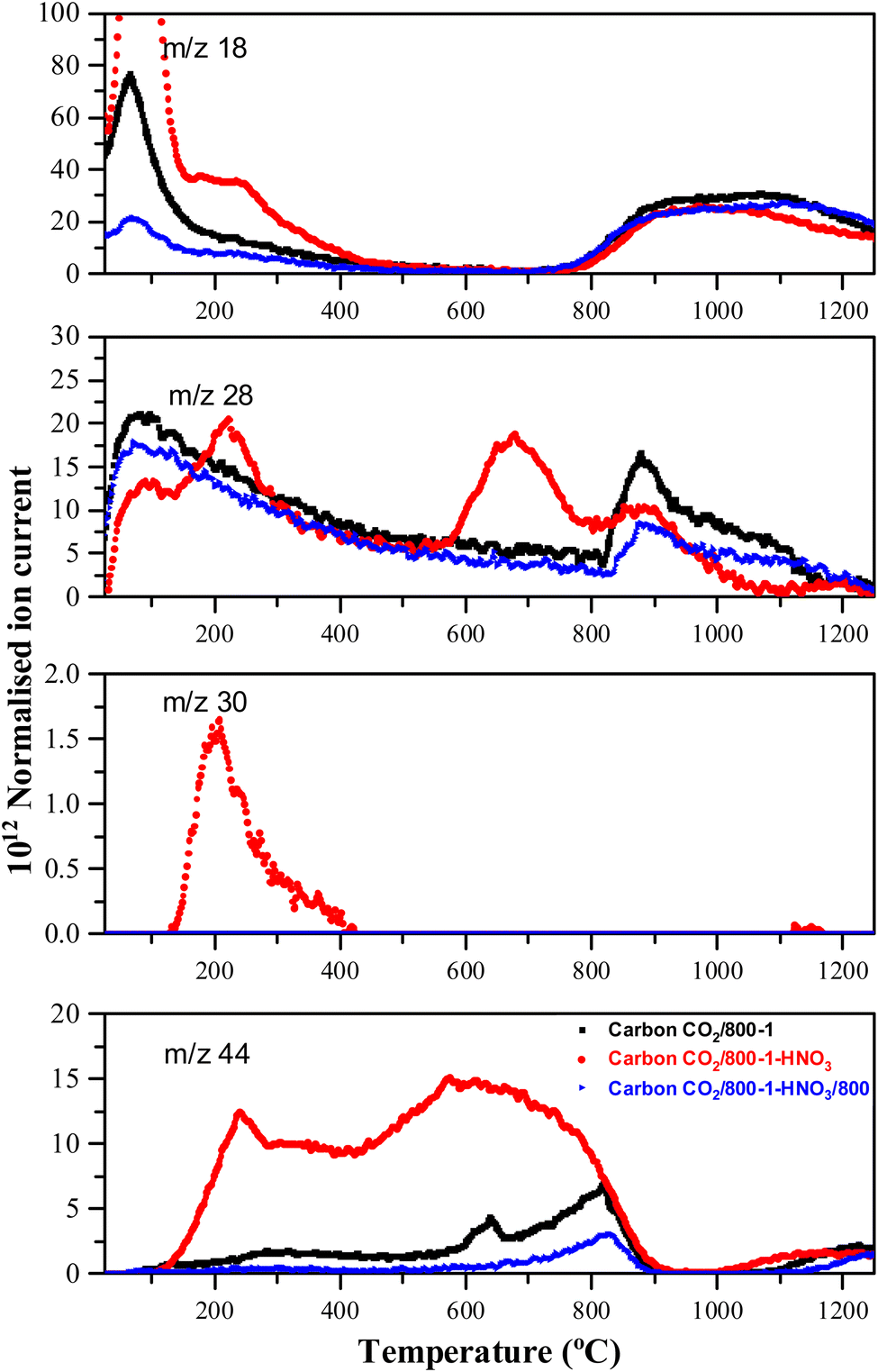
Carbons CO2/800-1 and N2/800-1 were used as precursors for treatment to incorporate functional groups into the carbon structure. HNO3 treatment of carbon CO2/800-1 mainly incorporates oxygen functional groups into the carbon structure. The total surface oxygen of carbon CO2/800-1 increased from 8.1 at% to 13.54 at% for CO2/800-1-HNO3 (see Table 3). In comparison, elemental analysis of the bulk samples gave 7.54 wt% for CO2/800-1 and 23.84 wt% in CO2/800-1-HNO3 (see Table 1). The XPS C 1s and O 1s spectra of carbons CO2/800-1 and CO2/800-1-HNO3 are compared in Fig. 1a and b. Comparison of the C 1s spectra shows that the functional group distribution has a marked increase in the O–CO peak at ∼288.8 eV from ∼15.4% in carbon CO2/800-1 to 44.5 ± 0.3% in carbon CO2/800-1-HNO3 and a marked decrease in the CO peak at 287.9 eV from 24.5% to <0.1% (Table S4 and S5, ESI†). The C–O peak at 286.5 eV only decreased slightly in intensity for 60 to 55.5% of the distribution. These changes are consistent with the incorporation of carboxylic groups. Furthermore, the O 1s spectra showed that HNO3 treatment resulted in the O–C (ether and hydroxyl groups bonded to aromatics) peak at 533.3 eV increased from 28.2% (2.3 at%) in carbon CO2/800-1 to 46.93 ± 0.45% (6.4 at%) in carbon CO2/800-1-HNO3, while C–O aliphatic peak at 532.2 eV decreased from 35.69 (2.96 at%) to 13.3 ± 0.66% (1.80 at%) (Table S5b, ESI†). The corresponding CO peak distribution only increased slightly in carbon CO2/800-1-HNO3, but since the surface oxygen content is much higher in carbon CO2/800-1-HNO3, the CO peak corresponded to 4.5 at% compared with 2.5 at% in carbon CO2/800-1. The XPS results show increases in carboxylic, anhydride, and lactone groups.
 | ||
| Fig. 1 Comparison of XPS spectra, curve fitting, and residuals of carbons (a) C 1s, carbon CO2/800-1 (b) C 1s, carbon CO2/800-1-HNO3, (c) O 1s, carbon CO2/800-1, (d) O 1s, carbon CO2/800-1-HNO3, (e) O 1s, carbon CO2/800-1-HNO3/400 and (f) O 1s, carbon CO2/800-1-HNO3/800 and (g) N 1s, carbon CO2/800-1-HNO3,. | ||
Heat treatment of carbon CO2/800-1-HNO3 decreased the surface oxygen content from 13.54 at% for carbon CO2/800-1-HNO3 to 8.4 at% for carbon CO2/800-1-HNO3/400, and to 2.85 at% for CO2/800-1-HNO3/800 (Table 3). The XPS survey scan showed that metal species were absent (see Table 3). Therefore, possible O 1s peaks from residual inorganic species do not contribute to the O 1s spectra. The C 1s spectra showed that heat treatment of carbon CO2/800-1-HNO3 to 800 °C to form carbon CO2/800-1-HNO3/800 increased the C–O/C–OH peak distribution from 55.5% to 93% of the oxygen functionality and decreased the O–CO peak from 44.5% to 6.7%. These results are consistent with the decomposition of carboxylic groups and the formation of C–O/OH during heat treatment. The O 1s spectra showed that heat treatment of carbon CO2/800-1-HNO3 decreased the CO peak at 531.5 eV and the larger peak in the O–C attached to aromatic groups at 533.3 eV and a marked increase in the C–O bonded to aliphatic carbon at 532.2 eV. This change in the distribution of XPS peaks is consistent with the decomposition of carboxylic and the formation of phenolic and ether groups. The O 1s spectra for this series show evidence for the component peaks as shoulders (Fig. 1d–f), thereby supporting the curve resolution scheme. Thermally labile carboxylic groups in CO2/800-1-HNO3 are also confirmed by the loss of CO2 in TPD, as discussed later.
HNO3 oxidation results in the incorporation of small amounts of thermally labile nitrogen species (0.8 at%) into the carbon structure (Fig. 1g) that decomposes on heat treatment (Fig. S27 and S28, ESI†). The XPS N 1s spectrum for carbon CO2/800-1-HNO3 was curve-fitted, revealing peaks at 399.9, 401.9, and 405.8 eV. The most prominent XPS peak (47.1 ± 0.7%) at 405.8 eV was tentatively assigned to N-oxide.63,64 The other N 1s peaks were at 399.9 eV (33.2%) assigned to pyrrolic or N sp3 nitrogen and 401.9 eV (19.7 ± 0.8%) assigned to quaternary nitrogen, but there was no evidence for significant amounts of pyridinic nitrogen. The TPD supports the N-oxide assignment, which showed NO desorption at HTT <400 °C (see TPD section). The N 1s peak at 398.5 eV (21.5%) in carbon CO2/800-1-HNO3/400 was assigned to N sp2 (pyridinic groups). The peak at 399.5 eV (49.5%) and 400.6 eV (21.1%) were assigned to pyrrolic, with the peak at 402.3 eV (8%) to quaternary nitrogen by analogy with high-temperature carbons, but other labile nitrogen species could also contribute to the peaks. The decomposition of thermally labile surface groups was evident from the absence of the 405.8 eV N-oxide peak in the XPS N 1s spectrum of CO2/800-1-HNO3/400 (Fig. S27b, ESI†) and the absence of nitrogen surface species in the N 1s XPS spectra of CO2/800-1-HNO3/800 (Fig. S27c, ESI†).
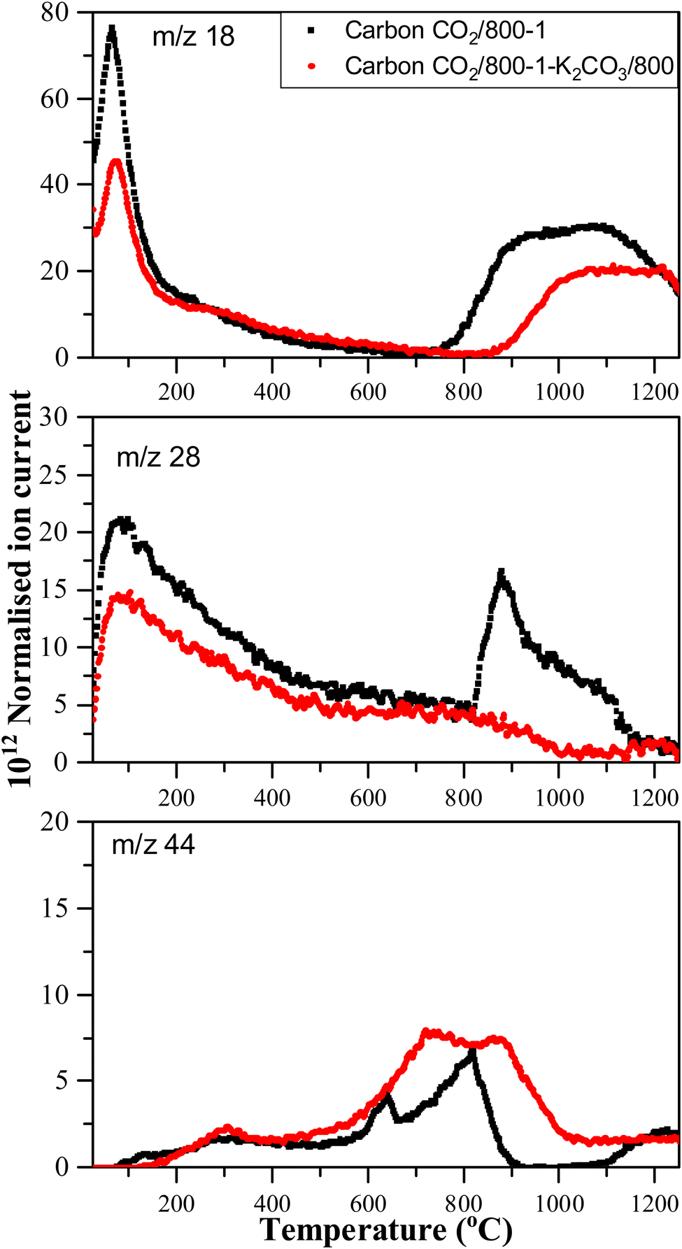
Treatment of carbon CO2/800-1 with K2CO3 at 800 °C resulted in a small decrease in surface oxygen content from 8.3 to 7.1 at%. The XPS survey scan showed that metal species and residual K2CO3 were absent (see Table 3). A comparison of the XPS C 1s spectra does not show any apparent changes in the distribution of oxygen surface species. However, the O 1s spectrum showed a decrease in the CO peak at ∼531 eV from 30.6% in carbon CO2/800-1 to 11.7% in carbon CO2/800-1-K2CO3/800. This change was accompanied by smaller increases in the intensities of C-O/C-OH bonded to aliphatic (532.2 eV) and O–C/OH bonded to aromatics (533.5 eV) (Fig. 1c and 2, and Table S5b, ESI†). The titration results showed increased acidic character in aqueous solution, attributed to increased phenolic and carboxylic groups. The TPD results show that more thermally labile oxygen groups in the carbon structure gave CO2 evolution starting at ∼550 °C.
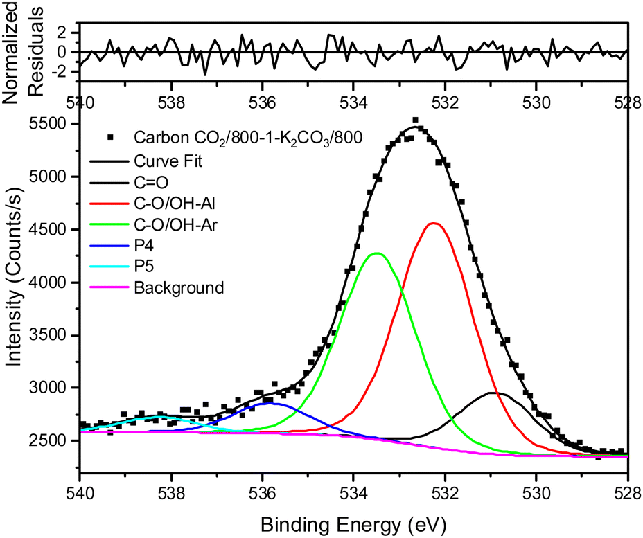 | ||
| Fig. 2 XPS O 1s spectrum, curve fitting, and residuals of carbon CO2/800-1-K2CO3/800. | ||
The XPS spectrum of carbon N2/800-1 shows that surface nitrogen species are minimal (see Fig. S28b and Table 3, ESI†) and the O 1s and N 1s spectra for N2/800-1-NH3/600 and N2/800-1-NH3/800 are shown in Fig. 3. NH3 treatment of carbon N2/800-1 increased surface nitrogen content to 2.56 at% in carbon N2/800-1-NH3/600 and 4.86 at% in carbon N2/800-1-NH3/800. NH3 treatment also reduced the surface oxygen content from 8.1 at% for the precursor (carbon N2/800-1) to 2.7 for N2/800-1-NH3/600 and 1.8 at% N2/800-1-NH3/800 (Table 3). The nitrogen content obtained by chemical analysis of N2/800-1-NH3/800 was similar (4.76 wt%) to the XPS surface concentration (4.86 at%). However, the surface oxygen content was 1.8 at%, which is much lower than 10.39 wt% oxygen from chemical analysis, indicating differences between the surface and bulk of the sample. Titration studies discussed later indicated that carbon N2/800-1-NH3/800 had some weakly acidic groups.
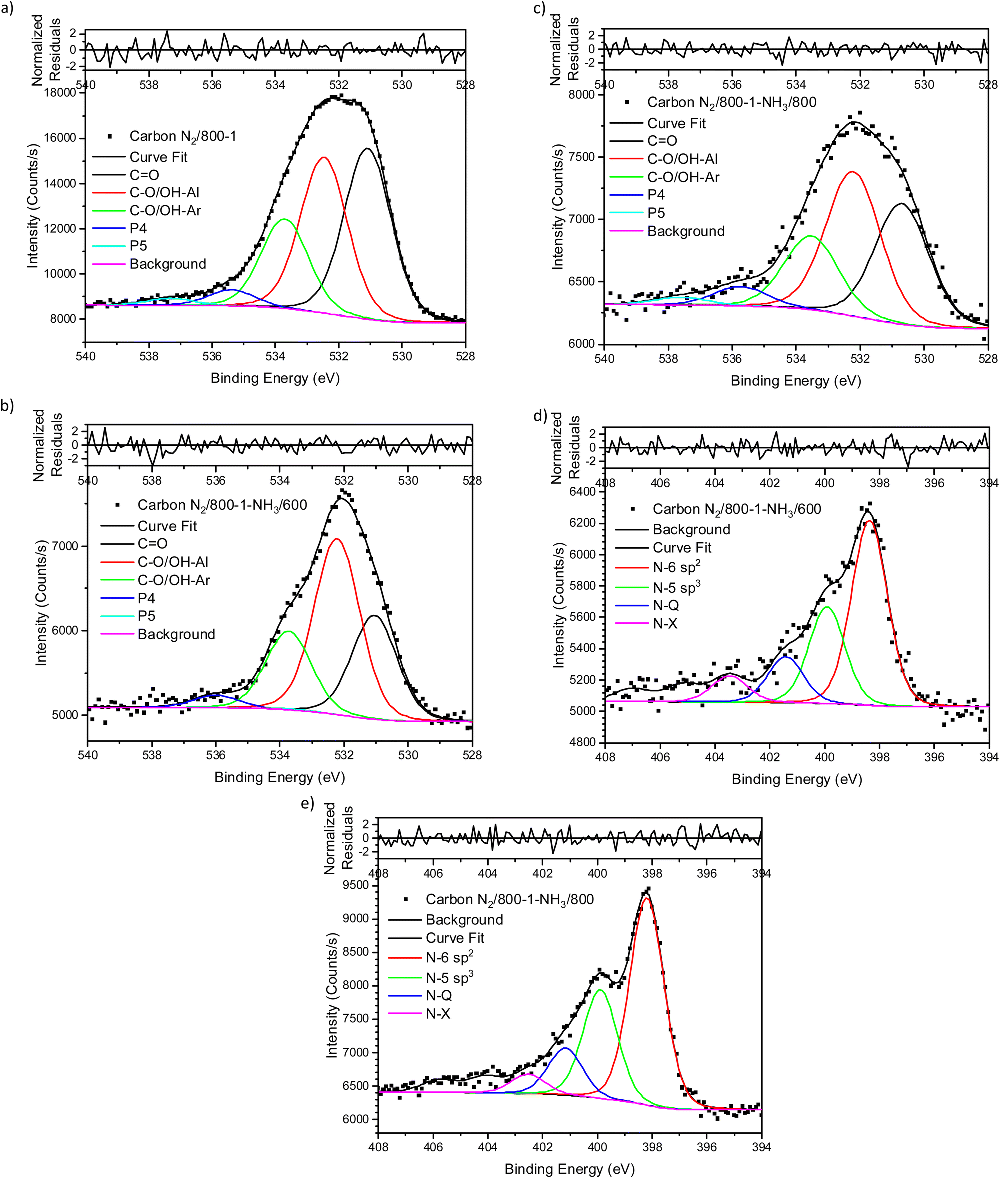 | ||
| Fig. 3 Comparison of XPS spectra, curve fitting, and residuals of untreated carbon and NH3 treated carbons (a) O 1s, carbon N2/800-1, (b) O 1s, carbon N2/800-1-NH3/600 (c) O 1s, carbon N2/800-1-NH3/800, (d) N 1s, carbon N2/800-1-NH3/600 and (e) N 1s, carbon N2/800-1-NH3/800. | ||
 | ||
| Fig. 4 Comparison of TPD profiles of carbon CO2/800-1 and HNO3 oxidized and heat-treated carbons (CO2/800-1-HNO3 and CO2/800-1-HNO3/800) in He (35 mL min−1) at 10 °C min−1. | ||
 | ||
| Fig. 5 Comparison of TPD profiles of carbons CO2/800-1 and CO2/800-1-K2CO3/800 in He (35 mL min−1) at 10 °C min−1. | ||
Curve fitting was used to analyze the C 1s, O 1s, and N 1s XPS spectra. The C 1s spectra showed that the distribution of oxygen surface groups was not changed very much by NH3 treatment at 600 and 800 °C (Table S5a, ESI†). However, the XPS O 1s spectra showed that NH3 treatment changed the distribution of surface oxygen species, as shown by the relative intensities of the CO (531 eV) and C–O attached to aliphatic (532.2 eV) peaks (Table 4). The XPS N 1s showed that pyridinic and pyrrolic groups were the two primary forms of nitrogen, and the N-6/N-5 ratios (∼2:1) were similar for both carbons (Table 5). Previous studies of the high-pressure carbonization of pure organic compounds with well-defined pyridinic and pyrrolic nitrogen groups as a function of HTT have shown63 that the order of stability of surface groups is as follows:
| quaternary > pyridinic > pyrrolic |
| Carbon sample | Components from O 1s profiles obtained from curve resolution | ||||
|---|---|---|---|---|---|
| Peak 1 | Peak 2 | Peak 3 | Peak 4 | Peak 5 | |
| 531.12 ± 0.23 eV | 532.27 ± 0.11 eV | 533.53 ± 0.15 eV | 535.49 ± 0.31 eV | 537.49 ± 0.58 eV | |
| CO carbonyl carboxylic |
C–O/OH-aliphatic | CO/OH-aromatic | Chemisorbed H2O/O2 | π–π* | |
| N2/600-1 | 2.29 | 3.35 | 3.10 | 0.26 | 0.12 |
| N2/600-3 | 2.23 | 3.54 | 3.05 | 0.24 | 0.12 |
| N2/700-1 | 2.98 | 3.13 | 1.80 | 0.26 | 0.06 |
| N2/800-1 | 3.10 | 2.78 | 1.83 | 0.28 | 0.11 |
| N2/800-3 | 2.74 | 3.16 | 2.03 | 0.30 | 0.12 |
| N2/1000-1 | 2.64 | 3.20 | 2.17 | 0.30 | 0.11 |
| CO2/700-1 | 2.46 | 3.03 | 2.46 | 0.28 | 0.15 |
| CO2/700-3 | 2.50 | 2.27 | 1.66 | 0.32 | 0.12 |
| CO2/800-1 | 2.54 | 2.96 | 2.34 | 0.34 | 0.12 |
| CO2/800-3 | 2.28 | 2.76 | 2.25 | 0.28 | 0.13 |
| CO2/1000-1 | 3.25 | 3.26 | 2.08 | 0.29 | 0.08 |
| CO2/800-1-K2CO3/800 | 0.83 | 3.09 | 2.56 | 0.40 | 0.19 |
| CO2/800-1-HNO3 | 4.54 | 1.80 | 6.35 | 0.60 | 0.24 |
| CO2/800-1-HNO3/400 | 2.52 | 1.58 | 3.67 | 0.42 | 0.22 |
| CO2/800-1-HNO3/800 | 0.38 | 1.60 | 0.68 | 0.12 | 0.07 |
| N2/800-1-NH3/600 | 0.77 | 1.30 | 0.60 | 0.09 | 0.00 |
| N2/800-1-NH3/800 | 0.58 | 0.69 | 0.35 | 0.09 | 0.04 |
| Carbon sample | Content of each N component | ||||||
|---|---|---|---|---|---|---|---|
| N-6/N sp2 pyridinic | N-5/N sp3 pyrrolic | N-5/N sp3 pyrrolic | N–Q | N–X | N-Oxide | Total N content | |
| Curve fitting peaks for samples N2/800-1-NH3/600 and N2/800-1-NH3/800 gave several very weak peaks in the binding energy range 402–407 eV with inconsistent binding energies and amounting to ∼12–15% of the total peak area. | |||||||
| Energy (eV) | 398.3 | 399.9 | 401.2 | ||||
| N2/800-1-NH3/600 (at%) | 1.24 | 0.65 | 0.31 | 0.37 | 2.56 | ||
| N2/800-1-NH3/800 (at%) | 2.41 | 1.30 | 0.56 | 0.60 | 4.86 | ||
| Energy (eV) | 399.9 | 401.9 | 405.8 | ||||
| CO2/800-1-HNO3 (at%) | 0.26 | 0.15 | 0.36 | 0.77 | |||
| Energy (eV) | 398.6 | 399.6 | 400.6 | 402.3 | |||
| CO2/800-1-HNO3/400 (at%) | 0.29 | 0.66 | 0.28 | 0.11 | — | — | 1.33 |
NH3 treatment of carbon N2/800-1 incorporated mainly pyridinic groups with smaller amounts of pyrrolic and quaternary nitrogen, changing the surface chemistry and influencing electrochemistry.
The titration results in Table 6 showed similar trends to those observed previously for coconut-derived carbons, HNO3 oxidized carbon, and heat treatment studies of HNO3 oxidized carbons under a nitrogen atmosphere up to 800 °C.33,34 The inorganic contents of Series 1 and 2 carbons are low (1.5–3.9 wt%), and the functionalized carbons were much lower (∼0.5 wt%). Therefore, the inorganic material only makes a minimal contribution to the basic characteristics of the carbons. The acid and base titration results for carbons CO2/800-1 and CO2/800-1-HNO3 showed that HNO3 oxidation incorporated carboxylic, lactone/lactol, and phenolic groups into the carbon structure, which was consistent with both the O 1s and C 1s XPS data. In addition, a small amount of nitrogen (0.8 at%) was also incorporated into the carbon CO2/800-1-HNO3 structure. The XPS spectrum shows that N-oxide and pyrrolic functionalities are the primary forms of nitrogen in oxidized carbon CO2/800-1-HNO3. Titration results showed that carbons CO2/800-1, N2/800-1, and N2/1000-1 were basic carbons. CO2/700-1 contained small quantities of phenolic, lactone/lactol groups, carboxylic groups, and some basic groups. The titration results of CO2/800-1-K2CO3/800 showed that K2CO3 treatment of carbon CO2/800-1 at 800 °C also introduced a range of carboxyl, phenolic, and lactone/lactol functional groups and increased the acidity compared to CO2/800-1. These results are consistent with the XPS and TPD results discussed later. Titration studies show that N2/800-1-NH3/800 shows some weakly acidic character and basic character, whereas carbon N2/800-1 only has basic character. However, the surface oxygen was decreased by NH3 treatment at 800 °C to 1.8 at% (Table 3).
| Carbon sample | Phenolic | Lactone/lactol | Carboxylic | Basic |
|---|---|---|---|---|
| CO2/700-1 | 0.210 | 0.065 | 0.036 | 0.427 |
| CO2/800-1 | 0.029 | 0 | 0 | 0.618 |
| CO2/1000-1 | 0 | 0 | 0 | 0.453 |
| N2/600-1 | 0.024 | 0 | 0 | 0.317 |
| N2/800-1 | 0 | 0 | 0 | 0.506 |
| N2/1000-1 | 0 | 0 | 0 | 0.228 |
| CO2/800-1-HNO3 | 0.062 | 0.348 | 0.912 | 0.037 |
| CO2/800-1-HNO3/400 | 0.915 | 0.017 | 0.206 | 0 |
| CO2/800-1-HNO3/800 | 0.494 | 0 | 0 | 0 |
| CO2/800-1-K2CO3/800 | 0.296 | 0.048 | 0.166 | 0.253 |
| N2/800-1-NH3/800 | 0.287 | 0 | 0 | 0.541 |
The TPD profiles for CO, CO2, and H2O for carbons in He (Series 1) and CO2 (Series 2) carbonization atmospheres are shown in Fig. S29 (ESI†). The low-temperature regions (<150 °C) of the TPD profiles show the desorption of H2O and N2 physisorbed in the porous structures with peaks at ∼80 °C. Physisorbed O2 was also desorbed, but this is not shown. The higher temperature peaks are due to the decomposition of functional groups. The TPD profiles for Series 1 of H2O, CO, and CO2 carbon decomposition products shift to higher temperatures with increasing HTT (Fig. S29a, ESI†). Carbon N2/600-1 has a significant weight loss of 4.35 wt% on heat treatment from 600 to 800 °C but much lower weight losses of 1.57 wt% between 800 and 1000 °C and 0.72 wt% between 1000 and 1200 °C (Fig. S30, ESI†). The TPD profiles of H2O, CO, and CO2 decomposition products for Series 2 carbons also shift to higher temperatures with increasing carbon HTT (Fig. S29b, ESI†). Carbon CO2/700-1 loses 2.32 wt% on heating from 700 to 800 °C in TPD but smaller weight loss values of 1.95 and 0.69 wt% over the temperature ranges 800–1000 °C and 1000–1200 °C, respectively. The weight loss during the carbonization process occurs above the corresponding HTT for the carbon (Fig. S29, ESI†), leading to changes in the bulk carbon structure.
HNO3 treatment of carbon CO2/800-1 incorporated additional oxygen and nitrogen functionality into the carbon structure to form oxidized carbon CO2/800-1-HNO3. The TPD CO2 profile of carbon CO2/800-1-HNO3 had a wide temperature range of (150–900 °C) with broad and overlapping desorption peaks (Fig. 4). The low temperature CO2 TPD peak at ∼239 °C overlapped with peaks at ∼231 °C for m/z 18 (H2O), at ∼207 °C for m/z 30 (NO) and ∼221 °C for m/z 28 (CO/N2). The desorption of H2O and NO are consistent with the decomposition of carboxylic acid and N-oxide surface groups, respectively. The low-temperature decomposition of N-oxides was reported previously by Xiao et al.35 The XPS results show that N-oxide functional groups (Fig. 1g and Table 5) were decomposed by heat treatment to 400 °C, but pyrrolic groups were still present (carbon CO2/800-1-HNO3/400, Fig. S27b, ESI†). Further heat treatment to 800 °C showed that all nitrogen surface groups were absent (carbon CO2/800-1-HNO3/800, Fig. S27c, ESI†). The other broad overlapping CO2 peaks are due to the desorption of carboxylic anhydride, lactone, and carbonyl surface sites, but H2O desorption is minimal over the temperature range 450–780 °C with a multicomponent peak in the temperature range (780–1250 °C), which is assigned to the decomposition of phenolic groups and surface reactions. The m/z 28 (CO) desorption peaks were observed at 675 and 878 °C, which are attributed to anhydride, lactones, etc. Heat treatment of oxidized carbon CO2/800-1-HNO3 to 800 °C removed oxygen functional groups, which decompose below 800 °C, forming carbon CO2/800-1-HNO3/800 (see XPS data in Table 4). The TPD profile of carbon CO2/800-1-HNO3/800 was comparable to carbon CO2/800-1, thereby showing the effect of HTT (Fig. 4). Previous thermolysis studies of HNO3 oxidized carbons showed that the order of thermal stability was:
| carboxylic acid < lactone/lactol < phenolic, carbonyl, semiquinone < chromene/pyrone |
Comparison of the TPD profiles of carbons CO2/800-1-K2CO3/800 and CO2/800-1 shows that the reaction has modified the profiles (Fig. 5). Carbon CO2/800-1-K2CO3/800 showed a shift of the m/z 18 water peak to a higher temperature, and the m/z 28 CO peak was negligible. The K2CO3 treatment procedure produced strong bimodal CO2 desorption peaks at 725 and 875 °C. The low-temperature CO2 peak was attributed to lactones/carboxyl, while the high-temperature CO2 peak, which coincides with the start of H2O evolution, was assigned to the decomposition of phenolic and lactol groups and the reaction of surface species. The O 1s XPS results indicate carbon CO2/800-1-K2CO3/800 has lower CO contents than CO2/800-1 (Table 4 and Table S5, ESI†). The titration results for carbons CO2/800-1-K2CO3/800 show increases in acidic carbon–oxygen surface groups compared with carbon CO2/800-1 with surface groups in the order: phenolic > carboxyl > lactone/lactol. The TPD results are consistent with the XPS (Table 4) and titration results (Table 6).
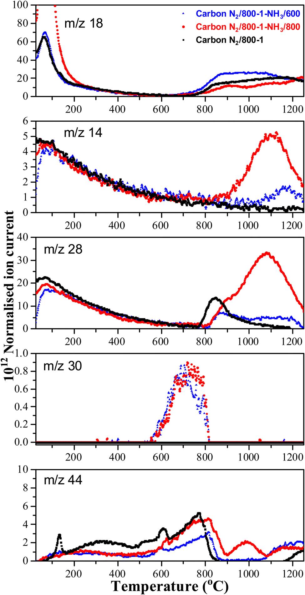
High-temperature ammonia treatment of carbons led to the incorporation of nitrogen functional groups into the carbon structure. The TPD m/z 28 (CO) peak profile for the starting carbon material N2/800-1 did not have a corresponding peak for m/z 14 (Fig. 6). Chemical analysis and the XPS spectrum of carbon N2/800-1 show minimal bulk and surface nitrogen contents. Therefore, the comparison of m/z 14 and m/z 28 TPD profiles allows the desorption of N2 to be distinguished from CO for carbons N2/800-1-NH3/600 and N2/800-1-NH3/800. The TPD profiles of both these samples had weak m/z 28 desorption peaks at ∼850–900 °C. The m/z 14 and 28 gas evolution profiles show N2 desorption and some CO desorption from 850–1200 °C (Fig. 6). N2 is the major nitrogen-containing desorption product. Nitrogen surface functional groups in carbon are mobile, reacting on the surface to form N2.35 Both NH3 treated carbons N2/800-1-NH3/600 and N2/800-1-NH3/800 showed small TPD peaks for m/z 30 (NO) at ∼740 °C (Fig. 6). The thermolysis of nitrogen functional groups shows that pyridine N-oxide is the least stable. Pyrrolic-N gradually transforms into pyridinic-N and subsequently into quaternary-N with increasing HTT.35,63 These nitrogen-containing desorption products are consistent with the nitrogen species detected in XPS (Fig. 1g and 3, Fig. S27 and Table 5, Table S5, ESI†) discussed previously.
 | ||
| Fig. 6 Comparison TPD profiles of carbon N2/800-1 and NH3 treated carbons N2/800-1-NH3/600 and N2/800-1-NH3/800 in He (35 mL min−1) at 10 °C min−1. | ||
C and CO stretching vibrations. The ATR spectra for Series 1 carbons N2/600-1 and N2/800-1 show that the intensity of the band at 1579 cm−1 decreases markedly at 800 °C (Fig. S41a, ESI†). However, the infrared spectrum of carbon CO2/800-1 in Series 2 has a more substantial band at 1580 cm−1 than carbon N2/800-1, indicating that carbonization in a CO2 atmosphere has incorporated some surface oxygen groups into the carbon structure (see Fig. S41b, ESI†). Comparison of the ATR spectra of carbons CO2/800-1 and CO2/800-1-K2CO3/800 shows that the spectra are very similar, but the latter have higher intensity (see Fig. S41c, ESI†). The main ATR peaks at 1580 and 1713 cm−1 for CO2/800-1-HNO3, as shown in Fig. S41d (ESI†), are similar to the diffuse reflectance spectrum reported for nitric acid oxidation of a steam-activated carbon, which had bands at 1576 and 1717 cm−1.35 The analytical data for carbon CO2/800-1-HNO3 is similar to that reported for nitric acid oxidation of a steam-activated carbon.35 The peak at 1713 cm−1 is consistent with the presence of carboxylic groups. Heat treatment studies for HNO3 oxidation of the steam-activated carbon resulted in progressive decomposition of the surface oxygen groups, with lactone and lactol groups forming at 400–600 °C. The spectra for the carbon treated at high temperatures with ammonia are shown in Fig. S41e (ESI†). There are relatively small differences between the infrared spectra of carbons N2/800-1 and N2/800-1-NH3/600. However, the infrared spectrum of carbon N2/800-1-NH3/800 is markedly different with the loss of the 1007 cm−1 peak and increased intensity for the 1190 and 1577 cm−1 peaks.
3.4. Carbonaceous molecular structure
| Carbon sample | I D/IG | A D/AG | FWHMD (cm−1) | FWHMG (cm−1) | D-peak (cm−1) | G-peak (cm−1) | Reduced χ2 | R 2 (COD) |
|---|---|---|---|---|---|---|---|---|
| a Average values. | ||||||||
| Carbonization under N2 (Series 1) | ||||||||
| N2/600-0 | 0.65 | 1.22 | 182.9 | 66.3 | 1345.4 | 1594.7 | 374.6 | 0.992 |
| N2/600-1 | 0.67 | 1.26 | 181.6 | 64.9 | 1344.6 | 1595.3 | 212.8 | 0.993 |
| N2/600-3 | 0.70 | 1.31 | 178.2 | 64.7 | 1341.6 | 1596.7 | 168.1 | 0.992 |
| N2/700-0a | 0.81 | 1.47 | 164.2 | 61.7 | 1337.5 | 1597.5 | 61.3, 87.2 | 0.993, 0.990 |
| N2/700-1a | 0.85 | 1.54 | 162.8 | 61.1 | 1336.3 | 1598.2 | 54.5, 66.0 | 0.990, 0.992 |
| N2/700-3a | 0.92 | 1.57 | 160.9 | 63.6 | 1337.4 | 1596.9 | 52.9, 63.0 | 0.985, 0.992 |
| N2/800-0a | 0.99 | 1.71 | 153.1 | 60.1 | 1337.5 | 1598.6 | 46.8, 60.5 | 0.976, 0.991 |
| N2/800-1a | 0.98 | 1.67 | 157.2 | 62.8 | 1338.5 | 1598.3 | 28.7, 34.8 | 0.992, 0.977 |
| N2/800-3a | 1.02 | 1.65 | 154.6 | 64.5 | 1340.1 | 1600.0 | 37.5, 43.8 | 0.987–0.991 |
| N2/1000-0 | 1.06 | 1.74 | 150.0 | 61.8 | 1338.1 | 1595.3 | 99.0 | 0.996 |
| N2/1000-1 | 1.14 | 1.70 | 142.3 | 64.2 | 1341.0 | 1596.1 | 104.3 | 0.993 |
| N2/1000-3 | 1.16 | 1.67 | 137.7 | 64.8 | 1342.2 | 1595.7 | 99.2 | 0.992 |
| Carbonization under CO2 (Series 2) | ||||||||
| CO2/700-0 | 0.85 | 1.50 | 164.6 | 63.0 | 1336.2 | 1595.0 | 68.3 | 0.994 |
| CO2/700-1a | 0.90 | 1.54 | 161.3 | 63.8 | 1337.3 | 1597.0 | 41.3–50.4 | 0.991–0.992 |
| CO2/700-3a | 0.95 | 1.62 | 158.6 | 62.8 | 1336.5 | 1596.3 | 39.2–55.0 | 0.987–0.993 |
| CO2/800-0 | 0.96 | 1.58 | 154.2 | 63.8 | 1337.7 | 1597.4 | 54.8 | 0.993 |
| CO2/800-1a | 1.00 | 1.68 | 153.4 | 62.0 | 1337.8 | 1597.4 | 35.2–40.7 | 0.985–0.992 |
| CO2/800-3a | 1.05 | 1.72 | 142.3 | 58.9 | 1336.9 | 1597.3 | 38.6, 53.4 | 0.985–0.990 |
| CO2/1000-0 | 1.06 | 1.74 | 145.2 | 59.9 | 1336.8 | 1597.0 | 33.6 | 0.989 |
| CO2/1000-1 | 1.11 | 1.73 | 144.0 | 63.0 | 1340.4 | 1596.0 | 117.1 | 0.994 |
| Functionalized carbons | ||||||||
| CO2/800-1-HNO3 | 0.96 | 1.43 | 141.7 | 64.5 | 1344.2 | 1601.9 | 64.9 | 0.994 |
| CO2/800-1-HNO3/400 | 0.94 | 1.47 | 150.7 | 65.5 | 1343.7 | 1601.0 | 45.5 | 0.993 |
| CO2/800-1-HNO3/800 | 1.04 | 1.80 | 133.5 | 52.3 | 1343.1 | 1605.3 | 94.4 | 0.985 |
| CO2/800-1-K2CO3/800 | 1.08 | 1.68 | 139.4 | 60.9 | 1341.4 | 1602.0 | 46.7 | 0.986 |
| N2/800-1-NH3/600 | 1.02 | 1.92 | 153.6 | 55.3 | 1337.8 | 1598.3 | 138.3 | 0.996 |
| N2/800-1-NH3/800 | 1.06 | 1.83 | 145.8 | 57.1 | 1339.2 | 1602.1 | 234.6 | 0.994 |
The ID/IG ratio (peak intensity ratio of the D and G peaks) is used widely as a measure of the degree of ordered carbon in carbon materials, while the peak area ratio for the D and G peaks (AD/AG) are less commonly reported.77,78 The Raman spectra for carbons prepared in N2 (Series 1) and CO2 (Series 2) atmospheres show markedly increased ID/IG and AD/AG ratios with increasing HTT from 600 °C up to 800 °C and slower increase from 800 °C to 1000 °C (Fig. S40a and b, ESI†). Previous studies of the Raman spectra of carbons derived from a wide range of biomass materials have shown that ID/IG increases for the temperature range 800 to ∼2000 °C but decreases at higher temperatures.79 In contrast, changes with carbonization hold time were small, indicating that temperature is the primary experimental carbonization parameter influencing carbon structure. The full width at half maximum of the D peak (FWHMD) decreased gradually with increasing HTT (Fig. S40c, ESI†), and this carbon structural rearrangement resulted in a more ordered carbon structure.80 The full width at half maximum intensity of the G peak (FWHMG), D, and G peak positions are included in Table 7, but none of these parameters show marked changes with carbonization hold time (0–3 h) or carbonization gaseous atmosphere. The changes in D and G peak Raman shifts with HTT were small. Therefore, significant conclusions regarding carbon structure could not be obtained from these parameters.81
The incorporation of functional groups produced minor changes in the Raman spectra. HNO3 oxidation reduced the FWHMD of the D band, ID/IG, and AD/AG ratio in the Raman spectra of carbon CO2/800-1-HNO3 compared with carbon CO2/800-1. Heat treatment of carbon CO2/800-1-HNO3 resulted in substantial weight loss (Fig. S30b, ESI†) due to the decomposition of the functional groups in TPD (Fig. 4). The AD/AG ratio in the Raman spectrum of carbon CO2/800-1-HNO3/800 was very similar to that of the starting material carbon CO2/800-1. The values of D bandwidth (FWHMD) were slightly lower for the heat-treated carbon series CO2/800-1-HNO3, CO2/800-1-HNO3/400, and CO2/800-1-HNO3/800 than for the initial carbon CO2/800-1. The high-temperature treatment of carbon CO2/800-1 with K2CO3 at 800 °C and treatment of carbon N2/800-1 with NH3 at 800 °C reduced FWHMD slightly compared to the corresponding precursor materials. The changes in the Raman D/G peak intensity ratios, peak area ratios, and D bandwidths show that carbonization temperature has a much more significant effect on the carbon structure than the chemical treatment and thermolysis to incorporate functional groups.
| Carbon sample | Crystallite thickness, Lc (Å) | Interlayer distance, d002, (Å) | Crystallite diameter, La (Å) |
|---|---|---|---|
| a Average values. | |||
| Carbonization in N2 (Series 1) | |||
| N2/600-1 | 10.75 | 4.14 | 18.33 |
| N2/600-3 | 10.67 | 3.99 | 18.61 |
| N2/700-0 | 9.83 | 3.83 | 19.29 |
| N2/700-1 | 10.19 | 4.01 | 21.10 |
| N2/700-3 | 9.98 | 3.85 | 21.00 |
| N2/800-0 | 10.02 | 3.83 | 20.09 |
| N2/800-1 | 10.21 | 3.86 | 21.03 |
| N2/800-3a | 9.98 | 3.83 | 23.57 |
| N2/1000-1 | 9.99 | 3.86 | 26.85 |
| N2/1000-3 | 10.12 | 3.84 | 28.6 |
| Carbonization in CO2 (Series 2) | |||
| CO2/700-1 | 9.54 | 3.90 | 19.98 |
| CO2/800-0 | 9.79 | 3.86 | 23.52 |
| CO2/800-1a | 10.14 | 3.86 | 23.53 |
| CO2/800-3a | 9.32 | 3.86 | 24.31 |
| CO2/1000-1 | 10.23 | 4.04 | 28.71 |
| Functionalized carbons | |||
| CO2/800-1-HNO3 | 10.07 | 3.92 | 25.65 |
| CO2/800-1-HNO3/400 | 10.32 | 3.66 | 25.98 |
| CO2/800-1-HNO3/800 | 10.81 | 3.80 | 24.01 |
| CO2/800-1-K2CO3/800 | 8.55 | 4.12 | 27.87 |
| N2/800-1-NH3/600 | 10.07 | 4.18 | 23.00 |
| N2/800-1-NH3/800 | 10.24 | 3.76 | 26.99 |
Carbons with the same HTT (CO2/800-1 and N2/800-1) were used for the carbon functionalization studies with maximum treatment temperatures of 800 °C to eliminate structural changes due to HTT. Carbon molecular structure changes during functionalization studies were investigated by comparison of X-ray diffraction parameters d002, Lc, and La (see Table 8). The nitric acid oxidation of carbon CO2/800-1 produced carbon CO2/800-1-HNO3, and Lc, d002, and La were increased, but the values of Lc and d002 were close to three standard deviations. HNO3 oxidation of carbon CO2/800-1 increased the crystallite size (La) from 23.53 Å for carbon CO2/800-1 to 25.65 Å in carbon CO2/800-1-HNO3. This is consistent with the dewrinkling of the graphene layers. Heat treatment studies of carbon CO2/800-HNO3 to form CO2/800-1-HNO3/800 led to a reduction in La to 24.01 Å, similar to the starting carbon material.
Treatment of carbon CO2/800-1 with K2CO3 at 800 °C decreased Lc and increased d002 and La (see Table 8). The apparent crystallite size (La) increased from 23.53 Å for carbon CO2/800-1 to 27.87 Å for carbon CO2/800-1-K2CO3/800. The increase in the apparent crystallite size results from the dewrinkling of the graphene layers. Treatment of carbon N2/800-1 with NH3 at 800 °C to form carbon N2/800-1-NH3/800 did not change Lc, d002 was decreased, and La increased. The apparent crystallite size increased from 21.03 Å for carbon N2/800-1 to 26.99 Å for carbon N2/800-1-NH3/800. This is also consistent with the dewrinkling of the graphene layers. Therefore, all three treatment procedures increased apparent crystallite size (La). Heat treatment of carbon CO2/800-1-HNO3 increased Lc and decreased La, while there was no clear trend in d002.
Many carbons, including various graphite, glassy carbons, fibers, carbon black, and other carbons, have been used as electrode materials.7 The carbons used in this study were non-graphitizable biochars and have the following PXRD parameter ranges: crystal thickness (Lc) 8.55–10.75 Å, apparent crystallite diameter (La) 18.33–28.71 Å and interlayer spacing (d002) 3.66–4.14 Å. The ranges of values for La and Lc for the biomass carbons are similar to glassy carbon and Spheron 6 carbon black used previously, but the d002 values are significantly higher for the carbons used in this study than the maximum (3.55 Å) reported previously.7 Carbons with HTTs ≤ 1000 °C consist of units of no more than 10–12 aromatic rings with stacks of 2–3 units. The units have no general organization except for a possible local organization. This is consistent with a more significant structural disorder in the biomass carbons.
3.5. Electrochemical characteristics
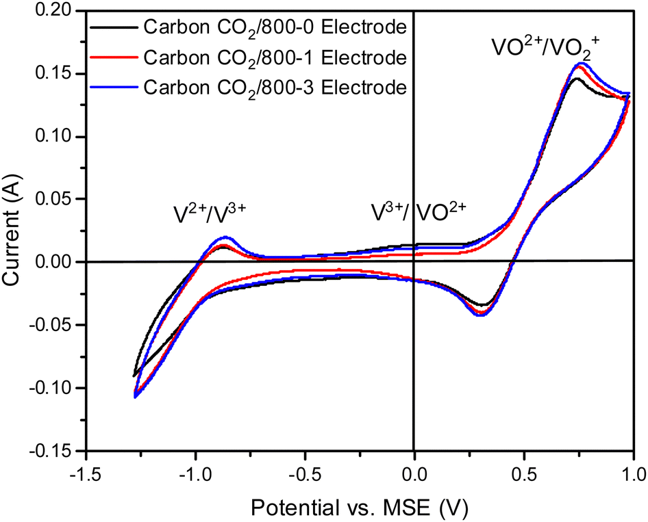 | ||
| Fig. 7 Comparison of cyclic voltammograms of electrodes prepared from carbons with HTT 800 °C and various hold times (carbons CO2/800-0, CO2/800-1, and CO2/1000-3) for vanadium redox reactions, Sweep rate 20 mV s−1. | ||
Three series of carbon samples were used in this study to explore the role of carbonization conditions and chemical treatment procedures on carbon in carbon/PVDF composite electrode properties. Cyclic voltammetry was studied at three sweep rates: 5, 10, and 20 mV s−1. Consistent trends were obtained for all three sweep rates for carbons prepared under nitrogen and carbon dioxide atmospheres, with the highest currents obtained for 20 mV s−1 (Fig. S18, ESI†). Therefore, the 20 mV sweep rate was used for cyclic voltammetry.
The cyclic voltammograms with a sweep rate of 20 mV s−1 for electrodes made from carbons with HTTs 600, 800, and 1000 °C in a nitrogen atmosphere (Series 1) are shown in Fig. 8a. The CVs have a very weak V2+ → V3+ peak, a V3+/VO2+ was absent, and the strongest peak was the VO2+ → VO2+ peak. An increase in carbon HTT enhances the VO2+ → VO2+ peak at an HTT of 800 °C for Series 1 (N2 atmosphere) carbons, but an increase of HTT to 1000 °C appears to have, at most, a small effect. Similar trends were observed at CV sweep rates of 5 and 10 mV s−1 (Fig. S16, ESI†). A weak V2+ → V3+ peak was observed, but no V3+ → VO2+ peak was observed. Fig. 8b shows the corresponding EIS plots, showing a very distinct difference between carbons with HTTs of 600 and 800 °C. The modeling studies for the EIS are shown in Table S1 (ESI†). Overall, the electrodes with carbon HTT 800 °C were shifted to lower electrode resistance than either carbon 600 °C or carbon 1000 °C electrodes.
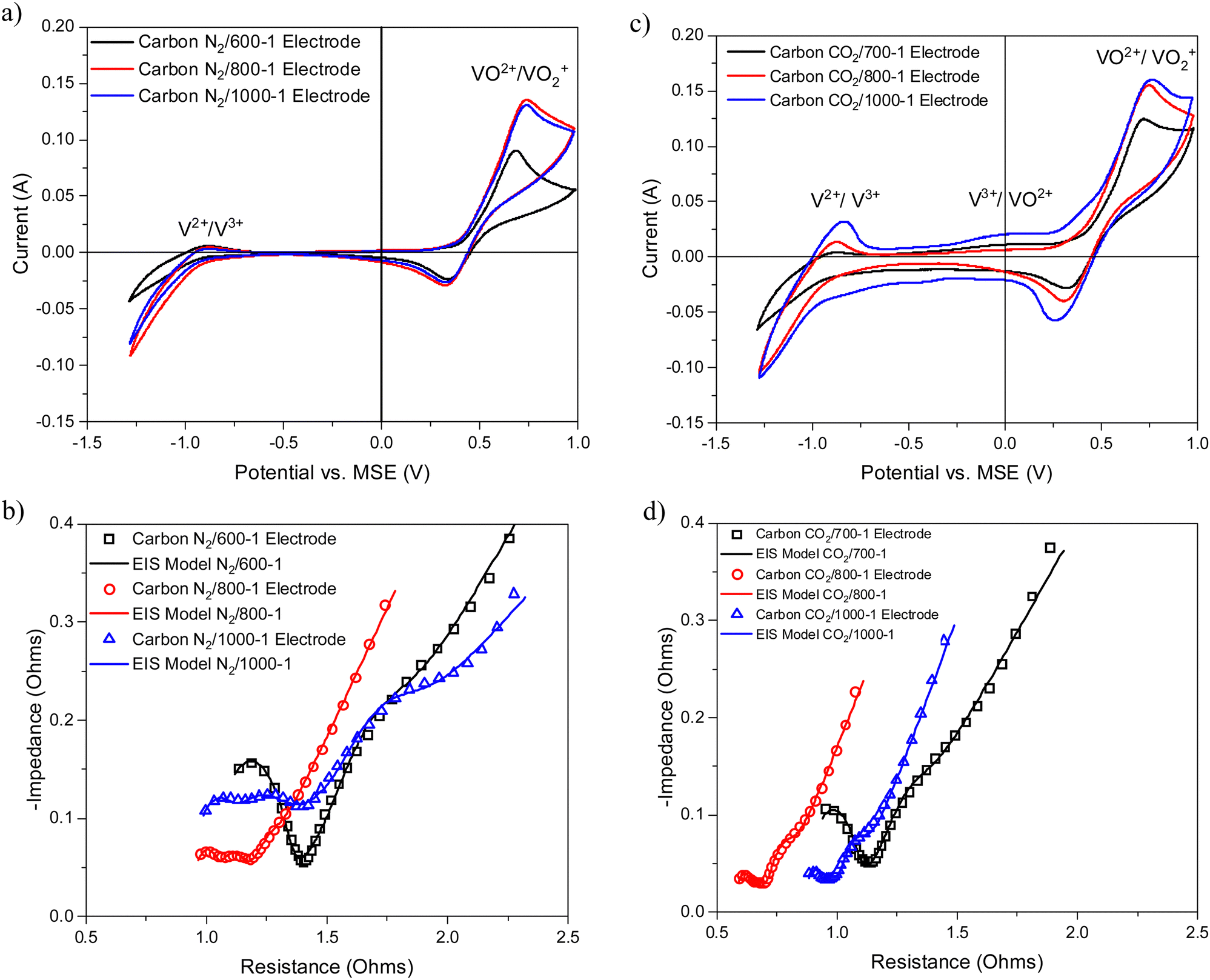 | ||
| Fig. 8 Comparison of electrochemical results for electrodes prepared from carbons prepared under nitrogen and carbon dioxide atmospheres (a) cyclic voltammograms of N2/600-1, N2/800-1, N2/1000-1 (b) Nyquist plots of N2/600-1, N2/800-1, N2/1000-1 and corresponding models; (c) cyclic voltammograms of CO2/700-1, CO2/800-1 and CO2/1000-1; and (d) Nyquist plots of CO2/700-1, CO2/800-1 and CO2/1000-1 and corresponding models. | ||
The CVs for electrodes made from carbons in Series 2 by carbonization at 700, 800, and 1000 °C in a carbon dioxide atmosphere are shown in Fig. 8c. The CVs for these carbon electrodes are slightly enhanced for the same temperatures compared to the carbon samples prepared in a nitrogen atmosphere (see Fig. 8a). An increase in HTT results in enhancement of the V2+ → V3+ peak in the CVs and the V3+/VO2+ couple is observed as an intermediate weak broad peak in carbon CO2/1000-1. There are only very small differences for VO2+ → VO2+ peak for HTTs of 800 and 1000 °C. The CVs for carbonization in N2 and CO2 at 800 and 1000 °C are shown in Fig. S18 (ESI†). The oxidation of V3+ to VO2+ was observed as a small peak at ∼0.1 V (vs. MSE) for carbons prepared under a CO2 atmosphere (Fig. 8c). This phenomenon has been reported previously.13,14,84 The corresponding Nyquist plots are shown in Fig. 8d. Comparison of the Nyquist plots for electrodes made from carbons prepared under N2 (Series 1) and CO2 (Series 2) at 800 and 1000 °C shows that the carbons with HTT 1000 °C are shifted to higher resistance (see Fig. S15b and d, ESI†). The Nyquist graphs show the same trend, with plots shifted to the lowest resistance for HTT 800 °C for carbonization in N2 and CO2 atmospheres. The electrical resistivity properties of high-density polyethylene/carbon black composite materials depend on carbon structure and surface functional groups. The resistivity properties of the composites can be modified using gasification and liquid phase chemical treatment of the carbon black.85,86 It is evident that the carbonization temperature for the carbon component of the carbon/PVDF electrodes has a major effect on cyclic voltammograms and Nyquist plots for vanadium redox reactions.
A weak shoulder on the low-frequency side of the Nyquist graph was observed at ∼15 Hz for the CO2 carbonization Series 2 and lower (∼2 Hz) for the corresponding N2 carbonization Series 1. The peak was very weak in carbon N2/800-1. The frequency shift for the N2 Series 1 compared with the CO2 Series 2 carbons is possibly due to differences in diffusion for these electrodes. The EIS of carbon N2/600-1 has a well-defined high-frequency peak, indicating a single time constant. However, electrodes prepared from carbons N2/800-1 and N2/1000-1 have two weak peaks (∼750 and 10000 Hz) indicative of the presence of two time constants. The carbons in Series 2 prepared under the CO2 atmosphere show a similar trend with HTT for electrodes prepared from carbons CO2/800-1 and CO2/1000-1 with very weak peaks in the high-frequency region.
The effect of HTT on CV and EIS is similar for carbonization in both N2 (Series 1) and CO2 (Series 2). Gas adsorption studies showed that both series of carbons were predominantly ultramicroporous (<0.7 nm), and therefore, there are liquid phase diffusion limitations into the porous structures (Section 3.2). Hence, changes in CV and EIS with HTT are not directly related to the carbon pore structure. However, porosity may be formed in the carbon/PVDF composite electrode, which may be influenced by differences in carbon surface chemistry. XPS shows that the surface oxygen functional groups are very similar for both carbon series for HTTs in the range of 700–1000 °C. However, minor differences were observed for Series 1 (N2 atmosphere) with HTTs 600 °C (Section 3.3.1.). Titration studies show that carbon CO2/700-1 has amphoteric properties, while at an HTT of 800 °C, there were virtually only basic characteristics (Table 6). The Raman spectra and PXRD data show that the amorphous carbon molecular structures change with increasing HTT (see Tables 7 and 8). The change in PXRD shows that crystallite size La increases with increasing HTT (Section 3.4.2.) The changes in Raman parameters (ID/IG, AD/AG, and FWHMD) change markedly over the HTT range 600–800 °C (Section 3.4.1), but only to a smaller extent up to 1000 °C. The cyclic voltammograms change markedly in the HTT range of 600–800 °C but only slightly over the temperature range (800–1000 °C). This transition temperature coincides with the minimum carbon electrode resistance measured by EIS and the change in carbon surface characteristics from acidic to basic. Therefore, the change in CV and EIS for carbons in Series 1 and 2 are attributed to changes in carbon molecular structure, giving rise to changes in electrode resistance.
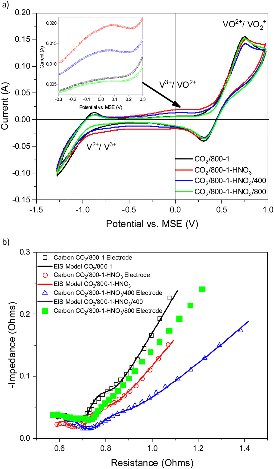 | ||
| Fig. 9 Comparison of electrochemical results for electrodes prepared from carbons CO2/800-1, CO2/800-1-HNO3, CO2/800-1-HNO3/400, and CO2/800-1-HNO3/800 prepared by oxidation in nitric acid and heat treatment (a) cyclic voltammograms with inset figure for potential range −0.3 to 0.3 V, and (b) Nyquist plots and corresponding models. | ||
Carbon CO2/800-1-HNO3 has a range of surface functional groups, including carboxylic, anhydride, lactone/lactol, and phenolic groups. Heat treatment in H2 to form carbon CO2/800-1-HNO3/400 resulted in the removal of mainly carboxylic and N-oxide groups, as shown by XPS, TPD, and titration studies. Heat treatment in H2 to form carbon CO2/800-1-HNO3/800 progressively removes labile oxygen functional groups. The pore structures were predominantly ultramicroporous (Table 2), limiting liquid phase diffusion. Only minor differences in Raman and XRD characterization data for this series of carbons were observed for the PXRD and Raman spectra of this series of carbons (Tables 7 and 8). Therefore, the differences in electrochemistry could not be accounted for by significant changes in either porous or molecular structures. This series of carbons allows an investigation of the role of oxygen surface functional groups in the vanadium redox reactions.
Therefore, reversible changes in CV for the V3+ → VO2+ couple were established by combining HNO3 oxidation and heat treatment in hydrogen. These changes follow the trend with oxygen functional group concentrations since the ultramicroporous structures limit diffusion, and changes in molecular structures are minimal. The progressive reversible changes in surface oxygen functional groups explain the differences in the CVs and Nyquist plots.
Carbon CO2/800-1 was treated with K2CO3 at 800 °C to form carbon CO2/800-1-K2CO3/800, and the cyclic voltammograms and Nyquist plots for the electrodes prepared for these carbons are shown in Fig. 10a and b. The modeling studies showed that the electrode resistances of carbons CO2/800-1 and CO2/800-1-K2CO3/800 were similar (Table S1, ESI†). The two weak high frequency Nyquist peaks at 750 and 12000 Hz observed for CO2/800-1 have been replaced by a single peak at 23000 Hz in CO2/800-1-K2CO3/800. The weak low frequency peak mentioned earlier at 15 Hz corresponds to a shoulder at ∼10 Hz in CO2/800-1-K2CO3/800. The increased surface homogeneity is a possible explanation of the change in the high frequency region of the Nyquist plots of CO2/800-1-K2CO3/800 compared with CO2/800-1. Carbon CO2/800-1-K2CO3/800 had a more pronounced CV peak for V3+/VO2+ than carbon CO2/800-1.
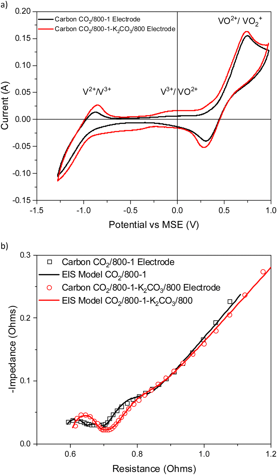 | ||
| Fig. 10 Comparison of electrochemical results for electrodes prepared from carbons CO2/800-1 and CO2/800-1-K2CO3/800 (a) cyclic voltammograms and (b) Nyquist plots and corresponding models. | ||
K2CO3 treatment at 800 °C only leads to small changes in the porous structure, and both samples are predominantly ultramicroporous (Table 2). The PXRD and Raman results for the carbon do not show significant differences (Tables 7 and 8). These results indicate minimal changes in the porous and molecular structures. The titration results showed that carbon CO2/800-1-K2CO3/800 has amphoteric surface characteristics containing both acidic (phenolic, lactone/lactol, and carboxyl) groups and basic groups (Table 6), whereas carbon CO2/800-1 had predominantly basic surface characteristics.
Carbon N2/800-1 was treated with NH3 to form carbon N2/800-1-NH3/800, and the cyclic voltammograms and Nyquist plots for the corresponding electrodes for vanadium redox reactions are shown in Fig. 11a and b, respectively. The V3+ → VO2+ transition is absent for the CV profile of carbon N2/800-1 but was observed as a very broad peak at ∼0.1 V in N2/800-1-NH3/800. Also, the V2+ → V3+ CV peak increased more than the VO2+ →VO2+ peak. The EIS profile of the N2/800-1-NH3/800 electrode was shifted to a higher resistance compared to the N2/800-1 electrode (Table S1, ESI†). The two high-frequency weak peaks in the EIS of the N2/800-1 electrode coincide with a peak for the N2/800-1-NH3/800 electrode, consistent with a more homogeneous surface in the NH3 treated carbon. Also, a weak low frequency peak at ∼2 Hz EIS associated with diffusion/kinetics was present as a clear shoulder.
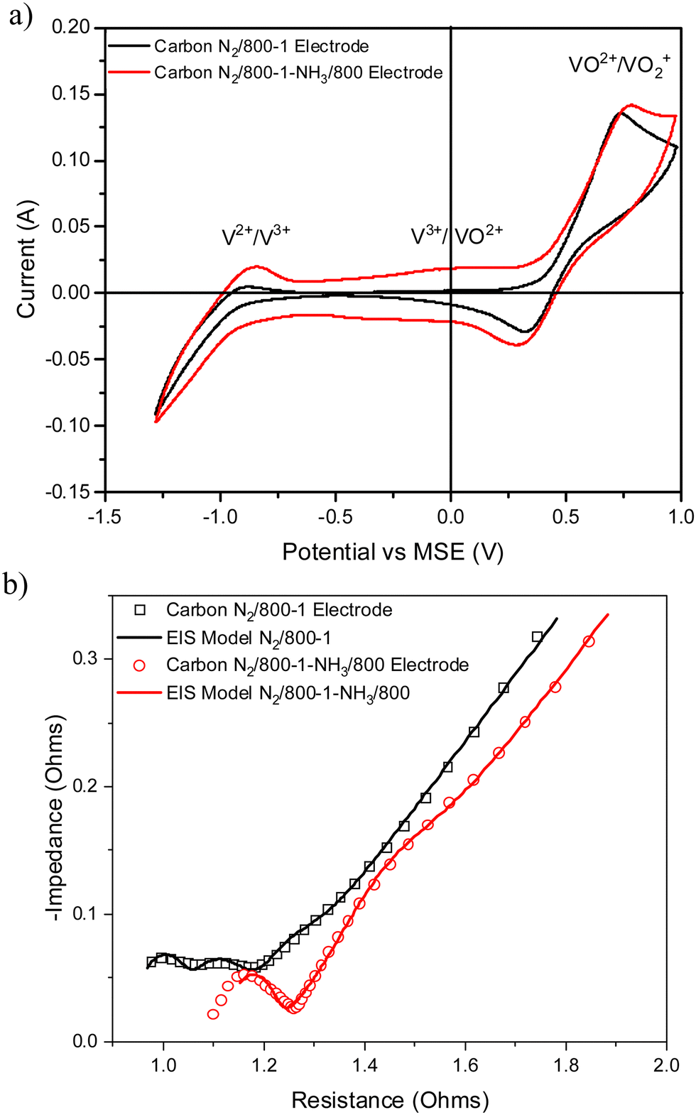 | ||
| Fig. 11 Comparison of electrochemical results for electrodes prepared from carbons N2/800-1 and N2/800-1-NH3/800 (a) cyclic voltammograms and (b) Nyquist plots and corresponding models. | ||
Ammonia treatment had a marked effect on carbon functional groups but a minimal effect on the predominantly ultramicroporous and molecular structures compared with carbon N2/800-1. The original carbon N2/800-1 had very low surface and bulk nitrogen contents, while the surface oxygen and bulk contents were much higher. The NH3 treatment of carbon N2/800-1 at 600 and 800 °C incorporates mainly pyridinic and pyrrolic nitrogen groups (ratio ∼2:1) into the carbon structure, with the surface analysis giving 2.56 and 4.86 at% for carbons N2/800-1-NH3/600 and N2/800-1-NH3/800, respectively (Table 5).
3.6. Electrode performance
VRFB static cell charge–discharge analysis was performed at current densities of 10, 15, and 20 mA cm−2 to evaluate the electrochemical performance of the carbons (see Fig. 12) Repeatability studies are shown in ESI,† Tables S2 and S3. The coulombic efficiency increases with increasing current density whereas the voltage efficiency decreases with increasing current density. It is apparent that the four carbon samples (N2/800-1, N2/800-1-NH3/800, CO2/800-1-HNO3, and CO2/800-1-HNO3/800), which had a range of functional groups, had similar voltage, coulombic and overall energy efficiencies. Stable energy efficiencies of all carbon samples were observed in the range of 89.5–90.9% at current densities of 10–15 mA cm−2 before slightly decreasing to 88.4–90.1% at 20 mA cm−2, but the overall efficiency differences are comparable to the experimental uncertainties. The slight decrease in energy efficiencies with increasing current densities can be ascribed to ohmic polarization,87 dynamic voltage (IR) drop at higher current densities,13,19 or electrolyte ions passing through the membrane.88 It also explains the decline of voltage efficiencies with increasing current densities. The CV and EIS results for electrodes prepared from carbons N2/800-1-NH3/800 and CO2/800-1-HNO3 demonstrated the influences of nitrogen and oxygen carbon functionality on the V2+/V3+ and VO2+/VO2+ couples. The microporosity in these carbons (ultra-micropores account for >75% of total pore volume) restricts the liquid phase diffusion of vanadium ions into the porous structure of the carbons, which explains the negligible differences in charge–discharge performance in these samples. The performance of walnut shell carbons prepared in this study is compared with that of other carbon materials using VRFB static cells in Table 9. The slightly lower energy efficiency of walnut shell carbons compared to orange peel carbon13 and spent coffee bean carbon20 is attributed to the high ultramicropore content limiting diffusion of vanadium ions in the carbon structure. The energy efficiency for walnut shell carbon demonstrated that it is suitable for VRFB electrodes. Carbon N2/800-1 had the highest efficiency and was subjected to extended tests for 20 cycles at each current density of 10, 15, and 20 mA cm−2, which are presented in Fig. 12d. The coulombic efficiency increases whereas the voltage efficiency decreases with increasing current density. The overall energy efficiency decreases with increasing current density, possibly due to the side reactions at each half-cell.89 The stable performance of walnut shell carbons suggests their suitability for use in VRFBs. The coulombic, voltage, and overall energy efficiencies of all the carbons (N2/800-1, N2/800-1-NH3/800, CO2/800-1-HNO3 and CO2/800-1-HNO3/800) studied were not significantly different within experimental error, and therefore longer-term stability tests were not undertaken.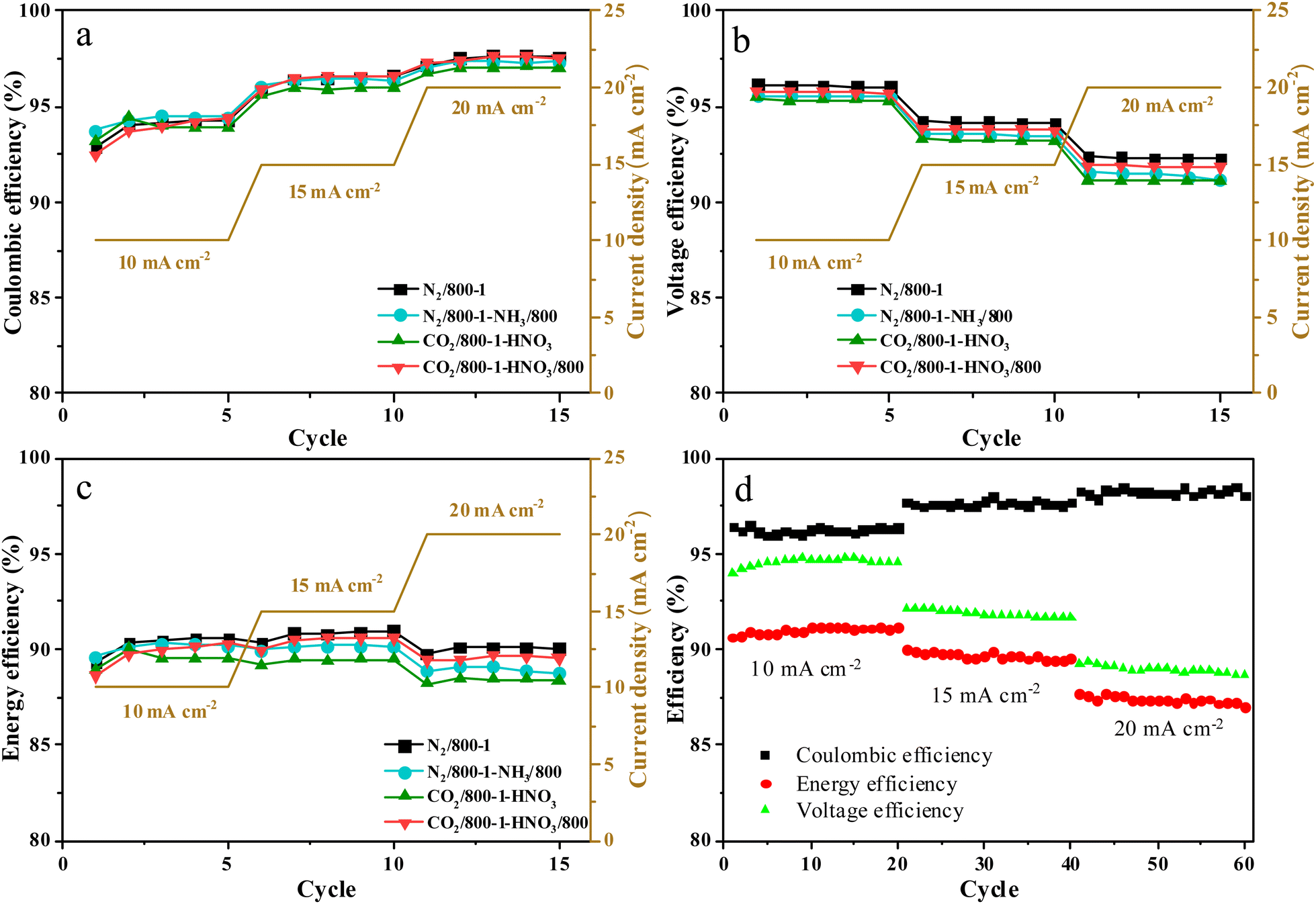 | ||
| Fig. 12 Comparison of cell performance for carbons N2/800-1, N2/800-1-NH3/800, CO2/800-1-HNO3 and CO2/800-1-HNO3/800. (a) Coulombic, (b) voltage, (c) energy efficiency, and (d) stability test of N2/800-1 for 20 cycles at each current density of 10, 15, and 20 mA cm−2. | ||
| Activated carbon material | Coulombic efficiency (%) | Energy efficiency (%) | Voltage efficiency (%) | Ref. |
|---|---|---|---|---|
| Spent tea leaf AC | 98 | 90 | 92 | 90 |
| Sal wood sawdust AC | 95.6 | 91.2 | 95.4 | 19 |
| Orange peel AC | 99.8 | 95.5 | 95.6 | 13 |
| Spent coffee beans based – reduced graphene oxide | 98 | 93 | 94 | 91 |
| Nitrogen-doped reduced graphene oxide – graphite felt | 92.09 | 76.08 | 82.62 | 92 |
| Nitrogen-doped graphite felt | 94.20 | 86.47 | 91.79 | 93 |
| Oxygen-functionalized carbon nanofiber | — | 75.5 | — | 94 |
| Walnut shell carbon N2/800-1 | 96.5 | 90.9 | 94.2 | This study |
3.7. The influence of carbon structural characteristics on vanadium redox reactions
Developing relationships between carbon surface chemistry, molecular structure, and porosity, with electrochemical characteristics, is essential for understanding the mechanism. Several investigations have focused on the relationship between electrochemistry and electrode properties for vanadium Redox reactions.9–11,13,14,17–20,27,94–115 In concentrated VRFB-relevant electrolyte solutions, polymerization, hydrolytic, and ion association processes are often extensive. Also, the capacities of VFBRs decay with use, and surface reactions are thought to be involved.26,116 The role of surface carbon groups on the electrode is unclear.27 The problem with investigating the roles of surface chemistry and carbon structure for vanadium redox electrochemical characteristics is that there is often a mixture of oxygen surface functional groups and a variety of carbon sites in an amorphous porous structure. Oxygen functional groups could enhance the wettability of carbons and act as electro-catalytic sites for redox reactions,100–102,105,114 but the influence of oxygen functional groups was only observed for carbon materials with low surface area or well-defined structure. Studies of the vanadium redox electrochemistry of polyacrylonitrile electrospun fibers led to the proposal that functional groups were the dominant factor for carbonization temperatures in the range 1000–1300 °C, but carbon edge sites were more critical over the temperature range 1300–1500 °C.100 Nitrogen and oxygen functional groups were incorporated into graphite felt by wet impregnation of urea followed by heat treatment in nitrogen to 500–700 °C. Electrochemical results suggested that pyrrolic and pyridinic functional groups were active centers for vanadium redox reactions.95 Li et al. attributed enhanced kinetics for V2+/V3+ to C–OH groups incorporated on the surface of carbon felt following thermal activation.101 This commercial carbon felt had a low surface area and was thermally resilient, and the improved kinetics of V2+/V3+ were attributed to the increase of oxygen functional groups. The enhanced kinetics of vanadium redox reactions have been ascribed to carboxyl groups present in multi-walled carbon nanotubes.102Simulation studies showed that nitrogen incorporated in the carbon structure had a positive impact on vanadium redox reactions.10 Shao et al. attributed the enhanced VO2+/VO2+ couple (the positive side of VRFB) to nitrogen doping in the mesoporous carbon. However, the BET surface area could have contributed significantly to their performance as it increased from 500 m2 g−1 for the untreated material to 1100 m2 g−1 for the NH3 treated carbon.104 The improvement in CV profiles of biomass-derived carbon was attributed to the mesopore structure.13,14 Costa de Oliveira et al. used voltammetry and EIS methods to reveal that N-functionalities significantly enhance the intrinsic activity of carbon electrode surfaces.117 Pyridinic/pyrrolic groups improved charge transfer rates and reversibility of the vanadyl oxidation reaction. These factors are crucial for important applications such as vanadium redox flow batteries. In comparison, oxygen functional groups may negatively impact vanadyl redox reactions.118
Steimecke et al. used scanning electrochemical microscopy (SECM) to investigate the VO2+/VO2+ reaction for various oxidized carbon materials.119 Electron transfer coefficients of glassy carbon (GC) and graphite substrates and their oxidized derivatives were comparable to cyclic voltammetry. In the case of oxidized samples, the results depended on the material. A small improvement was observed for oxidized GC whereas no effect was observed for graphite where the oxygen content increases from 4.0 to 13.0 at%. A combined in situ-Raman-SECM was also performed for a graphene layer. The graphene edge sites had increased activity at relatively low overpotentials for VO2+ oxidation and at high overpotentials for VO2+ reduction compared with basal plane carbon sites.
The relationship between vanadium redox reactions and carbon properties, the active electrode component of the carbon/PVDF electrode, is a multifactorial problem and is not well understood. In this study, the effects of carbonization or heat treatment temperature, porous structure, and functional groups have been considered in detail. The carbons in Series 1 and 2 used in this study were predominantly ultramicroporous (<0.7 nm), and, therefore, carbon porosity was not a factor influencing the CV measurements of vanadium redox reactions due to diffusion limitations. However, the porosity in the composite electrode formed between the polymer and the carbon is difficult to quantify. Carbon surface chemistry may influence porosity formation in the carbon/PVDF electrodes. There is no evidence that differences in the porous structure of the carbons used in this study are significant in determining EIS characteristics. Low frequency peaks in EIS may be associated with porosity in the carbon/PVDF electrodes. Carbon surface chemistry is known to alter the resistivity in carbon black/polymer composites.85,86
Cyclic voltammograms reported in the literature show that the relative peaks for V2+ → V3+, V3+ → VO2+, and VO2+ → VO2+ vary markedly depending on the structure of the carbon electrodes and the CV sweep rates, indicating kinetic effects.13,14,110 The vanadium V3+/VO2+ couple has potentiometric reversibility, but there is a large activation energy, and therefore, the kinetics are slow. Sufficiently negative potentials are required to bring the reduction of V(IV) to V(III), but in most cases, the negative potential is low enough to cause the reduction all the way to V(II). The V3+/VO2+ couple influences the initial pre-charging of the electrolyte.109 Previous studies of pre-oxidized glassy carbon electrodes showed that increased surface roughness was beneficial, while functional groups such as CO and C–O–C tend to reduce the activity of glassy carbon.114 Three concurrent processes occur, (1) slow V(III) → V(IV), (2) oxidation V(IV)→ V(V), and (3) reaction of V(III) and V(V) to form V(IV) species.109 The reversibility of the CV for V3+/VO2+ was improved by increased vanadium concentrations or oxygen functional groups.109 Various hydrolytic and ion association processes may occur in concentrated vanadium electrolyte solutions, and chemical stability is a factor.27,111,112 The connection between vanadium speciation in the electrolyte and surface groups in carbon electrodes is unclear. The relationship between vanadium species present in the electrolyte, electrode surface groups, and electrochemical kinetics needs systematic investigation. It has been proposed that the anodic reaction limits kinetics even at low current densities, and the cathodic reaction has mass transport effects at high current densities.27,113
This study investigated the use of sustainable biochar electrodes for vanadium redox reactions. Biomass pyrolysis involves the overlapping decomposition of lignocellulosic materials to form a carbonaceous char by an HTT of 600 °C. As the temperature increases, structural change leads to carbons with heterogeneous surfaces, which contain a wide range of oxygen and nitrogen surface sites and graphene layer sites, including zig-zag and armchair sites with unsatisfied valences at the edges of these layers. The heterogeneous amorphous structure of carbon leads to difficulties in structural characterization, and the techniques available have limitations. Therefore, it is very challenging to quantify the carbon structure of biochars.
The carbons used in this study were sustainable, amorphous, and non-graphitizable biochars, and quantifying the carbon structure is complicated. All carbons in Series 1 and 2 had a high proportion of ultramicroporosity (<0.7 nm), indicating diffusion limitations for liquid phases. XPS C 1s and O 1s studies indicate that surface oxygen functional groups are similar within experimental error for heat-treated carbons in Series 1 and Series 2 (Table S5, ESI†), although some differences are observed in the characterization data using titration methods (Table 6). Therefore, differences in porous structure characteristics and surface oxygen functional groups are not responsible for the significant changes in CV and EIS with HTT. The effect of HTT on carbon structure involves the loss of volatile decomposition products, as shown in the thermogravimetric and TPD data. The Raman characterization parameters show more significant changes in peak intensity (ID/IG) and area (AD/AG) ratios and D bandwidths for the HTT range 600–800 °C than for 800–1000 °C. The apparent crystallite size (La) changes progressively with HTT. The most significant changes in the CVs for vanadium redox reactions were observed for both Series 1 and Series 2 carbons for HTTs in the 600–800 °C temperature range with minor changes for HTT 800–1000 °C, and this change was independent of CV sweep rate. The electrical impedance measurements show that the electrode resistance reaches a minimum for carbons in Series 1 and 2 with a HTT of 800 °C (see Fig. 8b and d). These changes in carbon electrochemical properties coincide with the carbon HTT for maximum CVs. The electrodes used are carbon/PVDF polymer composites, and the resistivity of these materials depends on carbon structure, polymer matrix, and the volume fraction of carbon. Resistivity is related to the extent of conductive pathways between carbon particles, and carbon composite electrodes must be defect-free. The volume resistivity of the composite may be affected by both the surface groups and the carbon structure. Previous studies have reported carbon/polymer composite volume resistivity measurements, which change with the extent of carbon black gasification and surface functional groups incorporated by HNO3 treatment.85,86 The CV reaches a maximum, and the electrode resistance from EIS measurements a minimum at ∼800 °C. Therefore, it is proposed that the electrical conductivity of the carbon particles in the electrode is responsible for the major changes in CV with HTT in Series 1 and 2 carbons.
A requirement for assessing the impact of oxygen and nitrogen functional groups incorporated into carbon structure on electrochemistry was that the HTTs should not be exceeded by the treatment temperature since this could cause further carbon molecular structural change, which could obscure the impact of functional groups. Carbons N2/800-1 and CO2/800-1 were chosen because the cyclic voltammograms do not change markedly for HTT > 800 °C. All the carbons used were predominantly ultramicroporous, and the NH3 and K2CO3 functionalization treatment conditions were also 800 °C. The maximum heat treatment of carbon CO2/800-1-HNO3 was also limited to 800 °C. All the treatment procedures had minimal effects on the porous and molecular structures. The main difference observed in the CV for the functionalized carbons was the enhancement of the V3+/VO2+ couple, and this was ascribed to the interaction of the nitrogen and oxygen surface groups with V(H2O)63+ and VO(H2O)52+.
Oxidation of carbon CO2/800-1 with HNO3 to form carbon CO2/800-1-HNO3 increased the CV V3+/VO2+ couple, and this was reversed by heat treatment in H2 at 400 and 800 °C. The EIS showed that the electrode resistances were only changed slightly by functionalization. In this series of carbons, surface oxygen groups were incorporated by HNO3 oxidation, and labile oxygen surface oxygen groups with different thermal stabilities were removed by heat treatment in H2. The changes in CV followed corresponding changes in surface oxygen functional groups, with only minor molecular structure changes observed. The series had a wide range of bulk oxygen contents from chemical analysis (7.54–23.84 wt%, see Table 1) and surface oxygen contents from XPS (2.85–13.54 at%, see Table 3), and the surface and bulk oxygen contents have a linear correlation (R2 = 0.976) (Fig. S43, ESI†). Fig. 13 shows that the CV changes linearly with surface oxygen (R2 = 0.999) and the oxygen groups with peaks at 531.1 eV (CO) (R2 = 0.999) and 533.5 eV (O–C attached to aromatic groups) (R2 = 0.999). However, the peak at 532.3 eV, ascribed to O–C aliphatic groups, does not change markedly (R2= 0.624), which suggests that O–C aliphatic groups are not responsible while carboxylic groups are involved. Various functional groups, for example, carboxylic, lactone, etc., have these types of oxygen. The XPS peak at ∼535.6 eV also showed a linear correlation (R2 = 0.992) with CV current, but this only represented ∼5% of the total O 1s peak area. The XPS C 1s peak (289 eV) shows that the carboxylic acid groups were 6 at% in carbon CO2/800-1-HNO3, 1.3 at% in CO2/800-1-HNO3/400, and 0.19 at% in CO2/800-1-HNO3/800 (Fig. S43, ESI†) and this is due to thermal decomposition. The intensity of this XPS C 1s peak has a linear correlation with carboxylic groups determined by titration methods (R2 = 0.999, See Section 3.3.2 and Fig. S43, ESI†). The decomposition of the COOH groups is supported by the loss of CO2 in TPD (see Fig. 4) and the loss of an FTIR CO carboxylic peak observed at 1713 cm−1 for carbon CO2/800-1-HNO3 (Fig. S41d, ESI†). The titration measurements showed that the weakly acidic phenolic groups had little or no effect on the CV for the carbon CO2/800-1-HNO3 oxidation series. The TPD results show the decomposition of N-oxide groups, carboxylic, and other oxygen groups with CO, CO2, and NO loss. Comparison of the XPS N 1s of carbons CO2/800-1-HNO3 and CO2/800-1-HNO3/400 showed that the N-oxide peak had decomposed at 400 °C. (Fig. S27 and Table 5, ESI†). Previous studies have shown that the adsorption of metal ions on carbon was dramatically increased by HNO3 oxidation, and carboxylic acid groups were shown to strongly adsorb various M2+ ions, where M2+ = Cd, Pb, Hg, and Ca through ion exchange.33,120 The adsorption of metal ions was decreased significantly by heat treatment of the carbon. This established a relation between carboxylic acid functional groups and metal ion adsorption.33 Adsorption of vanadium species on surface carboxylic oxygen groups is a possible interaction mechanism that explains trends in the CVs and Nyquist plots. The underlying process at high potential is most likely the kinetically limited V(III) to V(IV) oxidation and then proceeding to V(V). The oxidation of V(III) to V(IV) only occurs on a limited number of oxygen surface sites, and the outer-sphere electron transfer to oxidize V(III) takes place at much more positive potentials.
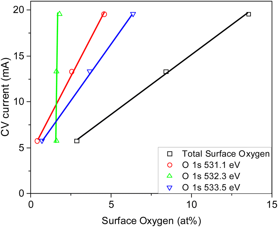 | ||
| Fig. 13 Comparison of cyclic voltammetry for the HNO3 functionalized carbon series and XPS oxygen surface analysis and functional groups obtained from O 1s spectra. | ||
K2CO3 treatment of carbon CO2/800-1 at 800 °C enhanced the CV peaks, particularly the V3+/VO2+ couple, and EIS showed that the electrode resistance increased slightly. Since both carbons CO2/800-1 and CO2/800-1-K2CO3/800 have similar ultramicroporous (Table 2) and molecular structures (Tables 7 and 8), the changes in CV are attributed to differences in functional groups. The XPS showed a small decrease in surface oxygen groups from 8.3 at% for carbon CO2/800-1 to 7.07% for CO2/800-1-K2CO3/800. Comparison of XPS C 1s spectra of carbons CO2/800-1 and CO2/800-1-K2CO3/800 did not show significant differences in the distribution of surface functional groups. The XPS O 1s scan showed a decreased CO intensity (531 eV), while the CO/OH attached aliphatic (532.2 eV) and C-O attached to aromatic (533.5 eV) increased significantly with the K2CO3 treatment. In comparison, the HNO3 oxidation series showed that the 531.1 and 533.5 eV peaks correlated with a change in CV, whereas the 532.3 eV peaks did not. However, this must be considered in the context that some of the functional groups incorporated by chemical oxidation are thermally labile, whereas the K2CO3 treatment was carried out at 800 °C. A comparison of carbons with the same HTT shows that carbons CO2/800-1-HNO3/800 and CO2/800-1 have main TPD CO2 peaks at 825 and 818 °C. The TPD for carbon CO2/800-1-K2CO3/800 shows CO2 desorption starting at ∼550 °C with peaks at 725 and 875 °C. The TPD peak at 725 °C does not coincide with the desorption of H2O or CO. The titration results showed carbon CO2/800-1-K2CO3/800 had acidic (mainly phenolic and carboxylic with a small amount of lactone/lactol) and basic groups, whereas carbons CO2/800-1 only had basic groups and CO2/800-1-HNO3/800 had phenolic and some basic amphoteric characteristics. This suggests that the difference is due to the CO2 peak at 725 °C being associated with the strongly acidic groups as characterized by titration are responsible for changes in CV. The FTIR results do not show strong CO stretching bands in the 1600–1800 cm−1 region, indicating the absence of carboxylic and anhydrides, but the spectra are weak. The characterization techniques show that the TPD CO2 desorption peak at 725 °C, the presence of acidic functional groups, and the increased intensity XPS O 1s 533.5 eV peak are related to changes in CV. The oxygen functional groups act as sites in carbon CO2/800-1-K2CO3/800 for oxidizing V(III) to V(IV).
Treatment of carbon N2/800-1 with ammonia at 800 °C to form carbon N2/800-1-NH3/800 has a significant effect in increasing the V3+ → VO2+ CV peak, which was not observed for the starting carbon N2/800-1 and increases the V2+ → V3+ CV peak more than the VO2+ → VO2+peak. The EIS showed that NH3 treatment increased electrode resistance. NH3 treatments decreased the surface oxygen from 8.1 at% in carbon N2/800-1 to 2.7 and 1.8 at% in carbons N2/800-1-NH3/600 and N2/800-1-NH3/800, respectively. Curve resolution of the XPS C 1s and O 1s peaks show that the distribution of the oxygen functional groups for carbons N2/800-1, N2/800-1-NH3/600, and N2/800-1-NH3/800 were similar. XPS N 1s studies show that the NH3 reaction incorporates mainly pyridinic and pyrrolic nitrogen groups into the carbon structure with a ratio ∼2:1 with total nitrogen 2.56 at% for 600 °C and 4.86 at% for 800 °C. The titration measurements show that the surface of carbon N2/800-1-NH3/800 had amphoteric characteristics with weakly acidic phenolic groups and basic pyridinic groups on the surface of carbon N2/800-1-NH3/800. The basic characteristics were slightly higher for N2/800-1-NH3/800 carbon than N2/800-1 due to the pyridinic groups.
Surface nitrogen functional groups in activated carbons incorporated by high-temperature ammonia treatment increased the adsorption of capacities of M2+ metal ion species (M = Cd, Ni, and Cu), and it was proposed that pyridinic groups were responsible.34 A similar interaction of vanadium species with pyridinic groups may explain the differences between the CVs and Nyquist plots before and after NH3 treatment. The changes in electrochemistry can be attributed to incorporating nitrogen as pyridinic and pyrrolic groups into the carbon structure while reducing surface oxygen groups markedly, which catalyzes V3+ oxidation on the surface of electrodes. Pyridinic groups are the major nitrogen functional groups in carbon N2/800-1-NH3/800.
4. Conclusions
The influence of the structural and surface chemical characteristics of sustainable biomass-derived carbons on vanadium redox reactions has been explored in this study. The two series of walnut shell-derived carbons made in N2 and CO2 atmospheres were predominantly ultramicroporous, and therefore, the porous structures had little or no effect on the vanadium redox electrochemical characteristics because of diffusion limitations. The XPS C 1s and O 1s showed minimal changes in surface oxygen functional groups. The effect of carbonization temperature on carbon molecular structure was shown by changes in Raman and X-ray diffraction parameters. The most intense couple in the CV for the vanadium redox electrochemistry was VO2+/VO2+, where the current increased markedly for carbonization under N2 and CO2 in the temperature range of 600–800 °C. However, only minimal changes were observed when increasing the HTT from 800 °C to 1000 °C. These changes are the most significant in cyclic voltammetry. Electrical impedance measurements showed that the electrode resistance reached a minimum at HTT 800 °C. Biochar carbonization temperature has the primary effect on electrochemical properties. This effect is attributed to the modification of the carbon molecular structure, increasing electrical conductivity over the HTT range of 600–800 °C.The role of surface groups in carbon structures was investigated by chemical oxidation and high-temperature treatment methods. Carbons with an HTT of 800 °C were used for functionalization studies since the cyclic voltammograms are close to the maximum CV current and avoid the effects of molecular structural change due to HTT. Oxidation of carbon CO2/800-1 with nitric acid resulted in incorporating a mixture of labile acidic carboxylic, lactone, lactol, and anhydride functional groups into the carbon structure, and the CV current of the V3+/VO2+ couple also increased significantly. Minor changes in CV were also observed for the V2+/V3+ and VO2+/VO2+ couples. These changes in CV were partly reversed when the oxidized carbon sample was heat treated in H2 to 400 °C, removing carboxylic groups. Thermolysis at 800 °C in H2 removed further oxygen functional groups, with the CV and Nyquist graphs being similar to the original carbon CO2/800-1, indicating some reversibility. The changes in the CV for the V3+/VO2+ couple are related to changes in surface oxygen in the carbons. The relationship between surface carboxylic groups and CV changes, as shown by XPS, is supported by titration, TPD, and FTIR measurements. The underlying process at high potential is most likely the kinetically limited V(III) to V(IV) oxidation and then to V(V). The oxidation of V(III) to V(IV) only occurs on a limited number of oxygen surface sites, and the outer-sphere electron transfer to oxidize V(III) takes place only at much more positive potentials.
Similarly, electrodes prepared with carbon CO2/800-1-K2CO3/800 had small increases in the CV currents for V2+/V3+, V3+/VO2+, and VO2+/VO2+ couples compared with electrodes made from carbon CO2/800-1. XPS, titration, and TPD studies showed that K2CO3 treatment incorporated thermally stable acidic surface oxygen functional groups in the carbon structure. The changes in cyclic voltammetry were attributed to changes in oxygen functional groups.
NH3 treatment of carbon N2/800-1 at 600 and 800 °C resulted in the incorporation of nitrogen mainly as surface pyridinic and pyrrolic groups in the carbon structure and the removal of a large proportion of surface oxygen groups. The CV for carbon N2/800-1-NH3/800 showed the presence of a broad V3+/VO2+ peak absent in the starting material carbon N2/800-1. Incorporating nitrogen functional groups into the carbon structure has a similar effect to incorporating oxygen functional groups into the carbon structure and involves catalysis of V3+/VO2+ oxidation on the nitrogen surface sites of the electrodes.
The coulombic, voltage, efficiency, and energy efficiency for walnut shell carbons were suitable for VFRBs, and good stability was observed. The functionalization of the carbons only had minor effects on voltage, efficiency, and energy efficiency for both the HNO3 oxidized and NH3 treated carbons. The study of carbon structure and functional group relationships with vanadium redox electrochemistry supports the development of improved electrode materials for vanadium redox flow batteries.
Author contributions
Ha H. Phan: investigation, methodology, data curation and analysis, original draft. Jon G. Bell: supervision (Porosity Characterization). Greg A. Mutch: investigation (Raman measurements). Alan J. McCue: investigation (FTIR measurements). Anh N. Phan: conceptualization, supervision, discussion, analysis, writing, reviewing, editing. K. Mark Thomas: conceptualization, supervision, discussion, formal analysis, modelling, writing, reviewing, editing.Data availability
ESI† includes all the significant data for the paper in graphical or table format. The data that support the findings of this study are available from the corresponding author upon request.Conflicts of interest
The authors declare no competing financial interest.Acknowledgements
This work was jointly funded by the Newcastle University Research Excellence Academy Award, reference (EJU/160538009), and the School of Chemical Engineering and Advanced Materials, Newcastle University. HHP thanks the Santander Mobility Award for funding the visit to Nanyang Technological University (NTU) and Energy Research Institute (ERI@N), Singapore, in 2017/2018, and Prof Ulrich Stimming and his research group for access to the electrochemical facilities. The authors would like to thank the Academy of Medical Sciences for the GCRF Networking Grant (GCRFNGR3\1506), the Royal Academy of Engineering for the research grant (FF\1920\1\45), and EPSRC for Grant EP/K005499/1. The authors would also like to thank Professor Andrew Hamnett for many helpful discussions regarding the modeling of Electrical Impedance spectra. The authors would like to thank Maggie White for performing the XRD. XPS data were obtained at the EPSRC National Facility for XPS (‘HarwellXPS’), operated by Cardiff University and UCL, UK, under contract No. PR16195. TEM analysis was performed at the Electron Microscopy Centre, School of Materials, University of Manchester, UK. This work was supported by the Engineering & Physical Sciences Research Council [grant numbers EP/V047078/1, EP/W03395X/1]. GAM was supported by the Royal Academy Research Fellowship Scheme (EP/M50791X/1).References
- P. Leung, X. H. Li, C. P. de Leon, L. Berlouis, C. T. J. Low and F. C. Walsh, Rsc Adv., 2012, 2, 10125–10156 RSC.
- D. C. Holzman, Environ. Health Perspect., 2007, 115, A358–A361 Search PubMed.
- K. Lourenssen, J. Williams, F. Ahmadpour, R. Clemmer and S. Tasnim, J. Energy Storage, 2019, 25, 17 Search PubMed.
- C. Doetsch and J. Burfeind, in Storing Energy, ed. T. M. Letcher, Elsevier, 2022, 2nd Edn, pp. 363–381 DOI:10.1016/B978-0-12-824510-1.00030-1.
- M. Skyllas-Kazacos, M. H. Chakrabarti, S. A. Hajimolana, F. S. Mjalli and M. Saleem, J. Electrochem. Soc., 2011, 158, R55–R79 CrossRef CAS.
- L. Y. Li, S. Kim, W. Wang, M. Vijayakumar, Z. M. Nie, B. W. Chen, J. L. Zhang, G. G. Xia, J. Z. Hu, G. Graff, J. Liu and Z. G. Yang, Adv. Energy Mater., 2011, 1, 394–400 CrossRef CAS.
- R. L. McCreery, Chem. Rev., 2008, 108, 2646–2687 CrossRef CAS PubMed.
- J. Noack, N. Roznyatovskaya, T. Herr and P. Fischer, Angew. Chem., Int. Ed., 2015, 54, 9775–9808 CrossRef PubMed.
- Y. Gao, H. R. Wang, Q. Ma, A. J. Wu, W. Zhang, C. X. Zhang, Z. H. Chen, X. X. Zeng, X. W. Wu and Y. P. Wu, Carbon, 2019, 148, 9–15 CrossRef CAS.
- A. Xu, L. Shi, L. Zeng and T. S. Zhao, Electrochim. Acta, 2019, 300, 389–395 CrossRef CAS.
- C. Zhao, Y. H. Li, Z. X. He, Y. Q. Jiang, L. Li, F. Y. Jiang, H. Z. Zhou, J. Zhu, W. Meng, L. Wang and L. Dai, J. Energy Chem., 2019, 29, 103–110 CrossRef.
- D. A. Laird, R. C. Brown, J. E. Amonette and J. Lehmann, Biofuels, Bioprod. Biorefin., 2009, 3, 547–562 CrossRef CAS.
- M. Maharjan, A. Bhattarai, M. Ulaganathan, N. Wai, M. O. Oo, J. Y. Wang and T. M. Lim, J. Power Sources, 2017, 362, 50–56 CrossRef CAS.
- M. Ulaganathan, A. Jain, V. Aravindan, S. Jayaraman, W. C. Ling, T. M. Lim, M. P. Srinivasan, Q. Y. Yan and S. Madhavi, J. Power Sources, 2015, 274, 846–850 CrossRef CAS.
- S. C. Roy, A. W. Harding, A. E. Russell and K. M. Thomas, J. Electrochem. Soc., 1997, 144, 2323–2328 CrossRef CAS.
- S. C. Roy, P. A. Christensen, A. Hamnett, K. M. Thomas and V. Trapp, J. Electrochem. Soc., 1996, 143, 3073–3079 CrossRef CAS.
- H. R. Jiang, W. Shyy, M. C. Wu, R. H. Zhang and T. S. Zhao, Appl. Energy, 2019, 233, 105–113 Search PubMed.
- Z. X. He, Y. Q. Jiang, J. Zhu, Y. H. Li, L. Dai, W. Meng, L. Wang and S. Q. Liu, ChemElectroChem, 2018, 5, 2464–2474 CrossRef CAS.
- M. Maharjan, N. Wai, A. Veksha, A. Giannis, T. M. Lim and G. Lisak, J. Electroanal. Chem., 2019, 834, 94–100 CrossRef CAS.
- V. Krikstolaityte, O. E. Y. Joshua, A. Veksha, N. Wai, G. Lisak and T. M. Lim, Batteries, 2018, 4, 11 CrossRef.
- P. J. Hall and J. M. Calo, Energy Fuels, 1989, 3, 370–376 CrossRef CAS.
- U. Zielke, K. J. Huttinger and W. P. Hoffman, Carbon, 1996, 34, 983–998 CrossRef CAS.
- J. H. Zhou, Z. J. Sui, J. Zhu, P. Li, C. De, Y. C. Dai and W. K. Yuan, Carbon, 2007, 45, 785–796 CrossRef CAS.
- P. M. Claesson, A. van der Waals and A. Fogden, in Handbook for Cleaning/Decontamination of Surfaces, ed. I. Johansson and P. Somasundaran, Elsevier Science B.V., Amsterdam, 2007, pp. 885–927 DOI:10.1016/B978-044451664-0/50027-9.
- Y. Gao, Y. Sun, W. Song, Y. Jia, A. Li and S. Wang, Chem. Eng. J., 2023, 475, 146356 CrossRef CAS.
- N. Remmler and M. Bron, ChemElectroChem, 2024, 11, 202400127 CrossRef.
- N. Roznyatovskaya, J. Noack, K. Pinkwart and J. Tubke, Curr. Opin. Electrochem., 2020, 19, 42–48 CrossRef CAS.
- R. M. Bachman, L. R. Radovic and D. M. Hall, ChemSusChem, 2023, 16, 8 CrossRef PubMed.
- B. P. Kirk and H. C. Wilkinson, Talanta, 1970, 17, 475 CrossRef CAS PubMed.
- H. P. Boehm, Carbon, 2002, 40, 145–149 CrossRef CAS.
- I. Y. Stein, A. J. Constable, N. Morales-Medina, C. V. Sackier, M. E. Devoe, H. M. Vincent and B. L. Wardle, Carbon, 2017, 117, 411–420 CrossRef CAS.
- N. Iwashita, C. R. Park, H. Fujimoto, M. Shiraishi and M. Inagaki, Carbon, 2004, 42, 701–714 CrossRef CAS.
- Y. F. Jia and K. M. Thomas, Langmuir, 2000, 16, 1114–1122 CrossRef CAS.
- Y. F. Jia, B. Xiao and K. M. Thomas, Langmuir, 2002, 18, 470–478 CrossRef CAS.
- B. Xiao, J. P. Boudou and K. M. Thomas, Langmuir, 2005, 21, 3400–3409 CrossRef CAS PubMed.
- X. Xiao, Z. M. Chen and B. L. Chen, Sci. Rep., 2016, 6, 13 CrossRef PubMed.
- M. Keiluweit, P. S. Nico, M. G. Johnson and M. Kleber, Environ. Sci. Technol., 2010, 44, 1247–1253 CrossRef CAS PubMed.
- J. Garrido, A. Linaressolano, J. M. Martinmartinez, M. Molinasabio, F. Rodriguezreinoso and R. Torregrosa, Langmuir, 1987, 3, 76–81 CrossRef CAS.
- F. Rodriguez-Reinoso and A. Linares-Solano, in The Chemistry and Physics of Carbon, ed. P. L. PThrower, Marcel Dekker, New York, 1989, vol. 21, pp. 1–146 Search PubMed.
- D. Cazorla-Amoros, J. Alcaniz-Monge, M. A. de la Casa-Lillo and A. Linares-Solano, Langmuir, 1998, 14, 4589–4596 CrossRef CAS.
- H. Marsh and W. F. K. Wynne-Jones, Carbon, 1964, 1, 269–279 CrossRef CAS.
- M. Thommes, K. Kaneko, A. V. Neimark, J. P. Olivier, F. Rodriguez-Reinoso, J. Rouquerol and K. S. W. Sing, Pure Appl. Chem., 2015, 87, 1051–1069 CrossRef CAS.
- H. Marsh, Carbon, 1987, 25, 49–58 CrossRef CAS.
- C. R. Reid and K. M. Thomas, Langmuir, 1999, 15, 3206–3218 CrossRef CAS.
- J. H. Perezlopez, L. J. Gonzalezortiz, M. A. Leiva and J. E. Puig, AIChE J., 1992, 38, 753–760 CrossRef CAS.
- E. Koseoglu and C. Akmil-Basar, Adv. Powder Technol., 2015, 26, 811–818 CrossRef CAS.
- A. S. Mestre, F. Hesse, C. Freire, C. O. Ania and A. P. Carvalho, J. Colloid Interface Sci., 2019, 536, 681–693 CrossRef CAS PubMed.
- Q. Zhu, K. Grant and K. M. Thomas, Carbon, 1995, 33, 35–46 CrossRef CAS.
- Q. Zhu, S. L. Money, A. E. Russell and K. M. Thomas, Langmuir, 1997, 13, 2149–2157 CrossRef CAS.
- K. A. Grant, Q. Zhu and K. M. Thomas, Carbon, 1994, 32, 883–895 CrossRef CAS.
- H. Kono, in Materials Science and Engineering of Carbon, ed. Inagaki, M. and F. Kang, Elsevier, 2016, ch. 8, pp. 153–171 Search PubMed.
- L. A. Averett, P. R. Griffiths and K. Hishikida, Anal. Chem., 2008, 80, 3045–3049 CrossRef PubMed.
- L. Caracciolo, L. Madec and H. Martinez, ACS Appl. Energy Mater., 2021, 4, 11693–11699 CrossRef CAS.
- P. M. A. Sherwood, Surf. Interface Anal., 2019, 51, 589–610 CrossRef CAS.
- M. Smith, L. Scudiero, J. Espinal, J. S. McEwen and M. Garcia-Perez, Carbon, 2016, 110, 155–171 CrossRef CAS.
- T. R. Gengenbach, G. H. Major, M. R. Linford and C. D. Easton, J. Vac. Sci. Technol., A, 2021, 39, 013204 CrossRef CAS.
- G. H. Major, N. Fairley, P. M. A. Sherwood, M. R. Linford, J. Terry, V. Fernandez and K. Artyushkova, J. Vac. Sci. Technol., A, 2022, 40, 057001 CrossRef CAS.
- G. H. Major, N. Farley, P. M. A. Sherwood, M. R. Linford, J. Terry, V. Fernandez and K. Artyushkova, J. Vac. Sci. Technol., A, 2020, 38, 061203 CrossRef CAS.
- D. Yang, A. Velamakanni, G. Bozoklu, S. Park, M. Stoller, R. D. Piner, S. Stankovich, I. Jung, D. A. Field, C. A. Ventrice and R. S. Ruoff, Carbon, 2009, 47, 145–152 CrossRef CAS.
- C. Kozlowski and P. M. A. Sherwood, Carbon, 1986, 24, 357–363 CrossRef CAS.
- Y. Q. Wang, F. Q. Zhang and P. M. A. Sherwood, Chem. Mater., 2001, 13, 832–841 CrossRef CAS.
- C. C. Huang, A. M. Puziy, O. I. Poddubnaya, D. Hulicova-Jurcakova, M. Sobiesiak and B. Gawdzik, Electrochim. Acta, 2018, 270, 339–351 CrossRef CAS.
- J. R. Pels, F. Kapteijn, J. A. Moulijn, Q. Zhu and K. M. Thomas, Carbon, 1995, 33, 1641–1653 CrossRef CAS.
- S. Kundu, Y. M. Wang, W. Xia and M. Muhler, J. Phys. Chem. C, 2008, 112, 16869–16878 CrossRef CAS.
- A. Contescu, C. Contescu, K. Putyera and J. A. Schwarz, Carbon, 1997, 35, 83–94 CrossRef CAS.
- A. Contescu, M. Vass, C. Contescu, K. Putyera and J. A. Schwarz, Carbon, 1998, 36, 247–258 CrossRef CAS.
- Y. Otake and R. G. Jenkins, Carbon, 1993, 31, 109–121 CrossRef CAS.
- J. L. Figueiredo, M. F. R. Pereira, M. M. A. Freitas and J. J. M. Orfao, Carbon, 1999, 37, 1379–1389 CrossRef CAS.
- B. Xiao and K. M. Thomas, Langmuir, 2005, 21, 3892–3902 CrossRef CAS PubMed.
- J. Zawadzki, in Chemistry and Physics of Carbon ed. T. P. A., Marcel Dekker inc., New York, 1989, vol. 21, pp. 147–380 Search PubMed.
- B. J. Meldrum and C. H. Rochester, Fuel, 1991, 70, 57–63 CrossRef CAS.
- B. J. Meldrum and C. H. Rochester, J. Chem. Soc., Faraday Trans., 1990, 86, 861–865 RSC.
- F. Tuinstra and J. L. Koenig, J. Chem. Phys., 1970, 53, 1126 CrossRef CAS.
- A. C. Ferrari and J. Robertson, Phys. Rev. B: Condens. Matter Mater. Phys., 2000, 61, 14095–14107 CrossRef CAS.
- M. W. Smith, I. Dallmeyer, T. J. Johnson, C. S. Brauer, J. S. McEwen, J. F. Espinal and M. Garcia-Perez, Carbon, 2016, 100, 678–692 CrossRef CAS.
- V. N. Tsaneva, W. Kwapinski, X. Teng and B. A. Glowacki, Carbon, 2014, 80, 617–628 CrossRef CAS.
- M. Kierkowicz, E. Pach, A. Santidrian, S. Sandoval, G. Goncalves, E. Tobias-Rossell, M. Kalbac, B. Ballesteros and G. Tobias, Carbon, 2018, 139, 922–932 CrossRef CAS.
- E. A. Arkhipova, A. S. Ivanov, N. E. Strokova, S. A. Chernyak, A. V. Shumyantsev, K. I. Maslakov, S. V. Savilov and V. V. Lunin, Carbon, 2017, 125, 20–31 CrossRef CAS.
- O. Fromm, A. Heckmann, U. C. Rodehorst, J. Frerichs, D. Becker, M. Winter and T. Placke, Carbon, 2018, 128, 147–163 CrossRef CAS.
- C. A. Johnson, J. W. Patrick and K. M. Thomas, Fuel, 1986, 65, 1284–1290 CrossRef CAS.
- A. Cuesta, P. Dhamelincourt, J. Laureyns, A. Martinezalonso and J. M. D. Tascon, Carbon, 1994, 32, 1523–1532 CrossRef CAS.
- M. R. Miladinovic, M. V. Zdujic, D. N. Veljovic, J. B. Krstic, I. B. Bankovic-Ilic, V. B. Veljkovic and O. S. Stamenkovic, Renewable Energy, 2020, 147, 1033–1043 CrossRef CAS.
- S. Y. Zhang, J. F. Lu, J. S. Zhang and G. X. Yue, Energy Fuels, 2008, 22, 3213–3221 CrossRef CAS.
- R. Kumar, T. Bhuvana and A. Sharma, ACS Sustainable Chem. Eng., 2018, 6, 8238–8246 CrossRef CAS.
- P. J. Mather and K. M. Thomas, J. Mater. Sci., 1997, 32, 1711–1715 CrossRef CAS.
- P. J. Mather and K. M. Thomas, J. Mater. Sci., 1997, 32, 401–407 CrossRef CAS.
- M. A. Aziz, S. I. Hossain and S. Shanmugam, J. Power Sources, 2020, 445, 9 CrossRef.
- A. Bhattarai, N. Wai, R. Schweiss, A. Whitehead, G. G. Scherer, P. C. Ghimire, T. M. Lim and H. H. Hng, Appl. Energy, 2019, 236, 437–443 CrossRef CAS.
- A. Tang, J. Bao and M. Skyllas-Kazacos, J. Power Sources, 2011, 196, 10737–10747 CrossRef CAS.
- A. Abbas, S. Abbas, A. Bhattarai, N. M. Latiff, N. Wai, A. N. Phan and T. M. Lim, J. Power Sources, 2021, 488, 13 CrossRef.
- A. Abbas, X. E. Eng, N. Ee, F. Saleem, D. Wu, W. Q. Chen, M. Handayani, T. A. Tabish, N. Wai and T. M. Lim, J. Energy Storage, 2021, 41, 10 Search PubMed.
- Q. Li, J. Q. Liu, A. Y. Bai, P. H. Li, J. Li, X. C. Zhang, M. F. Yu, J. H. Wang and H. Sun, J. Chem., 2019, 2019, 9 Search PubMed.
- Z. X. He, L. Shi, J. X. Shen, Z. He and S. Q. Liu, Int. J. Energy Res., 2015, 39, 709–716 CrossRef CAS.
- Y. Q. Jiang, G. Cheng, Y. H. Li, Z. X. He, J. Zhu, W. Meng, H. Z. Zhou, L. Dai and L. Wang, Appl. Surf. Sci., 2020, 525, 9 CrossRef.
- S. C. Kim, H. Lim, H. Kim, J. S. Yi and D. Lee, Electrochim. Acta, 2020, 348, 13 CrossRef.
- P. Leuaa, D. Priyadarshani, D. Choudhury, R. Maurya and M. Neergat, RSC Adv., 2020, 10, 30887–30895 RSC.
- J. Schneider, T. Tichter, P. Khadke, R. Zeis and C. Roth, Electrochim. Acta, 2020, 336, 7 CrossRef.
- L. T. Wu, J. S. Wang, Y. Shen, L. Liu and J. Y. Xi, Phys. Chem. Chem. Phys., 2017, 19, 14708–14717 RSC.
- I. Derr, M. Bruns, J. Langner, A. Fetyan, J. Melke and C. Roth, J. Power Sources, 2016, 325, 351–359 CrossRef CAS.
- G. J. Wei, Z. G. Gao, Z. F. Wei, X. Z. Fan, J. G. Liu and C. W. Yan, Phys. Chem. Chem. Phys., 2015, 17, 20368–20375 RSC.
- Y. Li, J. Parrondo, S. Sankarasubramanian and V. Ramani, J. Phys. Chem. C, 2019, 123, 6370–6378 CrossRef CAS.
- W. Y. Li, J. G. Liu and C. W. Yan, Carbon, 2011, 49, 3463–3470 CrossRef CAS.
- M. Becker and T. Turek, J. Power Sources, 2020, 446, 14 CrossRef.
- Y. Y. Shao, X. Q. Wang, M. Engelhard, C. M. Wang, S. Dai, J. Liu, Z. G. Yang and Y. H. Lin, J. Power Sources, 2010, 195, 4375–4379 CrossRef CAS.
- S. M. Taylor, A. Patru, E. Fabbri and T. J. Schmidt, Electrochem. Commun., 2017, 75, 13–16 CrossRef CAS.
- M. M. Langroudi, C. S. Pomelli, R. Giglioli, C. Chiappe, M. A. C. de Oliveira, B. Mecheri, S. Licoccia and A. D'Epifanio, J. Power Sources, 2019, 420, 134–142 CrossRef.
- N. V. Roznyatovskaya, M. Fuhl, V. A. Roznyatovsky, J. Noack, P. Fischer, K. Pinkwart and J. Tubke, Energy Technol., 2020, 8, 9 Search PubMed.
- N. Roznyatovskaya, J. Noack, H. Mild, M. Fuhl, P. Fischer, K. Pinkwart, J. Tubke and M. Skyllas-Kazacos, Batteries, 2019, 5, 16 CrossRef.
- N. Roznyatovskaya, J. Noack, M. Fuhl, K. Pinkwart and J. Tubke, Electrochim. Acta, 2016, 211, 926–932 CrossRef CAS.
- T. Liu, X. F. Li, H. J. Nie, C. Xu and H. M. Zhang, J. Power Sources, 2015, 286, 73–81 CrossRef CAS.
- Y. Gao, J. Huang, Y. W. Liu and S. L. Chen, Curr. Opin. Electrochem., 2019, 13, 107–111 CrossRef CAS.
- Y. Zhao, L. Liu, X. P. Qiu and J. Y. Xi, Electrochim. Acta, 2019, 303, 21–31 CrossRef CAS.
- M. Cecchetti, A. Casalegno and M. Zago, J. Power Sources, 2018, 400, 218–224 CrossRef CAS.
- L. Y. Cao, M. Skyllas-Kazacos and D. W. Wang, J. Electrochem. Soc., 2016, 163, A1164–A1174 CrossRef CAS.
- M. H. Hossain, N. Abdullah, K. H. Tan, R. Saidur, M. A. M. Radzi and S. Shafie, Chem. Rec., 2024, 24, 27 CrossRef PubMed.
- Y. P. Wang, A. L. Mu, W. Y. Wang, B. Yang and J. H. Wang, ChemSusChem, 2024, 22, DOI:10.1002/cssc.202301787.
- M. A. C. De Oliveira, C. Schröder, M. B. Cabré, H. Nolan, A. Forner-Cuenca, T. S. Perova, K. McKelvey and P. E. Colavita, Electrochim. Acta, 2024, 475, 11 Search PubMed.
- H. Fink, J. Friedl and U. Stimming, J. Phys. Chem. C, 2016, 120, 15893–15901 CrossRef CAS.
- M. Steimecke, J. Carthäuser, L. Fiedler, E. Dieterich and M. Bron, ChemElectroChem, 2024, 11, 8 CrossRef.
- B. Xiao and K. M. Thomas, Langmuir, 2004, 20, 4566–4578 CrossRef CAS PubMed.
Footnote |
| † Electronic supplementary information (ESI) available: Section 1 includes additional gas adsorption isotherm and kinetic data for CO2. Section S2 gives cyclic voltammetry and electrical impedance spectroscopy results. Section 3–9 have X-ray photoelectron spectroscopy, temperature programmed desorption, thermogravimetric analysis, Powder X-ray diffraction, Raman spectroscopy, infrared spectroscopy, and electron microscopy results, respectively. Section S10 shows comparisons of characterization data for functionalization carbons. See DOI: https://doi.org/10.1039/d4ma00675e |
| This journal is © The Royal Society of Chemistry 2024 |