DOI:
10.1039/D4MA00603H
(Paper)
Mater. Adv., 2024,
5, 6661-6671
Fabrication of composite scaffolds using hydroxyapatite, epoxy resin and silica for load-bearing applications
Received
11th June 2024
, Accepted 19th July 2024
First published on 24th July 2024
Abstract
Due to their remarkable properties, epoxy resin-based composites are now commonly used in the biomedical field. In this study, a novel composite comprising hydroxyapatite (HAp), silica (SiO2), and epoxy resin was produced to evaluate its possibility as a biomaterial. To create a mixture utilizing glass plates, different percentages (1.25%, 2.5%, 3.75%, and 5%) of silica (SiO2) with hydroxyapatite (HAp) were reinforced into an epoxy resin matrix through a hand-lay-up process. Wet chemical synthesis of hydroxyapatite was performed before the processing of the composite materials. Using a variety of equations, the crystallographic properties of the produced hydroxyapatite (HAp) were evaluated. The produced scaffolds were examined using a universal testing machine (UTM), Fourier transform infrared (FT-IR) spectroscopy, scanning electron microscopy (SEM), a density meter, and thermal gravimetric analysis (TGA). Tests in SBF solution, water, and various pH ranges were also used to assess the scaffolds’ absorption and degradation properties. Based on the tensile strength (TS), tensile modulus (TM), percentage of elongation at break (EB), bending strength (BS), and bending modulus (BM), 2.5% silica added composite was found to be the ideal quantity of silica. In comparison with the controll sample, the most effective mixture (2.5% silica + 47.5% HAp + 50% epoxy resin) exhibited improvements of 329.77% and 107.17% in the BM and the BS, respectively. The degradation temperature of the manufactured composites up to 690 °C was evaluated using thermogravimetric analysis (TGA).
Introduction
The use of biomaterials in today's medical facilities is growing.1–3 Biomaterials are essential to the engineering of bone tissues since they are the building blocks in the fabrication of scaffolds. Following the rapid advancement in tissue engineering research in recent years, the application of biomaterials has emerged as an interesting way of treating bone problems.4 Biomaterials are employed in the assessment, treatment, enhancement, restoration, and substitution of internal tissues or organs.5 Biomaterials that are polymeric, ceramic, or composite can be entirely engineered or derived from organic resources.6–8 Artificial polymers such as polyethylene, polypropylene, polystyrene, polyester, polycarbonate, polyacrylate, epoxy compounds, silicone, and polyethylene terephthalate make up a great deal of materials used in the production of healthcare equipment.9–13 A particular substance's biocompatibility ought to be evaluated before anything is put on for sale to be utilized in medical settings.14 By evaluating settings that are nearly identical to practical settings, biocompatibility assessments seek to forecast if an object might pose a threat to individuals.15,16 Compatible evaluation is extremely challenging because of the variety of biomaterials, which range from little proximity to the bone to ongoing insertion. A variety of polymer-based composites have been developed by considering their biomedical applications. Since individuals experience irritation to polymers made from nature, artificial polymers have become the most suitable alternatives.17,18 It is recognized that artificial polymers exhibit greater strength in comparison to organic polymers.19 Considering the relatively new field of material research, where polymers are used to facilitate the reconstruction of complex body parts, the needs placed on polymers appear to be superior and more suited to meet the medical standards set by the field.20,21 For a material made of polymers to be used for biomaterial purposes, it must be deemed “biocompatible”. A polymeric material may be considered “biocompatible” if its installation into a living tissue does not cause an adverse reaction.22,23 Polymers made from synthetic materials are capable of preventing degradation, which qualifies them for use in biomedical purposes.6,24 The potential uses of pore-filled scaffolds throughout the growing discipline of biomedical science are also being investigated. The development of collagen and HAp scaffolds supplemented with flavonoids for improved growth of bones has been explored in a current investigation.25,26 The biggest difficulty will be to alter biomaterials while taking green chemistry into account so that they can be used as reactants in the development of new materials.27 An innovative and improved benzoxazine composite was produced from sustainable vanillin and furfuryl amine by following green chemistry guidelines. Through the effective combination of several chemically modified almond shell fragments with poly(V-BZF), improved materials were obtained.28 For the production of flexible composite materials, superior thermosetting polymers have been sought after for a variety of demanding uses, including biomedical, aircraft, and maritime industries. Numerous studies have shown that ecologically sound and feasible thermosetting polymers can function on par with or more effectively than current ones. A key initial move in the direction of environmentally friendly growth is looking at alternative sources of supply to satisfy the sector's rising needs.29 Because of its several benefits, including rapid formation quality, affordable prices, excellent physical characteristics, outstanding bonding efficiency, superb hindrance to chemicals, and remarkably elevated temperature adaptability, epoxy resin is considered to be one of the majority of commonly utilized thermally stable polymers.30,31 Composites made of epoxy resin found widespread application in the gadgets, aircraft, and biomedical fields.32–34 Utilization possibilities for epoxy resins are plentiful in the biomedical field. In actual medical treatments, epoxy-based biomaterials have been utilized as cardiac valves and arterial grafts and for wound healing treatments.35 For biological uses like embolic absorbents, shape-retaining epoxy foams hold great promise.36 The biocompatibility of the epoxy-modified seed oil-based polyurethane material having various amounts of clay combinations has been assessed. Development of materials enhanced the physical characteristics such as tensile properties and scratch resistance by two and five times, correspondingly.37
Literature proposes an exceptionally well-hyperbranched epoxy as a possible biomaterial for the reconstruction of tissues. The thermosets’ outstanding cytocompatibility was demonstrated through the results of MTT and red blood cell hemolytic experiments.38 A delignified timber framework featuring a grid-like design was made by extracting lignin and hemicellulose from raw timber, and the delignified material was eventually added to epoxy as a scaffold to increase its ability to break down strength.39 It would be fascinating to investigate useful nanoparticles implanted in exceptionally good epoxy resins. The physical characteristics of nano-clay polymer materials were significantly enhanced. The tensile strength of the epoxy/clay material increased significantly.40,41 Because of their extensive refractive quality, moderate electric as well as substantial thermal properties, and other special qualities, epoxy derivative-based materials are currently finding significant applications in biomedical fields.42,43 However, several epoxy resin substances are inherently exceedingly flexible owing to the substantial amount of cross-linked systems, but their bearing toughness is poor.44 However, since hydroxyapatite (HAp) possesses the characteristics of bone materials, it can also be utilized in biomedical fields. There are several methods for synthesizing hydroxyapatite, but the most common is the wet chemical procedure.45,46 The goal of this research was to create a new class of composites using epoxy resin reinforced with hydroxyapatite (HAp) and silica (SiO2). To improve the bending strength (BS) and the bending modulus (BM) of silica–epoxy–HAp scaffolds, an in-depth analysis of the influence of varying SiO2 weight percentages (1.25, 2.50, 3.75, and 5%) on the mechanical characteristics of fabricated scaffolds is performed. Therefore, the primary goal of this work is to determine how to increase the mechanical strength of composite scaffolds by adding an appropriate amount of silica. The resin's effective attachment capabilities may also improve the intrinsic qualities of the resultant materials. Additionally, research was conducted to examine some crucial properties of the generated composites, which are important for their potential application as biomaterials. The effects of HAp and silica addition on the strength qualities, structure, durability against heat, and water-retention attributes of the subsequently resultant composite materials have been investigated. The resulting substances have been investigated using thermogravimetric analysis (TGA), Fourier transform infrared (FTIR) spectroscopy, a density meter, scanning electron microscopy (SEM), and the universal testing machine (UTM).
Materials and methods
Materials
Analytical-grade chemicals such as nitric acid (HNO3), ammonium hydroxide (NH4OH), and ortho-phosphoric acid (H3PO4) were purchased from E-Merck Germany and did not require additional processing before use. Commercial-grade CaCO3 (95%) and epoxy resin and its hardener were bought from Lucky Acrylic and Fiber, located in Gulistan, Dhaka. The Glass Research Division (GRD) of BCSIR, Dhaka provided a continuous supply of double distilled water.
Methods
Synthesis of hydroxyapatite (HAp).
Using calcium carbonate (CaCO3) and orthophosphoric acid (H3PO4), referred to as the precursor components, hydroxyapatite (HAp) was produced. HAp was prepared by adhering to a tried-and-true wet precipitation process and maintaining the Ca/P ratio of 1.67; the pH range for the system was 9–11, and it was constantly stirred. The CaCO3 suspension was gradually supplemented with H3PO4 to form HAp, and the pH was kept stable with the help of an aqueous solution of NH3. Following the end of the reaction, the resulting product was continuously stirred with a magnetic stirrer to facilitate the formation of crystals. The product was then dehydrated for three hours at 105 °C, and the formed powder was calcined for two hours at 900 °C.
Fabrication of the composite.
In a 150 mL plastic cup, hydroxyapatite (HAp), silica, and epoxy resin were added as reinforcing agents and matrix, respectively. The mixture was thoroughly mixed to ensure homogeneity. Each composite was prepared using the hand-lay-up method.47,48 A glass foundation was initially fabricated by placing it on the outermost layer of a table and covering it with spotless transparent paper (Milot Paper). To prepare the composites, a specific percentage (2%) of hardener was added once the reinforcing (50%) and matrix (50%) constituents had been thoroughly mixed. The percentages of silica varied from 1.25% to 5% in the blend. To properly blend and agitate the components continuously, a glass rod was utilized. After taking preventative measures to ensure that the blend contained absolutely no air bubbles, the matrix was delicately and slowly set onto the Milot paper, checking that the mixture wouldn’t leak out. Next, a second piece of fresh, visible plastic paper was placed on top of the blend. Subsequently, this substance was uniformly distributed within all the surfaces by twirling a glass rod out of the mixture. The mixture was allowed to connect as well as solidify throughout a full day.
Mechanical properties.
The tensile strength (TS), tensile modulus (TM), percentage of elongation at break (% EB), bending strength (BS), and bending modulus (BM) of each substance were measured using a universal testing machine (UTM) (M-500-30 KNCT). The crosshead rate was adjusted to 15 mm min−1, and the initial fix space was put to 20 mm. Using a bladed saw, the test objects were sliced and cut into appropriate shapes. Once the specimen objects were secured to grasp, the test began. Each assessment's outcome was interpreted as the mean of at least three samples.
X-ray diffraction (XRD).
To gather information about the crystallographic stage of HAp in fine form, a Rigaku SE XRD machine was used. A 1.5406 Å wavelength of CuKα exposure was produced using a copper anode. The temperature variation between 20 °C and 22 °C was preserved for every sample during the running period. The device was run at 20 scans per minute at 40 kV voltage and 50 mA current, and before the assessment, the machine was calibrated using a silicon standard reference. The gathered information was compared to the official ICDD database (# 01-074-0566).
Fourier transform infrared (FTIR) spectroscopy.
An augmented total reflection (ATR) connector for the IR Prestige 21 (Shimadzu, Japan) FTIR instrument was utilized to identify the functional categories. The FTIR spectrum was recorded with a 4 cm−1 spectroscopic adjustment, covering the 400–4000 cm−1 wavenumber region. The instrument functioned at an ambient temperature, and each of the data was taken from the mean of thirty scans.
Thermo-gravimetric analysis (TGA).
Thermogravimetric analysis (TGA) was used to assess the breakdown capabilities of the generated samples at a temperature between 26 °C and 580 °C. Throughout the procedure, there were consistent temperature changes, and the object's initial weight varied between 500 mg and 1 g. Nitrogen gas (N2) was utilized to maintain an inert atmosphere.
Water uptake.
The samples were sliced to the appropriate sizes using a saw blade. Twelve fractions were assembled to assess the water-absorbing properties. Following that, a precise amount of deionized water (DI) was added to each of the twelve little beakers after they had all been carefully cleaned. The weight of the portions, that is the dry samples’ original weight, was ascertained using a digital balance, and the results were noted. Subsequently, every sample that was numbered along with the control sample was put into each beaker that held DI water. To determine the experimental pieces’ efficiency in absorbing water, they were submerged in deionized water for 28 days. At periodic intervals, the control and the twelve portions were removed from the beaker. The weights of the pieces following water uptake were calculated using tissue paper to dry the moist objects. The following formula was used to determine the amount and the percentage of water intake using the masses of the original and moist objects:| | | Percentage of water uptake = {(Final weight − Initial weight)/(Initial weight)} × 100 | (1) |
Simulated body fluid (SBF).
A suitable amount of the blended samples was submerged in 25 milliliters of a solution containing SBF to determine the material's ability to exhibit bioactivity. Appropriate amounts of NaCl, Na2SO4, NaHCO3, MgCl2·6H2O, K2HPO4·3H2O, KCl, and CaCl2 were combined with DI water to formulate the simulated body fluid solution (SBF solution).49,50 The pH (7.4) of the resulting mixture was subsequently set at 36.5 °C using tris(hydroxymethyl)aminomethane and 1 M HCl solution. Since SBF is known to be a sloppy liquid form, refrigerated conditions were maintained during the laboratory experiments.
Density.
The densities of the blended materials were measured using a density measurement analyzer. A pair of composite fractions were taken into consideration to determine the density of each of the four percentages of the blended materials (1.25% silica, 2.5% silica, 3.75% silica, and 5% silica); therefore, the mean density was determined by summing all the separate densities.
Temperature effects.
The tensile strength (MPa), tensile modulus (MPa), and elongation at break (%) were evaluated by sawing the twelve samples of the most appropriate ratio (2.5% silica) within the correct sizes. The blended materials were stored at −50 °C and 0 °C in the freezer and refrigerator for 5 hours before the assessment. A temperature-controlled incubation system was also operated for five hours at 50 °C to assess the viability at temperatures above freezing.
pH effects.
By breaking three pieces of the optimal percentage (2.5% silica) within the proper dimensions, the behavior of the blended materials at different levels of pH was investigated. The samples went under three different pH solutions such as pH-3, pH-7, and pH-11. The desired pH was adjusted by utilizing a pH meter, and nitric acid (HNO3) and ammonium hydroxide solution (NH4OH) were used to control the pH level. With the help of a digital balance, the weight variation of the submerged materials was determined at 7-, 14-, and 21-day intervals as per the protocol.
Flame retardancy.
Evaluation of endurance to flame is done to determine the degree to which a substance performs its combustion function. The objects’ retardation of fire was tested using a Bunsen burner, and milligram quantities (80–100 mg) of every one of them were held using forceps. An electronic timer was also used to find a typical ignition period.
Scanning electron microscopy (SEM).
Using a Phenom Pro SEM, the morphological structures of the composite products were examined. Before examining the surface morphology, the prepared specimens were covered by sputtering with gold, and all the pictures were taken under an exponential voltage of 15 kV. The obtained fractions were plated with gold after being submerged in ethanol and fixed on a sample stand with carbon tabs on both sides before starting the operation of the machine.
Results and discussion
XRD pattern exploration of produced hydroxyapatite (HAp)
The synthetic HAp's XRD profile is shown in Fig. 1. At different d-spacings and crystallographic planes, including 25.98° (0 0 2), 31.91° (2 1 1), 32.32° (1 1 2), 33.05° (3 0 0), 34.17° (2 0 2), 39.40° (1 3 0), and 39.95° (2 2 2), distinctive HAp features were observed. The XRD results of HAp were compared to those of the conventional ICDD (card no. # 01-074-0566) system. Identical XRD profiles are recorded in several research articles, and the usual records verified the emergence of HAp.51,52 Characterization of the produced HAp was carried out, with particular attention paid to the crystallographic parameters (given in Table 1), including the dislocation density, preference growth, lattice parameters, crystallite size, crystallinity index, microstrain, and crystallinity degree.52–54
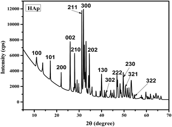 |
| | Fig. 1 XRD pattern of calcined pure HAp. | |
Table 1 Crystallographic results of the synthesized hydroxyapatite (HAp)
| Parameters |
Pure HAp |
| Crystal size (nm) |
55.46 |
| Lattice parameters (Å) |
a = 9.35 = b, c = 6.83 |
| Crystallinity index (CI) |
2.19 |
| Crystallinity degree (Xc) |
3.64 |
| Microstrain (ε) |
0.0023 |
| Dislocation density (δ) |
0.0049 |
| Preference growth (P) |
0.0102 |
The crystallite size (using the Scherrer formula) is calculated as follows:
| |  | (2) |
where
D = crystallite size,
K = shape factor having a value of 0.90,
λ = wavelength,
β = FWHM (full width at half maximum) in radian, and
θ = diffraction angle (in degree).
The lattice parameter equation for hexagonal is as follows:
| |  | (3) |
where
dhkl is the interplanar distance and
a,
b,
c,
h,
k, and
l are the lattice parameters.
The crystallinity degree is calculated using the following equation:
| |  | (4) |
where
Kα is a constant, with a value of 0.24 for most of the HAp and
β is the FWHM (full width at half maximum) in degree.
The crystallinity index is calculated as follows:
| |  | (5) |
where
H = peak heights at the corresponding planes.
The formula for the dislocation density is:
| |  | (6) |
Microstrain is calculated as follows:
| |  | (7) |
where the FWHM (full width at half maximum) is in radian and
θ is the diffraction angle (in degree).
Relative intensity is calculated using the following equation:
| |  | (8) |
Preference growth is calculated as follows:
| |  | (9) |
Determination of functional groups
Fig. 2 illustrates the FTIR spectrum of the composites of epoxy resin reinforced with silica and HAp. The oscillation of the resin ring was attributed to the spectral line seen at 914 cm−1 in the FTIR spectrum.55 Additionally, the vibration of the heterocyclic atoms is responsible for the spectrum at 2912 cm−1. Due to the oscillations caused by the Si–O–Si symmetrical stretching, the Si–OH stretching, and the Si–O–Si asymmetrical stretching, the typical lines for silica were identified at 807 cm−1, 955 cm−1, and 1172 cm−1. Observed water molecules’ O–H bending vibrational technique was determined whenever the source of the peak at 1601 cm−1. The produced CO2 during the application of an intensified comprehensive reflection system is indicated by the peak obtained at 2353 cm−1. The peaks at 625 cm−1, 592 cm−1, and 560 cm−1 are caused by the bending mechanism of the P–O–P group. Comparably, the peaks at 1022 cm−1 and 946 cm−1 are associated with the phosphate stretching band P–O, another main relevant portion for HAp.56,57 Peak locations are given in Table 2.
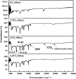 |
| | Fig. 2 FTIR spectrum of HAp and silica-reinforced epoxy resin. | |
Table 2 Peak locations and characteristics of the peaks from the FT-IR spectrum
| Peak locations (cm−1) |
Characteristics |
| 914 |
Oscillation of the resin ring |
| 2912 |
Vibration of the heterocyclic atoms |
| 1601 |
O–H bending vibration |
| 807 |
Si–O–Si symmetrical stretching |
| 955 |
Si–OH stretching |
| 1172 |
Si–O–Si asymmetrical stretching |
| 625, 592, and 560 |
P–O–P group bending mechanism |
| 946 and 1022 |
Phosphate stretching band P–O |
| 2353 |
Naturally occurred CO2 |
Investigation of the mechanical characteristics
The tensile strength (TS), tensile modulus (TM), percentage of elongation at break (% EB), bending strength (BS), and bending modulus (BM) of the prepared composites were analyzed using a universal testing machine, and the data are illustrated in Fig. 3–7. The values for the control sample are 25.6 MPa (TS), 418.25 MPa (TM), 5.75% (EB), 21.3 MPa (BS), and 1470 MPa (BM), which are presented in respective figures. Neat epoxy resin exhibited a higher tensile strength than that of the HAp–epoxy–silica composite, and with the incorporation of reinforcing agents in the matrix, the tensile strength was reduced. The presence of empty areas in the composite materials’ internal structure could have been the reason for the final decline in tensile characteristics (the tensile strength and the tensile modulus). As the silica and HAp particles connected with the epoxy matrix, a particular quantity of vacuum ultimately appeared. The reason for this was that the mixture turned sticky and inert when HAp and silica (SiO2) were combined with epoxy resin and the hardener. Plenty of air pockets seemed to be efficiently formed and locked within the solid composite when the blend was dried up after being agitated with a glass rod.47,48 These materials had inferior tensile characteristics because during further measurement using a UTM machine, the internal holes were unable to bear the stress and could have allowed defects to spread within the entire material. An additional explanation for these reduced tensile attributes could be an ineffective interaction between the matrix-reinforcing and matrix–matrix components. The produced composite materials’ bending strength (BS) and bending modulus (BM) are depicted in Fig. 6 and 7, respectively. The reduced elongation at the break of the composites alters the materials’ plasticity. The bending strength (BS) and the bending modulus (BM) increase with the decreasing plasticity; Fig. 6 and 7 demonstrate that the HAp and silica-reinforced epoxy resin composites have higher bending properties.
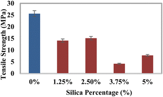 |
| | Fig. 3 Variation of the tensile strength (TS) with the percentages of silica (SiO2). | |
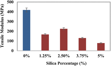 |
| | Fig. 4 Variation of the tensile modulus (TM) with the percentages of silica (SiO2). | |
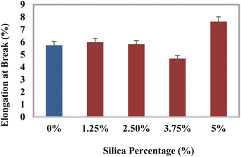 |
| | Fig. 5 Variation of elongation at break (% EB) with the percentages of silica (SiO2). | |
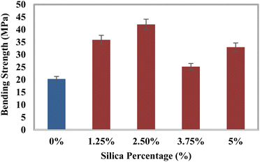 |
| | Fig. 6 Variation of the bending strength (BS) with the percentages of silica (SiO2). | |
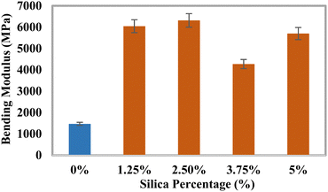 |
| | Fig. 7 Variation of the bending modulus (BM) with the percentages of silica (SiO2). | |
Test for water uptake
The specifics of the water retention percentage of the composite material with the percentages of silica are shown in Fig. 8. The assembled components and the regulating sample were immersed in distilled water to measure the water retention capacity. Immediately following a set period, the percentage of water absorbed was estimated. Three assessments were conducted for each blend, and the overall amounts of all categories were noted. The water uptake data for the epoxy and silica percentages under a standard atmosphere are shown in Fig. 8. According to the previously indicated finding, the blend that received a 1.25% silica processing seemed to have the most retention of water, whilst the untreated sample showed the lowest degree of water absorption. After a period of time, the component's water content climbed to its maximum level in 33 days. The mixtures showed a change in hydration with the silica percentage from 0.44% to 0.75%, which was more than the amount seen in the reference material. The ingredient's vacuum may be increased by the addition of HAp and silica, which could result in a higher absorption of water.58 There hasn’t been much water absorption because epoxy resins are often highly water resistant. Moreover, the HAp–resin–silica combination's epoxy phase growth in proximity to HAp/silica particles displayed some minor water absorption properties. Water intake was increased as a consequence of the water getting trapped in several of the remaining gaps on the matrix and reinforcement borders. The SiO2 molecules are small in size compared to those of the cross-linked resin, and the SiO2 molecules are supposed to fill the gaps inside the vacant place of the matrix materials along with the reinforcing material HAp. The addition of SiO2 with HAp may form layer-separated sections which may induce to pull out the section in the tensile test but contribute to the bending strength. The SEM image also demonstrated layer formation. There may be another effect which is the polarization variation of SiO2 and hydroxyapatite. This may also contribute to the variations in the tensile strength and the bending strength.
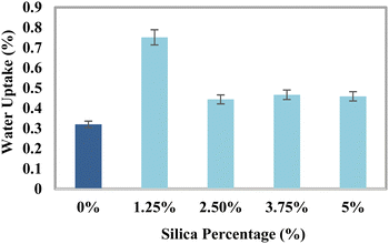 |
| | Fig. 8 Water retention percentage of the composite material with the percentages of silica. | |
Absorption in SBF solution
After adding the SBF, three fractions of the optimally blended specimens (made of 2.5% silica + 50% epoxy resin + 47.5% HAp) were stored at 5 to 10 °C. Following the designated periods of three days, one week, two weeks, three weeks, and four weeks, every single sample was taken out and laid out to dry at ambient humidity for three to four hours. The actual mass of the tested samples shifted slowly with time, as shown in Fig. 9.
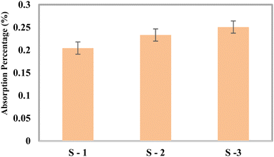 |
| | Fig. 9 Change of weight in the SBF solution. | |
Test for flame retardancy
Every portion of the blend was evaluated for fire resistance capacity, and the findings are displayed in Fig. 10. The composite sample treated with 5% silica had the lowest typical blazing period of 1.48 s, whereas the group with 1.25% silica had the longest blazing duration of 4.44 s. The usual fire time frame decreases with the inclusion of reinforcing chemicals.
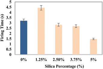 |
| | Fig. 10 Variation of the average firing time with the percentages of silica (SiO2). | |
Density analysis
The density of the produced composites increased with the addition of reinforcing agents since their bulk densities were larger than that of epoxy resin. An increase in the density with the amount of reinforcing agents had been found in other research studies.59,60Fig. 11 illustrates the change in the density in g cm−3 that takes place when silica and HAp are added. The untreated sample has a density of 1.2375 g cm−3, according to the figure. The mix including 5% silica and 45% HAp had the highest density of 1.5192 g cm−3 since it was composed of the highest amount of reinforcing agents. The material's density was facilitated by the addition of powdered components, which enhanced the mass per unit volume. However, the obtained density of the fabricated material was a bit lower compared to its actual density since the composite had vacuum.
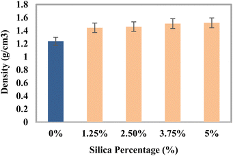 |
| | Fig. 11 Density variation of the composite materials with the percentages of silica. | |
Thermo-gravimetric analysis of the composite materials
Fig. 12 demonstrates the TGA profiles for epoxy resin composites reinforced with silica and HAp. The starting temperature was 26 °C, and the final temperature was 690 °C. For every percentage, two samples were offered for TGA. Composite materials can retain 98.85% of their structural integrity at 280 °C, while the proportion of weight reduction was manageable at temperatures ranging from 340–360 °C. The weight then noticeably drops off whenever it reaches 410–440 °C. It seems once the degree of temperature climbs to about 360–370 °C, the blended samples tend to decrease in weight. An almost identical plot was found in other literature for the epoxy-based composite.61 Moisture may be able to settle within the open pores throughout the contact points of the reinforcing agent and the matrix. At 80–100 °C, moisture starts to escape from the object being examined, and the first instance of a decrease in the weight was due to this moisture evaporation. The total quantity of waste when the blends were broken down was indicated by the fraction of weight loss at 690 °C. Because of the formation of char, epoxy-based composites have a significant quantity of waste. Once the maximal temperature of 690 °C was attained, around 33–43% of the overall mass of the composite portions was still present. Therefore, the behavior of the composite materials within air and nitrogen environments when subjected to high temperatures was ascertained through TGA evaluation.
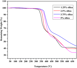 |
| | Fig. 12 Change in the weight of the composite samples with elevated temperature. | |
Temperature effects on the mechanical properties of the composites
The effects of three different temperature scenarios 50 °C, 0 °C, and −50 °C on the mechanical characteristics of the composite materials are displayed in Fig. 13. Before performing the assessment, the optimal content of 2.5% silica (SiO2) was considered into account. By correlating the statistical mechanical response of the materials at low (0 °C, −50 °C) as well as elevated temperatures (50 °C), the impacts of the temperature on the strength of the material were assessed. Before being put onto the inspection body, every single item was initially allowed to reach the conditioned temperature at an appropriate time. The results of the low-temperature influence at −50 °C indicated a rise in the tensile modulus (TM) and elongation at break (% EB). When comparing the tensile strength under the two different temperature circumstances, it was found that the tensile strength climbed to 50 °C. As a result of an increase in the rotational and vibrational oscillation of the components brought due to the shift in temperature, the tensile modulus decreased at increased temperatures.
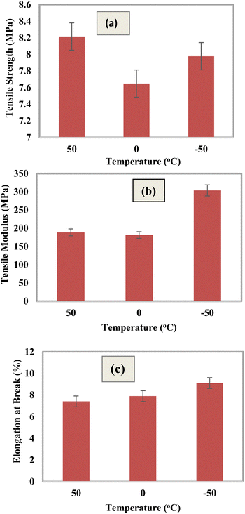 |
| | Fig. 13 Mechanical properties of the composite materials at different temperature regions: (a) tensile strength, (b) tensile modulus, and (c) elongation at break (%). | |
Effects of pH on degradation
Fig. 14 shows how the degradation features of the HAp and silica-loaded epoxy resin composite are affected by acidic and alkaline solutions. Nitric acid (HNO3) and sodium hydroxide (NaOH) were added dropwise to the desired solution to regulate its pH. After 21 days, it was noticed that the composites mostly degraded in acid solution, with a degradation percentage of 0.51%; this could be the consequence of the breakdown of some components from the framework of the composite. Weight development that occurs gradually at neutral and basic conditions may be a sign that the solution has become stuck in gaps between the composites. However, the components in the alkali solution started to break down shortly after three weeks.
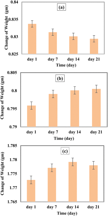 |
| | Fig. 14 Variation of weight at different pH ranges; (a) pH = 3, (b) pH = 7, and (c) pH = 11. | |
SEM analysis
The appearance of the cracked region of the epoxy resin-based composite, which has been illustrated in Fig. 15, can be explained by substantial uneven areas and void spaces in the interface between the reinforcement and the matrix, which are responsible for the material's low strength. Similar results were found in other literature studies for the resin and particle combination.48 The pictures demonstrated that the silica and HAp particles were distributed throughout the epoxy matrix. Fig. 15(c) and (d) demonstrate how the particles weren’t uniformly spread with large percentages of silica loading (5%). The cohesiveness of the silica and HAp particles as well as the epoxy resin's viscosity may have impeded the consistency of distribution at high silica importing levels (5%). It might be inferred to suggest that to achieve a homogenous spreading, the agglomerates could not be fully broken up by the traditional mixing process. Following 2.5% silica and 47.5% HAp loading, Fig. 15(a) and (b) additionally illustrate a certain fault portion, which may be recognized by the significant number of voids on the surface. As a result, it is remarkable to observe how the matrix has thoroughly penetrated the aggregate to split it into less extensive accumulates at minimal loading levels. However, the tiny holes joined to produce an individual prevalent rupture, and when subjected to significant loading levels, microvoid formation caused the material to break down quickly, which is a reason for its poor mechanical attributes.
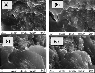 |
| | Fig. 15 SEM micrographs of the fabricated composites; (a and b) 2.5% silica + 47.5% HAp as reinforcement and (c and d) 5% silica + 45% HAp as reinforcement. | |
Comparison of mechanical properties
The composite with 2.5% silica loading has the maximum bending strength (BS) and bending modulus (BM), which are 107.17% and 329.77% more than those of the untreated sample. According to the findings, the fabricated materials could serve as an effective scaffold for load-bearing applications. To demonstrate the development of the bending strength and the bending modulus with various epoxy-based composites, a comparative analysis has been included in Table 3.
Table 3 Comparison of bending properties with the existing literature
| Mechanical properties |
Epoxy−HAp–silica |
Fly ash−epoxy |
Graphene oxide−epoxy |
HAp−epoxy |
HAp−epoxy |
Bovine bone-derived HAp−epoxy |
Snail shell derived HAp−epoxy |
Carbon fiber-HAp−epoxy |
Fishbone powder−epoxy |
| Bending Strength (MPa) |
35.92–42.05 |
81.64–110.49 |
60.25–113.07 |
30–38 |
20.53–43.04 |
82.49–84.51 |
41.40–63.95 |
25–34.8 |
22–35 |
| Bending Modulus (MPa) |
4275.06–6317.63 |
— |
2800–3300 |
500–2200 |
603.61–943.59 |
2260.31–2268.54 |
561.1–774.6 |
— |
553–800 |
| Ref. |
This work |
62
|
63
|
64
|
65
|
66
|
67
|
68
|
69
|
Conclusion
The development of a HAp and silica-reinforced epoxy composite for biomedical purposes was demonstrated in this study. The produced composites were shown to have better mechanical and thermal stabilities, water uptake, and SBF absorption capabilities based on the findings. These findings demonstrated that silica and HAp-loaded epoxy resin composites can be appropriately employed in biomedical settings. The ideal combination exhibited improvements of 107.17% and 329.77% in both BS and BM, respectively, compared to the controlled example. On the other hand, the reason for the slight absorption of SBF and water is the voids that can be seen in SEM pictures. SEM pictures and the FTIR spectrum did not provide any kind of data on the chemical bonding.
Author contributions
Md. Kawcher Alam fabricated and characterized the hydroxyapatite-based composites, analysed the data, and wrote the draft and the original manuscript. Md. Sahadat Hossain conceived and designed the experiment and analysed the data. Newaz Mohammed Bahadur and Samina Ahmed supervised the findings of this work. Samina Ahmed supervised the overall work and managed the required facilities.
Data availability
Data will be made available on request.
Conflicts of interest
There are no conflicts to declare.
Acknowledgements
The authors are grateful to the Bangladesh Council of Scientific and Industrial Research (BCSIR) authority for financial support through R&D projects (ref. no. 39.02.0000.011.14.134.2021/900; date: 30.12.2021) and (ref. no. 39.02.0000.011.14.157.2022/172; date: 10.11.2022). Md. Kawcher Alam is thankful to the Department of Applied Chemistry and Chemical Engineering, Noakhali Science and Technology University, Noakhali, Bangladesh for approving the M.S. Thesis program.
References
- N. Mamidi, R. G. García, J. D. H. Martínez, C. M. Briones, A. M. Martínez Ramos, M. F. L. Tamez, B. G. Del Valle and F. J. M. Segura, ACS Biomater. Sci. Eng., 2022, 8, 3690–3716 CrossRef CAS PubMed.
- H. M. Khan, X. Liao, B. A. Sheikh, Y. Wang, Z. Su, C. Guo, Z. Li, C. Zhou, Y. Cen and Q. Kong, J. Mater. Chem. B, 2022, 10, 6859–6895 RSC.
- H. Wang, Polymers, 2023, 15, 847 CrossRef CAS PubMed.
- H. Qu, H. Fu, Z. Han and Y. Sun, RSC Adv., 2019, 9, 26252–26262 RSC.
- S. Bhat, U. T. Uthappa, T. Altalhi, H.-Y. Jung and M. D. Kurkuri, ACS Biomater. Sci. Eng., 2022, 8, 4039–4076 CrossRef CAS PubMed.
- P. C. Pires, F. Mascarenhas-Melo, K. Pedrosa, D. Lopes, J. Lopes, A. Macário-Soares, D. Peixoto, P. S. Giram, F. Veiga and A. C. Paiva-Santos, Eur. Polym. J., 2023, 111868 CrossRef CAS.
- K. Vdoviaková, A. Jenca, A. Jenca Jr, J. Danko, L. Kresáková, V. Simaiová, P. Reichel, P. Rusnák, J. Pribula and M. Vrzgula, Biomedicines, 2023, 11, 877 CrossRef PubMed.
- T. S. Carvalho, N. Ribeiro, P. M. Torres, J. C. Almeida, J. H. Belo, J. P. Araújo, A. Ramos, M. Oliveira and S. M. Olhero, Mater. Chem. Phys., 2023, 296, 127175 CrossRef CAS.
-
A. Gopanna, K. P. Rajan, S. P. Thomas and M. Chavali, in Materials for biomedical engineering, Elsevier, 2019, pp. 175–216 Search PubMed.
- M. I. Ul Haq, Russ. J. Appl. Chem., 2007, 80, 1256–1269 CrossRef CAS.
- M. Zare, E. R. Ghomi, P. D. Venkatraman and S. Ramakrishna, J. Appl. Polym. Sci., 2021, 138, 50969 CrossRef CAS.
- C. Li, H. Dong and W. Zhang, Surf. Eng., 2018, 34, 870–876 CrossRef CAS.
- G. G. Silva, M. L. da Costa Valente, L. Bachmann and A. C. Dos Reis, Mater. Sci. Eng., C, 2019, 99, 1341–1349 CrossRef PubMed.
-
M. R. Jorgensen, H. Räägel and T. S. Rollins, in Biopolymers for Biomedical and Biotechnological Applications, eds. B. Rehm and M. F. Moradali, Wiley, 1st edn, 2021, pp. 1–17 Search PubMed.
- M. Bernard, E. Jubeli, M. D. Pungente and N. Yagoubi, Biomater. Sci., 2018, 6, 2025–2053 RSC.
- L. Reeve and P. Baldrick, Expert Rev. Med. Devices, 2017, 14, 161–167 CrossRef CAS PubMed.
- M. Rahimi, G. Charmi, K. Matyjaszewski, X. Banquy and J. Pietrasik, Acta Biomater., 2021, 123, 31–50 CrossRef CAS PubMed.
- J. I. Kang and K. M. Park, J. Mater. Chem. B, 2021, 9, 1503–1520 RSC.
- M. G. Mohamed, A. F. EL-Mahdy, M. G. Kotp and S.-W. Kuo, Mater. Adv., 2022, 3, 707–733 RSC.
- A. Basanth, N. Mayilswamy and B. Kandasubramanian, Polym.-Plast. Technol. Mater., 2022, 61, 816–845 CAS.
- S. Thadepalli, Mater. Today: Proc., 2022, 55, 330–336 CAS.
-
R. Ibrahim, A. Nyska and Y. Ramot, in Biomaterials and Biopolymers, eds. A. Domb, B. Mizrahi and S. Farah, Springer International Publishing, Cham, 2023, vol. 7, pp. 235–253 Search PubMed.
-
A. Sanli, C. Elibol and A. Aydınoğlu, Handbook of Polymers in Medicine, Elsevier, 2023, pp. 87–142 Search PubMed.
- S. Ramakrishna, J. Mayer, E. Wintermantel and K. W. Leong, Compos. Sci. Technol., 2001, 61, 1189–1224 CrossRef CAS.
- S. P. Soundarya, V. Sanjay, A. H. Menon, S. Dhivya and N. Selvamurugan, Int. J. Biol. Macromol., 2018, 110, 74–87 CrossRef PubMed.
- J. E. Song, N. Tripathy, D. H. Lee, J. H. Park and G. Khang, ACS Appl. Mater. Interfaces, 2018, 10, 32955–32964 CrossRef CAS PubMed.
- L. Fertier, H. Koleilat, M. Stemmelen, O. Giani, C. Joly-Duhamel, V. Lapinte and J.-J. Robin, Prog. Polym. Sci., 2013, 38, 932–962 CrossRef CAS.
- A. A. K. Gorar, G. Zhiyi, W. Zhicheng, A. Daham, Z. Pan, J. Wang, W.-B. Liu and M. Derradji, J. Appl. Polym. Sci., 2023, 140, e54646 CrossRef CAS.
- M. Derradji, O. Mehelli, W. Liu and N. Fantuzzi, Front. Chem., 2021, 9, 691117 CrossRef CAS PubMed.
- F. A. M. M. Gonçalves, M. Santos, T. Cernadas, P. Alves and P. Ferreira, J. Mater. Sci., 2022, 57, 15183–15212 CrossRef.
- H. Alshahrani and V. R. A. Prakash, Biomass Convers. Biorefin., 2024, 14, 8081–8089 CrossRef CAS.
- K. Devendra and K. R. Vishnu, Mater. Today: Proc., 2022, 66, 1664–1670 Search PubMed.
- Z. F. Merzah, S. Fakhry, T. G. Allami, N. Y. Yuhana and A. Alamiery, Polymers, 2022, 14, 526 CrossRef CAS PubMed.
-
G. Zambelis, H.-M. Enginsoy, E. Bayraktar, A. Larbi and D. Katundi, in Mechanics of Composite, Hybrid and Multifunctional Materials, Fracture, Fatigue, Failure and Damage Evolution, eds. V. Chalivendra, A. M. Beese and R. B. Berke, Springer International Publishing, Cham, 2022, vol. 3, pp. 55–63 Search PubMed.
- F.-L. Jin, X. Li and S.-J. Park, J. Ind. Eng. Chem., 2015, 29, 1–11 CrossRef CAS.
-
S. Bobby and M. A. Samad, Materials for Biomedical Engineering, Elsevier, 2019, pp. 145–174 Search PubMed.
- S. Dutta, N. Karak, J. P. Saikia and B. K. Konwar, Bioresour. Technol., 2009, 100, 6391–6397 CrossRef CAS PubMed.
- S. Barua, N. Dutta, S. Karmakar, P. Chattopadhyay, L. Aidew, A. Buragohain and N. Karak, Biomed. Mater., 2014, 9, 025006 CrossRef CAS PubMed.
- Q. Chen, Z. Jiang, X. Pei, Y. Liu, R. Du and G. Zhao, Compos. Sci. Technol., 2021, 207, 108739 CrossRef CAS.
- S. Barua, P. Chattopadhyay, L. Aidew, A. K. Buragohain and N. Karak, Polym. Int., 2015, 64, 303–311 CrossRef CAS.
- D. Puglia, H. J. Maria, J. M. Kenny and S. Thomas, RSC Adv., 2013, 3, 24634–24643 RSC.
- L. Ranakoti, B. Gangil, P. K. Rajesh, T. Singh, S. Sharma, C. Li, R. A. Ilyas and O. Mahmoud, J. Mater. Res. Technol., 2022, 19, 2863–2876 CrossRef CAS.
- I. O. Oladele and B. A. Isola, J. Appl. Biotechnol. Bioeng., 2016, 1, 66 Search PubMed.
- J. Kong, R. Ning and Y. Tang, J. Mater. Sci., 2006, 41, 1639–1641 CrossRef CAS.
- M. Kawsar, M. S. Hossain, M. K. Alam, N. M. Bahadur, M. A. A. Shaikh and S. Ahmed, J. Mater. Chem. B, 2024, 12, 3376–3391 RSC.
- M. K. Alam, M. S. Hossain, M. Kawsar, N. M. Bahadur and S. Ahmed, RSC Adv., 2024, 14, 3548–3559 RSC.
- M. F. Ali, M. S. Hossain, T. S. Moin, S. Ahmed and A. S. Chowdhury, Nano Hybrids Compos., 2021, 32, 73–84 Search PubMed.
- M. F. Ali, M. A. Ahmed, M. S. Hossain, S. Ahmed and A. S. Chowdhury, Compos., Part C: Open Access, 2022, 9, 100320 CAS.
- D. S. Couto, N. M. Alves and J. F. Mano, J. Nanosci. Nanotechnol., 2009, 9, 1741–1748 CrossRef CAS PubMed.
- P. Siriphannon, S. Hayashi, A. Yasumori and K. Okada, J. Mater. Res., 1999, 14, 529–536 CrossRef CAS.
- M. S. Hossain, M. N. Uddin, S. Sarkar and S. Ahmed, J. Saudi Chem. Soc., 2022, 26, 101559 CrossRef CAS.
- M. S. Hossain, S. M. Tuntun, N. M. Bahadur and S. Ahmed, RSC Adv., 2022, 12, 34080–34094 RSC.
- Md Sahadat Hossain and S. Ahmed, J. Saudi Chem. Soc., 2023, 27, 101649 CrossRef CAS.
- M. K. Alam, M. S. Hossain, N. M. Bahadur and S. Ahmed, J. Mol. Struct., 2024, 137820 CrossRef CAS.
- E. Sahmetlioglu, H. Mart, H. Yuruk and Y. Sürme, Chem. Pap., 2006, 60, 65–68 CAS.
- K. P. Tank, P. Sharma, D. K. Kanchan and M. J. Joshi, Cryst. Res. Technol., 2011, 46, 1309–1316 CrossRef CAS.
- H. Kim, S. Mondal, B. Jang, P. Manivasagan, M. S. Moorthy and J. Oh, Ceram. Int., 2018, 44, 20490–20500 CrossRef CAS.
- Z. S. Al-khafaji, N. S. Radhi and S. A. Mohson, Int. J. Mech. Eng. Technol., 2018, 9, 468–478 Search PubMed.
- S. Chakraborty, S. P. Kundu, A. Roy, B. Adhikari and S. B. Majumder, Constr. Build. Mater., 2013, 49, 214–222 CrossRef CAS.
- S. Choi, B. Park and H. Song, Polym. Adv. Technol, 2004, 15, 122–127 CrossRef CAS.
- M. A. Hossain, M. S. Hossain, R. A. Khan and A. S. Chowdhury, Adv. Appl. Sci., 2022, 7, 65 Search PubMed.
-
S. P. Reddy, P. C. S. Rao, A. C. Reddy and G. Parmeswari, International Conference on Advanced Materials and Manufacturing Technologies (AMMT), 2014 Search PubMed.
- J. Tang, H. Zhou, Y. Liang, X. Shi, X. Yang and J. Zhang, J. Nanomater., 2014, 2014, e696859 Search PubMed.
- I. O. Oladele, O. S. Akinola, O. G. Agbabiaka and J. A. Omotoyinbo, Fibers Polym., 2018, 19, 452–459 CrossRef CAS.
- I. O. Oladele, L. Onuh, A. S. Taiwo, S. Borisade, N. I. Agbeboh and S. S. Lephuthing, Int. J. Sustainable Eng., 2022, 15, 122–135 CrossRef.
- A. F. Jaramillo, C. Medina, P. Flores, C. Canales, C. Maldonado, P. Castaño Rivera, D. Rojas and M. F. Meléndrez, Ceram. Int., 2020, 46, 8368–8378 CrossRef CAS.
- I. O. Oladele, A. S. Taiwo, L. N. Onuh, S. O. Adelani, S. O. Balogun, S. S. Lephuthing and P. A. Olubambi, Compos. Adv. Mater., 2023, 32, 26349833231223984 Search PubMed.
- İ. F. M. Aljewari, E. Koç and Y. Akgül, Bilecik Şeyh Edebali Üniv. Fen Bilim. Derg., 2024, 11, 183–194 CrossRef.
- F. Hani, A. Firouzi, M. R. Islam and M. G. Sumdani, Polym. Compos., 2021, 42, 1224–1234 CrossRef CAS.
|
| This journal is © The Royal Society of Chemistry 2024 |
Click here to see how this site uses Cookies. View our privacy policy here.  Open Access Article
 a,
Newaz Mohammed
Bahadur
b and
Samina
Ahmed
 *a
*a


