 Open Access Article
Attaining improved cycling durability and engineering a dendrite-free lithium metal anode
Hyeong-Seok
Oh†
a,
Rae-Hyun
Lee†
a,
Jong-Kyu
Lee
a,
Jung-Rag
Yoon
*b,
Hyun-Kyung
Kim
*a and
Seung-Hwan
Lee
 *a
*a
aDepartment of Battery Convergence Engineering, Kangwon National University, Chuncheon 24341, Republic of Korea. E-mail: shlee@kangwon.ac.kr
bR&D Center, Samwha Capacitor, Yongin, 449-884, Korea
First published on 26th September 2024
Abstract
The development of Li metal batteries with increased lifespan and energy density is crucial for next-generation energy storage systems. To achieve this, it is necessary to control the growth of Li dendrites, which can lead to cycling performance issues and safety concerns. One approach to increase the energy density of large-scale Li metal-based batteries is to use thin Li metal anodes. However, fabricating thin Li metal anodes from natural oxide layers can be difficult. In this study, we used pure Li metal powder to fabricate thin Li metal anodes, which do not possess a natural oxide layer. This resulted in Li plating with a low overpotential on the unprotected Li metal surface. Our fabricated LiMP symmetric cell maintained stable cycling for over 170 hours at a current density of 1.0 mA cm−2, demonstrating superior performance compared to bare Li metal foil. Furthermore, we evaluated the performance of an all-solid-state battery (ASSB) using a polymer solid electrolyte and an oxide-based solid electrolyte in the fabricated LiMP symmetric cell. At 0.1 mA cm−2, the conventional Li symmetric cell experienced polarization after 200 hours, while the LiMP symmetric cell remained stable even after 600 hours. Taken together, these results provide new insights into the development of high-performance Li metal batteries.
1. Introduction
The growing market for electric vehicles and energy storage systems (ESSs) has fueled the increasing demand for batteries with high energy density.1–5 Currently, conventional graphite anode materials have a specific capacity limited to 372 mA h g−1, prompting ongoing research into alternative anode materials.6 Li metal has attracted significant attention due to its notably high specific capacity of 3800 mA h g−1 and low operating voltage.7 Although the Li metal is an ideal anode material, its inherent dendrite formation and high chemical reactivity lead to uncontrolled interfacial reactions with the electrolyte.8 The Li metal is susceptible to dendrite growth due to the presence of inorganic materials such as Li2O, LiOH, and Li2CO3 covering its surface.9,10 The physical and chemical heterogeneity of these materials causes an uneven distribution of surface currents, consequently leading to uncontrolled Li deposition after plating.11,12 This phenomenon increases the risk factors such as explosiveness, flammability, and safety hazards of the Li metal. This leads to considerable changes on its surface, exposing fresh portions of the metal to the electrolyte.13Various approaches are being explored to suppress uncontrolled Li metal plating: (1) controlling the thickness of the Li metal anode,14 (2) interfacial engineering involving a protective layer for the Li metal,15 and (3) adopting hierarchical host materials.16 Despite these efforts, research on Li metal anodes has been carried out for addressing the market demands for high-energy density and large-capacity batteries. Herein, we propose a method utilizing Li metal powder (LiMP) to reduce the thickness and control inorganic substances on the surface. The fabrication of a LiMP electrode via slurry casting enables thickness control and facilitates the development of an anode devoid of the aforementioned inorganic materials.14
Moreover, ASSBs, a promising candidate for next-generation energy storage, offer improved safety compared to conventional LIBs with flammable organic electrolytes. ASSBs significantly contribute to inhibiting the growth of Li dendrites, potentially enhancing safety measures and energy density.17 Solid electrolytes can be broadly classified into three categories: polymer electrolytes, inorganic ceramic electrolytes, and composite solid electrolytes (CSEs). Polymer electrolytes consist of a polymer matrix mixed with lithium salts, which results in excellent processability, flexibility, safety performance, and superior interfacial contact with the electrodes. However, they exhibit a low ionic conductivity (<10−4 S cm−1) and poor thermal and electrochemical properties. On the other hand, inorganic ceramic electrolytes demonstrate a higher ionic conductivity (10−3–10−2 S cm−1) and greater mechanical strength, but their interfacial contact with electrodes is not as efficient.18,19 Consequently, CSEs, which combine the advantages of both types, including high ionic conductivity, excellent flexibility, and close contact with electrodes, are considered to be one of the most promising electrolyte options.20,21
This synthesis of polymer and inorganic ceramic electrolytes with unique properties into CSEs highlights the potential for achieving an optimal balance of ionic conductivity, mechanical strength, and interfacial compatibility. As such, CSEs are viewed as a vital advancement in the development of ASSB technology, offering a pathway to safer, more reliable, and higher-performing energy storage solutions.22,23 We fabricated cells using diverse solid electrolytes in conjunction with our LiMP electrode and achieved improved electrochemical performance compared to that of traditional Li metal films. Our study offers strategies for enhancing the performance of next-generation Li metal batteries.
2. Experimental
2.1 Fabrication of the LiMP electrode
LiMP (NEBA Corporation, Korea) was used as the anode material. A liquid electrolyte comprising 1 molar Li hexafluorophosphate (LiPF6) containing EC![[thin space (1/6-em)]](https://www.rsc.org/images/entities/char_2009.gif) :
:![[thin space (1/6-em)]](https://www.rsc.org/images/entities/char_2009.gif) DMC
DMC![[thin space (1/6-em)]](https://www.rsc.org/images/entities/char_2009.gif) :
:![[thin space (1/6-em)]](https://www.rsc.org/images/entities/char_2009.gif) EMC at a ratio of 1
EMC at a ratio of 1![[thin space (1/6-em)]](https://www.rsc.org/images/entities/char_2009.gif) :
:![[thin space (1/6-em)]](https://www.rsc.org/images/entities/char_2009.gif) 1
1![[thin space (1/6-em)]](https://www.rsc.org/images/entities/char_2009.gif) :
:![[thin space (1/6-em)]](https://www.rsc.org/images/entities/char_2009.gif) 1 (Enchem, Korea) was employed. Microporous polyethylene (PE; Asahi Kasei E-materials, Japan) was utilized as the separator. A composite solid electrolyte (CSE) was crafted using polyvinylidene fluoride-hexafluoropropylene (PVDF-HFP) (Sigma Aldrich, USA)/Li bis(trifluoromethanesulfonyl)imide (LiTFSI) (Sigma Aldrich, USA)/succinonitrile (SN, Sigma Aldrich, USA)/LATP (POSCO, Korea), and LATP (POSCO, Korea) was employed to fabricate a LATP film. The LiMP anode was fabricated in an Ar atmosphere glove box. A nonaqueous NMP-based slurry comprising 90 wt% LiMP (NEBA Corporation, Korea) and 10 wt% PVDF-HFP (Sigma Aldrich, USA) was mixed using a vortex mixer (Korea Ace Scientific, Korea) for 1 minute. The slurry was cast onto Cu foil (Iljin Materials, Korea) and dried at 60 °C for 3 hours. The fabrication process of the LiMP electrode is illustrated in Fig. 1.
1 (Enchem, Korea) was employed. Microporous polyethylene (PE; Asahi Kasei E-materials, Japan) was utilized as the separator. A composite solid electrolyte (CSE) was crafted using polyvinylidene fluoride-hexafluoropropylene (PVDF-HFP) (Sigma Aldrich, USA)/Li bis(trifluoromethanesulfonyl)imide (LiTFSI) (Sigma Aldrich, USA)/succinonitrile (SN, Sigma Aldrich, USA)/LATP (POSCO, Korea), and LATP (POSCO, Korea) was employed to fabricate a LATP film. The LiMP anode was fabricated in an Ar atmosphere glove box. A nonaqueous NMP-based slurry comprising 90 wt% LiMP (NEBA Corporation, Korea) and 10 wt% PVDF-HFP (Sigma Aldrich, USA) was mixed using a vortex mixer (Korea Ace Scientific, Korea) for 1 minute. The slurry was cast onto Cu foil (Iljin Materials, Korea) and dried at 60 °C for 3 hours. The fabrication process of the LiMP electrode is illustrated in Fig. 1.
2.2 Electrochemical analysis
To evaluate the electrochemical performance, symmetric 2032 coin cells were assembled using the Li metal (diameter = 15 mm; NEBA Corporation, Korea) or LiMP (diameter = 15 mm; NEBA Corporation, Korea) in an Ar atmosphere glove box. To assemble the coin cell, we applied an external pressure of 9.8 MPa (100 kg cm−2) using a coin cell assembler (TMAX-JK-KF20-TC). Li metal and LiMP were characterized using field emission FE-SEM (JSM-7900F, JEOL, Japan). An X-ray photoelectron spectrometer (XPS, K Alpha+, Thermo VG, UK) utilizing a monochromatic Al Kα source (1486.6 eV) was employed to analyze the materials. The sample preparation for XPS analysis was conducted in an Ar atmosphere, though exposure to impurities on the metal surface was unavoidable. The final LiMP electrode had a thickness of 20 μm with a loading level of 3.7 mA h cm−2 and 0.961 mg cm−2. Li plating and stripping experiments were conducted on LiMP symmetric cells at a current density of 0.5 mA cm−2. Each cycle consisted of 30 minutes of plating and 30 minutes of stripping. The full-cell cycling procedure comprised a single formation cycle followed by three pre-cycling sessions. All cycles were performed within a voltage window of 2.7–4.3V. The formation phase involved constant current (CC) charging and discharging at 0.1C, followed by main charge–discharge cycles at 0.2C in CC. The cycling performance of each cell unit was evaluated at 25 °C using a battery testing system (Neware, China). The AC impedance of each cell was measured using an impedance analyzer (VSP, Bio-Logic SAS, France) within a frequency range of 7 MHz to 1 Hz. The potential difference mode was determined at a voltage amplitude of 10 mV. Following electrochemical investigations, the cells were cautiously disassembled in an Ar-filled glove box. The Li samples were gently washed multiple times with dimethyl carbonate and thoroughly dried under vacuum overnight. Subsequently, the samples were analyzed using field emission FE-SEM (JSM-7900F, JEOL, Japan) to perform cross-sectional scanning electron microscopy (SEM) analysis.3. Results and discussion
In Fig. 2, field Emission Scanning Electron Microscopy (FE-SEM) images illustrate the bare Li foil and LiMP electrodes with different levels of compression. While the Li metal foil generally has a natural Li oxide layer, the pure LiMP electrode does not have an oxide layer such as Li2CO3 and Li2O.24,25 Additionally, the electrode manufacturing processes, such as slurry coating and drying, demonstrate that they do not change the structure of the Li powder. Fig. 2a exhibits a smooth surface image of the bare Li foil. Fig. 2b and c display the two LiMP electrodes with different compression levels of 10% and 20%, respectively. As shown in Fig. 2b, the LiMP electrode with 10% compression exhibits a relatively high porous structure with poor particle bonding, which reduces the Li+ diffusion kinetics. In contrast, the LiMP electrode with 20% compression reveals a flat and dense structure similar to a typical polycrystalline configuration with discernible particle boundaries (see Fig. 2b). Consequently, only the electrodes subjected to 20% pressure were utilized in all subsequent experiments. | ||
| Fig. 2 FE-SEM surface images of (a) bare Li foil, (b) 10% pressed LiMP electrode, and (c) 10% pressed LiMP electrode. | ||
In previous research, utilizing the Li metal powder in the electrode resulted in decreased nucleation energy, thereby promoting uniform Li deposition. When a surface passivation layer is present, the feasibility of epitaxial Li deposition diminishes, encouraging dendritic Li deposition.24 Therefore, the reactivity of the exposed Li surface plays a crucial role in determining the morphology and charge–discharge reversibility of the Li deposition material. To validate this understanding, Fig. 3 compares the cycling performance of bare Li and LiMP using a symmetric cell configuration. The charging and discharging processes were conducted for 30 minutes each, at current densities of 0.5 mA cm−2 (Fig. 3a) and 1 mA cm−2 (Fig. 3b), respectively. Comparing the bare Li metal foil and the LiMP electrode, both samples exhibit a stable long-term cycling performance, indicating the absence of dendritic Li at a low current density of 0.5 mA cm−2 over 600 h (see Fig. 3a). When the current density is up to 1.0 mA cm−2, the bare Li metal foil shows an unstable voltage profile with severe polarization at approximately 450 h, while the LiMP electrode still displays stable voltage profile even at high current density (see Fig. 3b). Notably, a high current density is commonly associated with the formation of dendritic and mossy Li, indicating a variation in the morphological characteristics of the Li metal. Hence, the bare Li metal foil exhibits poor cycling performance, unlike the LiMP electrode. This phenomenon reveals that the LiMP electrode exhibits high resistance for Li dendrite formation as well as exhibits a smooth and uniform surface morphology even under high current densities.
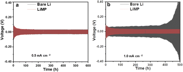 | ||
| Fig. 3 Galvanostatic cycling results at current densities of (a) 0.5 mA cm−2 and (b) 1 mA cm−2 in the Li symmetric cell configuration using a liquid electrolyte. | ||
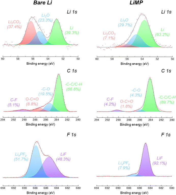
Using X-ray photoelectron spectroscopy (XPS), the surface chemical composition of the bare Li foil and LiMP anode electrodes after the formation cycle was analyzed, as shown in Fig. 4. The specific ratios of peak areas are summarized in Table 1. For both the bare Li foil and LiMP, the inherent surface layer consisting of Li2CO3 and Li2O is detected at 54.2 eV and 53.8 eV in the Li 1s spectrum, respectively (see Fig. 4).26,27 The bare lithium foil exhibits a significant presence of impurities, including Li2CO3 and Li2O, which constitute 37.4% and 23.3% of the total component, respectively, indicating the formation of a surface passivation layer. On the other hand, LiMP shows relatively small amounts of Li2CO3 (7.1%) and Li2O (29.7%). In the C 1s spectra, both the bare Li foil and LiMP indicate a high content of –C–C/–C–H species associated with the carbonate solvent. Additionally, the low content of surface-adsorbed carbon species is assigned to C–F, O–C![[double bond, length as m-dash]](https://www.rsc.org/images/entities/char_e001.gif) O, and –C–O, respectively. In the F 1s spectra, the chemical species of LixPFy and LiF are observed in both samples. LiMP shows relatively high LiF (92.1%) and small LixPFy (7.9%) contents compared to bare Li foil. To the best of our knowledge, LiF compounds act as positive passivation layers to promote fast Li+ diffusion in the SEI (solid electrolyte interface) layer. Therefore, we assume that LiMP demonstrates enhanced cycling stability compared to the bare Li foil. In the case of the bare Li foil, a considerable amount of LixPFy species is detected. This phenomenon indicates that an additional SEI layer is generated by electrolyte decomposition during the formation process.
O, and –C–O, respectively. In the F 1s spectra, the chemical species of LixPFy and LiF are observed in both samples. LiMP shows relatively high LiF (92.1%) and small LixPFy (7.9%) contents compared to bare Li foil. To the best of our knowledge, LiF compounds act as positive passivation layers to promote fast Li+ diffusion in the SEI (solid electrolyte interface) layer. Therefore, we assume that LiMP demonstrates enhanced cycling stability compared to the bare Li foil. In the case of the bare Li foil, a considerable amount of LixPFy species is detected. This phenomenon indicates that an additional SEI layer is generated by electrolyte decomposition during the formation process.
| Spectra | Chemical species | Peak area ratio (%) | |
|---|---|---|---|
| Bare Li | LiMP | ||
| Li 1s | Li2CO3 | 37.4 | 7.1 |
| Li2O | 23.3 | 29.7 | |
| Li | 39.3 | 63.2 | |
| C 1s | C–F | 5.1 | 4.2 |
O–C![[double bond, length as m-dash]](https://www.rsc.org/images/entities/char_e001.gif) O O |
8.8 | 1.8 | |
| –C–O | 19.5 | 4.3 | |
| –C–C/C–H | 66.6 | 89.7 | |
| F 1s | LixPFy | 51.7 | 7.9 |
| LiF | 48.3 | 92.1 | |
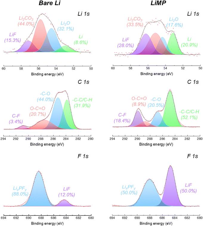
To evaluate the influence of LiMP on the chemical structural changes in the SEI formation process, we conducted a surface chemistry analysis after cycling, as shown in Fig. 5. The detailed ratios of the peak areas are presented in Table 2. In the Li 1s spectrum of the bare Li foil, the peak area ratio of the Li element decreases significantly from 39.3% to 8.6% as the impurity phase (e.g., Li2CO3 and Li2O) increases during galvanostatic cycling. This phenomenon signifies the formation of dead Li and its by-products during plating/stripping. Compared to bare Li foil, LiMP exhibited a smaller increase in the impurity content and a significant 28% increase in the LiF content. As a result, the continuous thickening of the SEI layer was inhibited by the LiF layer, allowing the pure Li content to remain relatively high at 20%. In the C 1s spectrum, after cycling, the chemical species, carboxylate (O–C![[double bond, length as m-dash]](https://www.rsc.org/images/entities/char_e001.gif) O) and polymeric ether (–C–O), are formed as by-products of the electrolyte decomposition process.28 In the case of LiMP, notably lower contents of carboxylate (8.9%) and polymeric ether (20.5%) were observed than the bare Li foil carboxylate (20.7%) and polymeric ether (44.0%). Unlike the organic-rich composition of the bare Li foil after cycling, the LiMP electrode demonstrates a relatively large amount of inorganic LiF constituents within the SEI layer.29,30 The LiF component is generated by the decomposition of the Li salt (e.g., LiPF6) in a liquid electrolyte. Notably, LiF exhibits a positive effect in suppressing the continuous decomposition of the artificial SEI layer. While the bare Li foil indicates a dominant portion of LixPFy (88.0%), LiMP shows a well-balanced SEI layer with LixPFy (50.0%) and LiPF6 (50.0%) through a high-quality pre-passivation layer. Therefore, the superior cycling performance of the LiMP electrode without polarization behavior is also demonstrated by the existence presence of the LiF component.29,30
O) and polymeric ether (–C–O), are formed as by-products of the electrolyte decomposition process.28 In the case of LiMP, notably lower contents of carboxylate (8.9%) and polymeric ether (20.5%) were observed than the bare Li foil carboxylate (20.7%) and polymeric ether (44.0%). Unlike the organic-rich composition of the bare Li foil after cycling, the LiMP electrode demonstrates a relatively large amount of inorganic LiF constituents within the SEI layer.29,30 The LiF component is generated by the decomposition of the Li salt (e.g., LiPF6) in a liquid electrolyte. Notably, LiF exhibits a positive effect in suppressing the continuous decomposition of the artificial SEI layer. While the bare Li foil indicates a dominant portion of LixPFy (88.0%), LiMP shows a well-balanced SEI layer with LixPFy (50.0%) and LiPF6 (50.0%) through a high-quality pre-passivation layer. Therefore, the superior cycling performance of the LiMP electrode without polarization behavior is also demonstrated by the existence presence of the LiF component.29,30
| Spectra | Chemical species | Peak area ratio (%) | |
|---|---|---|---|
| Bare Li | LiMP | ||
| Li 1s | LiF | 15.3 | 28.0 |
| Li2CO3 | 44.0 | 33.5 | |
| Li2O | 32.1 | 17.6 | |
| Li | 8.6 | 20.9 | |
| C 1s | C–F | 3.4 | 18.4 |
O–C![[double bond, length as m-dash]](https://www.rsc.org/images/entities/char_e001.gif) O O |
20.7 | 8.9 | |
| –C–O | 44.0 | 20.5 | |
| –C–C/C–H | 31.9 | 52.1 | |
| F 1s | LixPFy | 88.0 | 50.0 |
| LiF | 12.0 | 50.0 | |
The morphological characteristics of the bare Li foil and LiMP electrode following precycling are depicted in Fig. 6a and b. These precycling tests were conducted utilizing a symmetric cell configuration. The bare Li foil and LiMP electrode exhibit ruptured structures. In particular, bare Li foils not only display large amounts of dendritic Li but also experience more severe irreversible Li loss compared to LiMP electrodes. This is due to the presence of impurities (Li2CO3 and Li2O) on the surface of the bare Li foil,31 which obstruct Li+ transport due to its low ionic conductivity.24 As a result, the plated Li is not completely reversible, leading to the formation of mossy dendrites and dead Li on the surface of bare Li foil.12 As shown in Fig. 6b, although the LiMP electrode exhibits dendritic features, it demonstrates a stable surface morphology compared to the bare Li foil.32 Hence, the formation of Li dendrites in Li metal electrodes is strongly related to the surface impurities. From the aforementioned XPS analysis, the LiMP electrode was confirmed to have a relatively small amount of impurities. The surface images of the bare Li and LiMP electrode after cycling are presented in Fig. 6b and c. To the best of our knowledge, utilizing the Li metal powder in the electrode results in decreased nucleation energy, thereby promoting uniform Li deposition. When a surface passivation layer is present, the feasibility of epitaxial Li deposition diminishes, encouraging dendritic Li deposition.33 Therefore, the reactivity of the exposed Li surface plays a crucial role in determining the morphology and charge–discharge reversibility of the Li deposition material.33 To validate this understanding, we present the FE-SEM images of electrodes after conducting the charging and discharging processes for 30 minutes each at a current density of 1.0 mA cm−2. In the case of the bare Li foil, the surface SEM image shows the formation of cracks and uneven deposition of Li, indicating a variation in the morphological characteristics of the electrode. On the other hand, the LiMP electrode also reveals the void space and formation of Li dendrites but exhibits a relatively smooth surface structure due to the effect of the LiF protective layer, which effectively alleviates the propagation of dendritic Li and side reactions. Taken together, the LiMP electrode shows high electrochemical stability due to the low surface impurities and the formation of a stable, protective film layer after cycling.
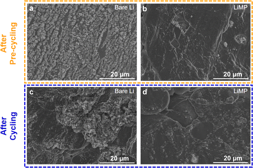 | ||
| Fig. 6 Surface FE-SEM images of (a) bare Li foil and (b) LiMP electrode after pre-cycling, and (c) bare Li foil and (d) LiMP electrode after cycling. | ||
The initial processes of Li plating and stripping significantly impact the reversibility of subsequent cycles and the overall cycle life of the cell. In Fig. 7, the cycling performances of bare Li and LiMP are compared using a symmetric cell configuration. The charge and discharge processes are carried out for 30 minutes, both at current densities of 0.1mA cm−2 (Fig. 7a) and 0.2 mA cm−2 (Fig. 7b). At a current density of 0.1mA cm−2, the LiMP symmetric cell with a CSE exhibits a stable voltage profile for 180 h. In contrast, the bare Li foil exhibits sharp polarization at approximately 160 h during cycling, showing relatively poor cycling performance. To further clarify the dendrite resistance and chemical stability against the Li metal, galvanostatic cycling was performed at a high current density of 0.2 mA cm−2. The bare Li foil shows abrupt overpotential after only 18 h, while the LiMP cell maintains stable cycling for up to 92 h. Fig. 7a and b show similar trends, but the differences are significant, especially at high current densities. The superior cycling performance of LiMP appears to be reasonable, as we confirm through XPS that the Li cell is covered with highly resistive Li2CO3, which has low Li ion diffusion and low electronic conductivity.
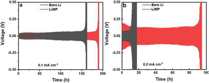 | ||
| Fig. 7 Galvanostatic cycling results at current densities of (a) 0.1 mA cm−2 and (b) 0.2 mA cm−2 in the Li/CSE/Li cell configuration. | ||
The impedance spectra of the bare Li foil before and after cycling are presented in Fig. 8a. The Nyquist plot shows a significant increase after cycling due to the side reaction, which hinders the Li+ transport. The corresponding DRT (distribution of relaxation time) results are depicted in Fig. 8b. Although the Nyquist plot is a valuable tool for impedance analysis, it has certain limitations that can hinder its effectiveness. First, it does not provide precise information on the number of poles and frequency. Second, if the response frequency domain of the polarization peaks differs by a factor of 100, it becomes difficult to distinguish between overlapping physical processes, which can make specific impedance analysis challenging.34 For that reason, we utilized DRT analysis to obtain the specific resistance component. In the Li electrode/CSE/Li electrode system, there are mainly three polarization peaks: (i) bulk resistance of the CSE (denoted as P1), (ii) interfacial resistance between the electrolyte and electrode (denoted as P2), and (iii) resistance related to Li+ diffusion (denoted as P3). Consequently, DRT analysis can separate the overlapped physical processes. Eqn (1) presents the ZDRT calculation formula expressed by converting the impedance spectrum using time constant distribution and frequency information:34
 | (1) |
 | (2) |
 | (3) |
 | (4) |
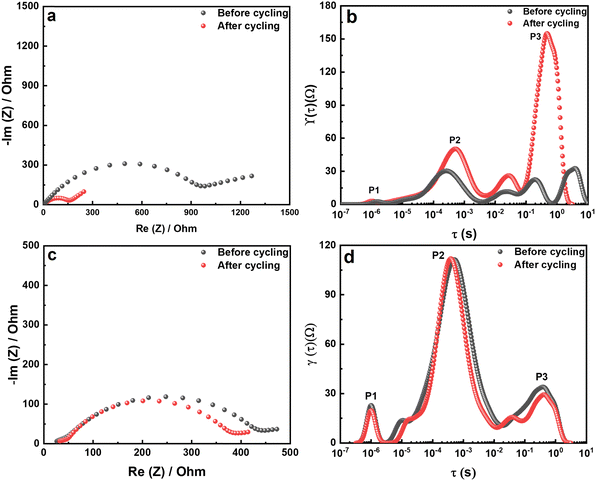 | ||
| Fig. 8 (a) Nyquist plots and (b) the corresponding DRT results for the bare Li foil. (c) Nyquist plots and (d) the corresponding DRT results for the LiMP electrode. | ||
According to the DRT results in Fig. 8b, P3, associated with Li+ diffusion in the electrode, is significantly increased after cycling. Hence, the dominant resistance increase in a symmetrical cell is the result of side reactions in the electrode region. Importantly, P2 in the middle-frequency region shows an increased polarization peak, which demonstrates a thickening of the artificial SEI layer due to the decomposition of the Li salt in the CSE. More importantly, P3 in the high-frequency region shows no difference in the polarization peak. Therefore, the degradation is only caused by the bare Li metal electrode and not by the CSE or other factors. The Nyquist plot of the LiMP electrode is shown in Fig. 8c. The impedance spectra show negligible differences before and after cycling. Thus, we can prove the superior electrochemical stability of the LiMP electrode.
To verify the practical application of LiMP as an anode material, we conducted a full cell test using a LiNi0.6Co0.2Mn0.2 (denoted as NCM622) cathode electrode. Fig. 9a and c show the charge–discharge profiles of LiMP‖CSE‖NCM622 and bare Li‖CSE‖NCM622 cells for 50 cycles. During the initial cycle, a higher polarization behavior is observed in the Li‖CSE‖NCM622 cell due to its surface impurities, which hinder the formation process and consume a larger amount of Li salt for SEI layer formation. In contrast, the LiMP‖CSE‖NCM622 cell exhibits reduced polarization, attributed to LiF compounds. Additionally, the spherical shape of the Li metal powder shows a high surface area, resulting in a homogeneous electric current distribution.36 Consequently, the LiMP anode facilitates the formation of a high-quality SEI layer with lower polarization. During the SEI formation process, while Li‖CSE‖NCM622 displays a severe irreversible Li loss of 79.0%, LiMP‖CSE‖NCM622 exhibits a higher value of 91.3%. This phenomenon proves the aforementioned advantages of Li metal powder as an anode. Fig. 9b and d present the dQ/dV results corresponding to the charge–discharge profiles. Although both samples accurately represent the phase transition behavior of the NCM cathode, the Li‖CSE‖NCM622 cell shows a progressive increase in the voltage range of the redox peak as the cycle progresses.
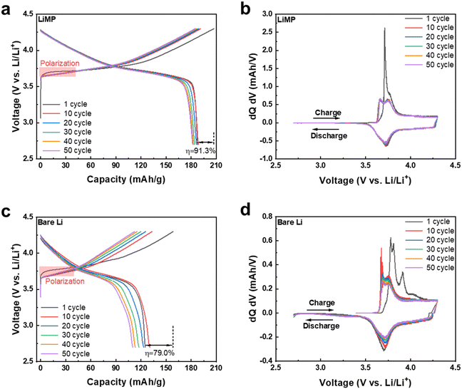 | ||
| Fig. 9 (a) Charge–discharge profiles of LiMP‖CSE‖NCM622 with corresponding (b) dQ/dV results. (c) Charge–discharge profiles of bare Li‖CSE‖NCM622 cells with the corresponding (d) dQ/dV results. | ||
4. Conclusion
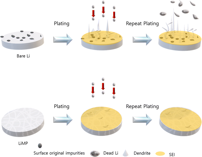
In this study, we proposed a method of applying LiMP as an anode. The LiMP electrode shows various advantages in terms of handling, performance, and safety compared to bare Li foil. Unlike the conventional bare Li foil, the LiMP electrode does not have a basic oxide layer, which prevents uneven Li nucleus generation in the initial stages. This had a positive effect on cycle reversibility and ultimately extended the lifespan of the battery cell. Additionally, by fabricating a solid-state cell, we confirm that the cell configuration of LiMP/CSE/LiMP utilizes the advantage of the uniform Li plating inherent in LiMP. This effectively inhibits the growth of Li dendrites and dead Li, resulting in a significant improvement in the cycle durability. We believe that this research is the only solution for commercializing Li metal anodes, and we will continue to pursue this in future research. To further elucidate the formation of Li dendrites, the comparison of the bare Li foil and LiMP is illustrated in Fig. 10. The bare Li foil with impurities such as Li2CO3 and Li2O induces a local current resulting in inhomogeneous electric field, thus leading to irreversible Li loss during stripping/plating. On the other hand, LiMP does not show dendritic Li growth and dead Li due to the absence of impurities.Author contributions
Seung-Hwan Lee devised the project and supervised this work. Hyeong-Seok Oh performed electromechanical analysis and validation. Rae-Hyun Lee took the lead in writing the manuscript. Jung-Rag Yoon, Hyun-Kyung Kim, and Jong-Kyu Lee contributed to interpreting the results, provided critical feedback, and helped shape the research, analysis, and manuscript. All authors discussed the results and contributed to the final manuscript.Data availability
The datasets used and/or analysed during the current study are available from the corresponding author upon reasonable request.Conflicts of interest
The authors declare that there are no competing interests.Acknowledgements
This work was supported by the Technology Innovation Program (RS-2023-00256202, Development of MLCB Design and Manufacturing Process Technology for Board Mounting) funded by the Ministry of Trade, Industry & Energy (MOTIE, Korea). This work was supported by the Technology Innovation Program (or Industrial Strategic Technology Development Program-Public-private joint investment semiconductor R&D program (K-CHIPS) to foster high-quality human resources) (RS-2023-00237003, high selectivity etching technology using cryoetch) funded by the Ministry of Trade, Industry & Energy (MOTIE, Korea). This work was supported by the National Research Foundation of Korea (NRF) grant funded by the Korean government (MSIT) (RS-2023-00280367).References
- S. Manoharan, K. Krishnamoorthy, A. Sathyaseelan and S.-J. Kim, Mater. Chem. Front., 2021, 5, 6200–6211 RSC.
- X. Huang, S. Cui, J. Chang, P. B. Hallac, C. R. Fell, Y. Luo, B. Metz, J. Jiang, P. T. Hurley and J. Chen, Angew. Chem., Int. Ed., 2015, 54, 1490–1493 CrossRef CAS PubMed.
- J. Xiao, D. Mei, X. Li, W. Xu, D. Wang, G. L. Graff, W. D. Bennett, Z. Nie, L. V. Saraf and I. A. Aksay, Nano Lett., 2011, 11, 5071–5078 CrossRef CAS PubMed.
- S. Liu, X. Wang, D. Xie, X. Xia, C. Gu, J. Wu and J. Tu, J. Alloys Compd., 2018, 730, 135–149 CrossRef CAS.
- K. Mukhopadhyaya and P. Srividya, Trans. Electr. Electron. Mater., 2024, 25, 255–264 CrossRef.
- H. Zhang, L. Wang, H. Li and X. He, ACS Energy Lett., 2021, 6, 3719–3724 CrossRef CAS.
- Y. Ma, J. Wan, Y. Yang, Y. Ye, X. Xiao, D. T. Boyle, W. Burke, Z. Huang, H. Chen and Y. Cui, Adv. Energy Mater., 2022, 12, 2103720 CrossRef CAS.
- Y. Zhang, T.-T. Zuo, J. Popovic, K. Lim, Y.-X. Yin, J. Maier and Y.-G. Guo, Mater. Today, 2020, 33, 56–74 CrossRef CAS.
- S. Shiraishi, K. Kanamura and Z.-I. Takehara, J. Phys. Chem. B, 2001, 105, 123–134 CrossRef CAS.
- K. Kanamura, H. Takezawa, S. Shiraishi and Z. I. Takehara, J. Electrochem. Soc., 1997, 144, 1900 CrossRef CAS.
- K. Xu, Chem. Rev., 2004, 104, 4303–4418 CrossRef CAS PubMed.
- D. Aurbach, E. Zinigrad, Y. Cohen and H. Teller, Solid State Ion., 2002, 148, 405–416 CrossRef CAS.
- G. Derrien, J. Hassoun, S. Panero and B. Scrosati, Adv. Mater., 2007, 19, 2336–2340 CrossRef CAS.
- D. Jin, J. Oh, A. Friesen, K. Kim, T. Jo, Y. M. Lee and M.-H. Ryou, ACS Appl. Mater. Interfaces, 2018, 10, 16521–16530 CrossRef CAS PubMed.
- Z. Han, C. Zhang, Q. Lin, Y. Zhang, Y. Deng, J. Han, D. Wu, F. Kang, Q. H. Yang and W. Lv, Small Methods, 2021, 5, 2001035 CrossRef CAS PubMed.
- Y. Cheng, J. Chen, Y. Chen, X. Ke, J. Li, Y. Yang and Z. Shi, Energy Storage Mater., 2021, 38, 276–298 CrossRef.
- Z. Zhang, Y. Shao, B. Lotsch, Y. Hu, H. Li, J. Janek, L. Nazar, C. Nan, J. Maier and M. Armand, Nat. Rev. Mater., 2017, 2, 16103 CrossRef.
- Z. Xue, D. He and X. Xie, J. Mater. Chem. A, 2015, 3, 19218–19253 RSC.
- P. Verma, P. Maire and P. Novák, Electrochim. Acta, 2010, 55, 6332–6341 CrossRef CAS.
- C.-Z. Zhao, H. Duan, J.-Q. Huang, J. Zhang, Q. Zhang, Y.-G. Guo and L.-J. Wan, Sci. China: Chem., 2019, 62, 1286–1299 CrossRef CAS.
- N. Wu, P. H. Chien, Y. Qian, Y. Li, H. Xu, N. S. Grundish, B. Xu, H. Jin, Y. Y. Hu and G. Yu, Angew. Chem., Int. Ed., 2020, 59, 4131–4137 CrossRef CAS PubMed.
- S. Song, Y. Wu, W. Tang, F. Deng, J. Yao, Z. Liu, R. Hu Alamusi, Z. Wen and L. Lu, ACS Sustainable Chem. Eng., 2019, 7, 7163–7170 CrossRef CAS.
- T. Yang, C. Wang, W. Zhang, Y. Xia, H. Huang, Y. Gan, X. He, X. Xia, X. Tao and J. Zhang, J. Energy Chem., 2023, 84, 189–209 CrossRef CAS.
- M. Baek, J. Kim, K. Jeong, S. Yang, H. Kim, J. Lee, M. Kim, K. J. Kim and J. W. Choi, Nat. Commun., 2023, 14, 1296 CrossRef CAS PubMed.
- B. Xiang, L. Wang, G. Liu and A. M. Minor, J. Electrochem. Soc., 2013, 160, A415 CrossRef CAS.
- S. Ostwald, F. Thoss, M. Zier, M. Hoffmann, T. Jaumann, M. Herklotz, K. Nikolowski, F. Scheiba, M. Kohl and L. Giebeler, Batteries, 2018, 4, 36 CrossRef.
- S.-K. Otto, Y. Moryson, T. Krauskopf, K. Peppler, J. Sann, J. R. Janek and A. Henss, Chem. Mater., 2021, 33, 859–867 CrossRef CAS.
- D. Jin, C. Park, J. Han, C. B. Dzakpasu, E. Kim, J. Oh and Y. M. Lee, Battery Energy, 2023, 2, 20220034 CrossRef CAS.
- J. Ko and Y. S. Yoon, Ceram. Int., 2019, 45, 30–49 CrossRef CAS.
- J. Lang, Y. Long, J. Qu, X. Luo, H. Wei, K. Huang, H. Zhang, L. Qi, Q. Zhang and Z. Li, Energy Storage Mater., 2019, 16, 85–90 CrossRef.
- B. Han, Z. Zhang, Y. Zou, K. Xu, G. Xu, H. Wang, H. Meng, Y. Deng, J. Li and M. Gu, Adv. Mater., 2021, 33, 2100404 CrossRef CAS PubMed.
- Q. Wang, C. Yang, J. Yang, K. Wu, C. Hu, J. Lu, W. Liu, X. Sun, J. Qiu and H. Zhou, Adv. Mater., 2019, 31, 1903248 CrossRef CAS PubMed.
- R. Miao, J. Yang, X. Feng, H. Jia, J. Wang and Y. Nuli, J. Power Sources, 2014, 271, 291–297 CrossRef CAS.
- J. Xia, C. Wang, X. Wang, L. Bi and Y. Zhang, Electrochim. Acta, 2020, 349, 136328 CrossRef CAS.
- X. Ma, Y. Xu, B. Zhang, X. Xue, C. Wang, S. He, J. Lin and L. Yang, J. Power Sources, 2020, 453, 227881 CrossRef CAS.
- J. Heine, S. Krüger, C. Hartnig, U. Wietelmann, M. Winter and P. Bieker, Adv. Energy Mater., 2014, 4, 1300815 CrossRef.
Footnote |
| † Hyung-Seok Oh and Rae-Hyun Lee contributed equally to this work. |
| This journal is © The Royal Society of Chemistry 2024 |


