 Open Access Article
Rutile-type metal dioxide (110) surfaces for the cyclic oxidation of methane to methanol†
Farrel Dzaudan
Naufal
 a,
Hasna
Afifah
b,
Marleni
Wirmas
b,
Mohammad Kemal
Agusta
ac,
Adhitya Gandaryus
Saputro
 ac,
Hadi Teguh
Yudistira
 d,
Aleksandar
Staykov
 e,
Kazunari
Yoshizawa
 f and
Muhammad Haris
Mahyuddin
 *ac
*ac
aQuantum and Nano Technology Research Group, Faculty of Industrial Technology, Institut Teknologi Bandung, Jl. Ganesha 10 Bandung 40132, Indonesia. E-mail: mahyuddin133@itb.ac.id
bDoctoral Program of Engineering Physics, Faculty of Industrial Technology, Institut Teknologi Bandung, Jl. Ganesha 10 Bandung 40132, Indonesia
cResearch Center for Nanoscience and Nanotechnology, Institut Teknologi Bandung, Jl. Ganesha 10 Bandung 40132, Indonesia
dMechanical Engineering Study Program, Institut Teknologi Sumatera, Way Hui, South Lampung 35365, Indonesia
eInternational Institute for Carbon-Neutral Energy Research, Kyushu University, Fukuoka 819-0395, Japan
fFukui Institute for Fundamental Chemistry, Kyoto University, Sakyo-ku, Kyoto 606-8103, Japan
First published on 15th October 2024
Abstract
The direct conversion of methane to methanol has attracted increasing interests, owing to the necessity for an abundant low-carbon source of energy. However, numerous challenges are encountered in attaining a high conversion rate and selectivity using the existing approach and catalysts. One of them is the need for a reaction halt and a reactivation of the catalyst using an oxidant at high temperature, which makes the whole process non-cyclic. In this study, we employ density functional theory calculations to evaluate rutile-type IrO2(110), β-PtO2(110), and β-MnO2(110) surfaces not only for cleaving the H–CH3 bond but also for forming methanol. We find that IrO2(110) and β-PtO2(110) thermodynamically and kinetically favor the C–H activation on the bridging μO-atom terminations via a heterolytic pathway. However, the formation of strong Ir–C and Pt–C bonds, which initially help the C–H bond scission, hinders the methanol formation. In the β-MnO2(110) case, in contrast, the Mn–C interaction is quite weak, and the Mn(μ-O)Mn active site is electrophilic, thus allowing the formation of a stable ˙CH3 radical intermediate state that becomes the driving force for a low-barrier homolytic C–H bond scission as well as a low-barrier and highly exothermic formation of methanol. This first cycle of methane oxidation results in a reduced β-MnO2(110) surface, where no more μ-O active sites are available for the subsequent cycles of methane activation. Nonetheless, this reduced surface can also oxidize methane to methanol when the H2O2 oxidant is inserted in the mid-way reaction and forms new active sites of μ-OH. The second reaction is also highly exothermic although the C–H activation barrier is not as low as that for the fresh stoichiometric surface. This study suggests the β-MnO2(110) surface as a potential catalyst for the cyclic oxidation of methane to methanol using the H2O2 oxidant without halting for reactivation.
1 Introduction
The utilization of earth-abundant low-carbon methane as a transition to renewable energy sources is highly desirable. However, methane, which is mainly present in natural gas, is difficult to store and transport. Therefore, developing an effective yet efficient means to convert methane to liquids such as methanol is considered essential. Unfortunately, the existing method to convert methane to methanol in industries involves a high-temperature formation of syngas (CO and H2 mixture).1,2 This approach, however, is not only costly but also inefficient as the resultant CO needs sequential quasi-catalytic treatments to produce methanol.3,4 In the past decade, the development of heterogeneous catalysts (e.g., metal-exchanged zeolites) for the methane oxidation to methanol had significantly progressed.5–8 In particular, Fe- and Cu-exchanged zeolites have enabled the reaction to proceed at room temperature,9–12 which is crucial to reduce costs and more importantly to avoid an overoxidation to products more stable than methanol.13–15 Accordingly, this has inspired broad development of new catalysts such as single-metal-modified surfaces such as graphene, CeO2, TiO2, ZnO, CuO, etc.16–23In these mono/diatomic-dispersed catalysts, however, the methane conversion undergoes the so-called stepwise reaction, where the catalyst must first be activated with O2 or N2O at high temperature to form the active metal–oxo sites prior to the main reaction of methane oxidation to methanol that takes place at a lower temperature.24–27 After the first cycle of the reaction, the reaction must then be halted and the reduced catalyst must be reactivated using the same oxidant to continue the reaction to the second cycle and so on. This, consequently, makes the catalysts unpractical for industrial purposes. Attempts to make it more catalytic (i.e., cyclic/continuous reaction) have also been reported, but this approach is less preferred than the stepwise one due to the need for a higher temperature to decompose the oxidant, which accordingly increases the probability for overoxidation to occur and thus gives rise to selectivity issues.28–31
In 2017, Liang et al.32 reported that the rutile-type IrO2(110) surface is highly active for H–CH3 bond scission at temperatures as low as 150 K with an extremely low activation barrier of 0.1 eV. Tsuji and Yoshizawa,33 by means of density functional theory (DFT) calculations, then elucidated that the IrO2(110) distorts the geometry of methane (C–H bond elongation and H–C–H angle widening) at the early stage of activation and cleaves the C–H bond in a heterolytic fashion that leads to the formation of a strong Ir–CH3 bond, which explains the high activity of the catalyst. They also suggested β-PtO2(110) as a catalyst that is more active than IrO2(110) for the H–CH3 bond scission owing to more geometrical distortions of the adsorbed methane and a stronger Pt–CH3 bond.33 Despite this, however, an excessively strong metal–CH3 bond would lead to a new challenge when considering the energy required for the metal–CH3 bond cleavage and the following HO–CH3 recombination to form methanol. This is evident from the works by Yeh et al.34 and Martin et al.,35 showing that formaldehyde and CHyO2, instead of methanol, are two favorable products for methane oxidation on IrO2(110) in the presence and absence of O2, respectively. Also, Tsuji et al.36 and Takagaki et al.37 have shown that, only through engineering schemes such as nitrogen doping, oxygen defects, and applying supports, β-PtO2(110) can convert methane to methanol.
In this study, we use DFT calculations to evaluate three rutile-type metal oxide surfaces, including IrO2(110), β-PtO2(110), and β-MnO2(110), not only for catalyzing the methane activation but also for the methanol formation. Being the focus of this study, β-MnO2(110) is found to easily cleave the H–CH3 bond through a homolytic pathway, where a free ˙CH3 radical, instead of a Mn–CH3 ligand, is formed as the reaction intermediate, which contrasts the heterolytic mechanism favored by IrO2(110) and β-PtO2(110), and becomes the reason for an easy formation of methanol. This paper also discusses the origin of such different mechanisms and the possibility for the reduced β-MnO2(110) to proceed the second cycle of the reaction by introducing H2O2 in the mid-way, which renders the catalyst potential for the cyclic (continuous) oxidation of methane to methanol without halting for reactivation.
2 Computational details
IrO2, β-PtO2, and β-MnO2 are rutile-type crystals, where the latter two, in particular, have a distorted crystal structure. The optimized bulks were found to have lattice parameters of a = b = 4.522 Å and c = 3.184 Å for IrO2; a = 3.089 Å, b = 4.519 Å, and c = 4.455 Å for β-PtO2; and a = b = 4.474 Å and c = 2.972 Å for β-MnO2. These optimized bulks were then used to construct 5 × 2 slab models with nine atomic layers of surface and 15 Å of vacuum for each, a large enough separation to minimize the effect of interactions between the periodically repeated adsorbates. The three topmost atomic layers were allowed to relax in all directions, while the rest were constrained to their optimized positions to represent the bulk.Spin-polarized calculations were performed using the Kohn–Sham formulation38,39 as implemented in the Vienna Ab initio Simulation Package (VASP) version 5.4.4.40,41 The projector augmented wave (PAW) method was employed to describe the interaction between cores and electrons.42,43 The electron exchange–correlation was treated using the Perdew–Burke–Ernzerhof (PBE)44 functional based on the generalized gradient approximation (GGA). The plane-wave basis set with a sufficient cut-off energy of 500 eV (Fig. S1, ESI†) was used for all calculations. Considering the large slab models used here, we restricted the Brillouin zone sampling to the Γ point only except for PDOS calculations, in which a 3 × 3 × 1 k-point mesh was used. The zero-damping D3 method was utilized to account for the dispersion correction.45 The GGA+U method of Dudarev's simplified rotationally invariant approach46 was used with Ueff values of 7.5 and 5.1 eV, respectively, for the Pt 5d and Mn 3d orbitals, as optimized previously.33,47,48 The use of different Ueff values was tested to insignificantly alter the relative energies (Fig. S2, ESI†). Unlike these two metal orbitals, the Ir 5d orbital exhibits a weak on-site Coulomb interaction of electrons, making the GGA+U treatment unnecessary, consistent with previous studies.32,33 Due to a great number of metal atoms involved in the present slab surface models, as opposed to the mono/diatomic systems, the spin configuration was not set to a specific spin state. Instead, we let VASP optimize the spin state along with the geometry optimization. Therefore, when the calculations converged, both the geometry and the spin configuration were in the ground state. This is a standard well-accepted method used for many surface systems.16,33,47–49
The conjugate gradient method was employed to optimize intermediate structures, while the climbing-image nudged elastic band (CI-NEB) method was used to locate transition states (TSs).50 The image-dependent pair potential method was used to generate initial images for the CI-NEB calculations.51 The calculations were considered converged when the maximum forces on the unconstrained atoms are below 0.03 eV Å−1. To confirm the presence of a saddle point, vibration frequency calculations were performed using the finite difference method with a small displacement of 0.015 Å. The Bader analysis algorithm52 was used to calculate atomic spin density, and optimized structures were visualized by using VESTA.53 The bonding orbital analysis was performed using the projected crystal orbital Hamilton population (pCOHP) method, as implemented in the LOBSTER package.54–58
The surface formation energy (Esurf) was calculated by using the following formula under the assumption that the surface was formed by cleaving the bulk structure.
| Eads = Eslab+A − (Eslab + EA) |
| EB(M−C) = Eslab+CH3 − (Eslab + ECH3) |
where Eslab+H and EH2 are the total energies of a single H atom adsorbed on the surface O atom and an isolated H2 molecule, respectively.
3 Results and discussion
3.1 Stability of the (110) surfaces
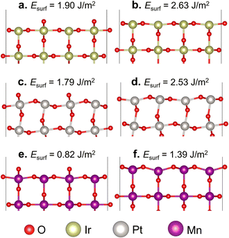
In the formation of the (110) surface from rutile-type metal oxides, there are two possible terminations on the topmost layer, namely the O- and M-terminated (110) surfaces (Fig. 1). In these two slab surface models, we have ensured that they consist of symmetrically arranged layers of positive and negative charges, thus exhibiting no net dipole moment perpendicular to the surface normal, which is aligned with the Tasker rules.60 The calculated Esurf shows that the O-terminated surface model for all three studied oxides is easier to form than the M-terminated one. This suggests that the cleavage of IrO2, β-PtO2, and β-MnO2 in a direction perpendicular to [110] tends to form layers covered with two-coordinated bridging O (μ-O) atoms, which is consistent with previous studies.32,48,61 On the other hand, the M-terminated (110) surface involves one-coordinated dangling O atoms, which makes it less stable. Thus, in the next section, we consider only the O-terminated (110) surface (hereafter referred to as the stoichiometric surface) for evaluating the oxidation of methane to methanol.3.2 Methane oxidation on the stoichiometric surface
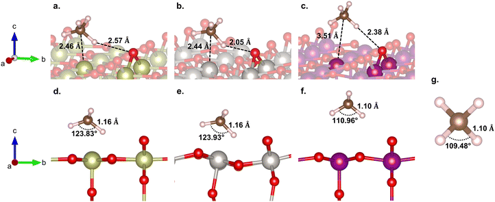
Here, we consider the bridging μO-atom terminations as the active sites abstracting the H atom of methane and being consumed to form methanol. Another reaction possibility of H2O2 being introduced together with methane to the surface was also considered. However, in this scenario, H2O2 decomposes into OOH + μOH (Fig. S3, ESI†), and the following methane reaction with the formed μOH proceeds according to the discussion in section 3.4. Therefore, we first focus our discussion of this section only on the former scenario.Fig. 2 shows the reaction energy diagrams for all three studied surfaces, while the optimized structures for each reaction step are shown in Fig. S4 (ESI†). The reaction involves three elementary steps, namely methane adsorption, C–H bond activation, and methanol formation. In the first step, as expected, IrO2(110) and β-PtO2(110) strongly adsorb methane with adsorption energies (Eads) of −0.75 and −0.65 eV, respectively, whereas β-MnO2(110) weakly adsorbs methane (Eads = −0.22 eV). Looking at the geometry of the adsorbed methane (Fig. 3), we find that only IrO2(110) and β-PtO2(110) are quite close to the adsorbed methane, which is a clear indication of a strong chemical adsorption. This chemisorption forms C–Ir and C–Pt interactions that distort the geometry of methane. As shown in Fig. 3d and e, a significant widening of the ∠H–C–H angle to about 124° and a C–H bond elongation to 1.16 Å are observed, consistent with the previous work of Tsuji and Yoshizawa.33 In the β-MnO2(110) case (Fig. 3c and f), on the other hand, the weakly adsorbed methane is quite far from the surface and no geometrical distortions are observed (see Fig. 3g for methane geometry in the gas phase), which indicate a physisorption.
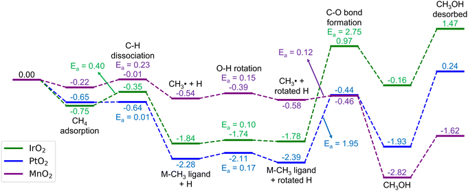 | ||
| Fig. 2 Energy diagrams (in eV) for the methane oxidation to methanol on the stoichiometric IrO2(110), β-PtO2(110), and β-MnO2(110) surfaces. The corresponding optimized geometries are shown in Fig. S4 (ESI†). | ||
In the subsequent C–H activation step, two well-studied pathways (i.e., the homolytic and heterolytic bond scissions that lead to the formation of a ˙CH3 radical and an M–CH3 ligand intermediate states, respectively) were considered, as many reports also focused on these.62,63 However, the IrO2(110) and β-PtO2(110) surfaces disfavor the homolytic pathway as the calculations for the formation of the ˙CH3 radical cannot converge to the minimum required accuracy and eventually forms Ir–CH3 and Pt–CH3 ligands. In contrast, as shown in Fig. 2, the formation of both the ˙CH3 radical and Mn–CH3 ligand on β-MnO2(110) is favored, enabling us to calculate both the homolytic and heterolytic C–H bond scissions. However, interestingly, after the NEB calculations, we find that the TS structures found for both pathways are similar, which are radical-like TSs. Moreover, the Mn–CH3 ligand formation (ΔE = −0.51 eV) is found to be slightly less stable than the ˙CH3 radical formation (ΔE = −0.54 eV). These clearly indicate that the C–H activation on β-MnO2(110) indeed favors the homolytic pathway.
In terms of energetics, among the studied catalysts, the C–H activation barrier is calculated as the lowest for β-PtO2(110) (Ea = 0.01 eV), the middle for β-MnO2(110) (Ea = 0.23 eV), and the highest for IrO2(110) (Ea = 0.40 eV). It is worth noting that the TSs for β-PtO2(110) and IrO2(110) are more stable than the reference (i.e., methane in the gas phase), suggesting that the actual (apparent) activation barrier for IrO2(110) and β-PtO2(110) might be lower, as also reported by Liang et al.32 In terms of geometry (Fig. 4), the heterolytic C–H bond scission on IrO2(110) and β-PtO2(110) results in a four-centered TS, where the resultant CH3− fragment separates from the H+ fragment while interacting with the surface metal atom (M⋯C distance < 2.31 Å). In contrast, the bond scission on β-MnO2(110) results in a ˙CH3-like species (i.e., the geometry has not been fully planar yet, but somewhere in between tetrahedral and planar structures) that separates from both the Mn and H atoms and forms an almost planar geometry.
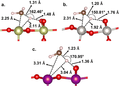 | ||
| Fig. 4 Geometries of the C–H transition state on (a) IrO2(110), (b) β-PtO2(110), and (c) β-MnO2(110) surfaces. | ||
In Fig. 5, the geometries of the M–CH3 ligand and ˙CH3 radical intermediate states are shown. The Ir–, Pt–, and Mn–CH3 bond lengths are measured to be 2.07, 2.00, and 2.26 Å, respectively, which are consistent with their corresponding bond formation energies (EB(M–C) = −2.90, −2.53, and −0.59 eV, respectively). This suggests that the Mn–C bond is so weak that it is not more stable than the ˙CH3 formation that has a longer Mn⋯C distance (2.65 Å). Thus, we infer that the methane conversion to methanol on β-MnO2(110) most probably proceeds through an intermediate state of the ˙CH3 radical without being preceded or succeeded by the Mn–CH3 formation. The formation of the ˙CH3 radical is indicated by a planar sp2 geometry of CH3 (Fig. 5d) and the presence of a single unpaired electron on the C atom.
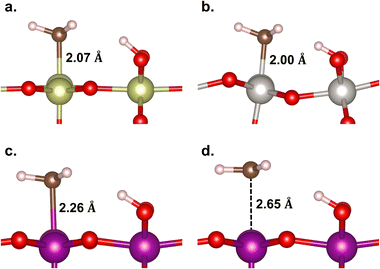 | ||
| Fig. 5 Geometries of the M–CH3 ligand on (a) IrO2(110), (b) β-PtO2(110), and (c) β-MnO2(110) surfaces, and (d) the ˙CH3 radical on β-MnO2(110). | ||
The next elementary step is the methanol formation. Here, the CH3 moiety or ˙CH3 radical recombines with the OH moiety that resulted from the prior methane activation. Other possible pathways such as solvent-assisted methanol formation15 might also be possible but were excluded from the consideration for the sake of conciseness. To facilitate the HO–CH3 recombination pathway, the OH fragment needs to rotate in a way that the H atom of the OH fragment points outward from the CH3, while the O end of the OH fragment faces toward the CH3, as also considered in our previous studies.12,20,64 As shown in Fig. 2, this process is found to be low-barrier for all the studied catalysts (Ea = 0.1, 0.17, and 0.15 eV, respectively, for IrO2(110), β-PtO2(110), and β-MnO2(110)).
The recombination between the CH3− and the rotated OH on the IrO2(110) and β-PtO2(110) surfaces requires a quite high activation barrier (Ea = 2.75 and 1.95 eV, respectively), the latter of which agrees well with the work of Tsuji et al. (2.07 eV).36 Such a high Ea is as expected from the strong Ir–CH3 and Pt–CH3 bonds that need to be cleaved before the recombination. However, not to our expectation, the formation of methanol chemisorbed on these two surfaces is highly endothermic (ΔE = 1.62 and 0.46 eV, respectively, for IrO2(110) and β-PtO2(110)). These highly unfavored thermodynamic and kinetic aspects suggest that the methanol formation on these two oxide surfaces is unlikely to happen and, instead, stops at the formation of Ir–CH3 and Pt–CH3 bonds only.
In the β-MnO2(110) case, in contrast, the methanol formation proceeds through a recombination between the ˙CH3 and OH fragments with a low barrier (Ea = 0.12 eV) and high exothermicity (ΔE = −2.24 eV). Such a highly favored methanol formation may be attributed to the higher stability of Mn3+ (3d4) in the resultant Mn3+–CH3OH–Mn3+ as compared to Mn4+ (3d3) in the CH4 adsorption state. This is also evidenced from the −pCOHP calculations of the methanol formation (Fig. S5, ESI†) showing that the Mn–O antibonding orbital is located at a higher energy than the Ir–O and Pt–O antibonding orbitals, which again indicates that the Mn–O bonds are stronger and thus stabilize the system more significantly. On top of that, β-MnO2(110) also desorbs methanol with a desorption energy (1.20 eV) being the lowest among the three studied catalysts (1.63 and 2.17 eV, respectively, for IrO2(110) and β-PtO2(110)) and comparable to that for the zeolites.64,65 The geometrical parameters of the methanol adsorbed on the three catalysts are shown in Fig. S6 (ESI†). Fig. S7 (ESI†) shows a good Brønsted–Evans–Polanyi (BEP) relation66,67 between Ea and ΔE for HO–CH3 formation, suggesting that a more stable methanol formation requires a lower Ea. We have also tried to relate the Ea of HO–CH3 formation to the O p-band center, as suggested by Ge and co-workers.68,69 However, unfortunately, there seems no high dependency of the HO–CH3 formation on the O p-band center (Fig. S8, ESI†).
We have also evaluated the stability of the formaldehyde (CH2O) and dimethyl ether (C6H2O) formation as two possible side products of methanol overoxidation. As shown in Fig. S9 (ESI†), two alternative pathways (CH4(g) → CH2O* + H2(g) and 2CH4(g) → C2H6O* + H2(g)) are considered, and it is found that the formation of CH2O and C6H2O on all studied surface catalysts is much less stable than the methanol formation. This suggests that the overoxidation of methanol is unlikely to occur.
Overall, the reaction on β-MnO2(110) is exothermic (ΔE = −1.62 eV) with a rate-determining barrier of only 0.23 eV and a highly favorable methanol formation as compared to the CH2O and C6H2O formation. In contrast, the reaction on IrO2(110) and β-PtO2(110) surfaces initially proceeds with a low C–H barrier but then encounters difficulties in the formation and desorption of methanol with high endothermicity and a rate-determining barrier of >1.9 eV, making them unsuitable for catalyzing the direct conversion of methane to methanol.
3.3 Electronic structure analysis
From the discussion above, two questions arise: (1) why does β-MnO2(110) favor the homolytic C–H scission, while IrO2(110) and β-PtO2(110) favor the heterolytic one and (2) why is the ˙CH3 + OH formation on β-MnO2(110) more stable than the methane adsorption? To answer the first question, we calculate the strength of M–C and O–H bonds formed in the M–CH3 + O–H intermediate state to analyze which of the two contributes more to the stabilization of the intermediate state. As shown in Table 1, the Ir–CH3 binding energy is two times higher than the O–H binding energy, suggesting that the Ir–C bond is extremely strong and thus contributes more to the state stabilization. On β-PtO2(110), on the other hand, both the Pt–CH3 and O–H bonds contribute equally to the stabilization, whereas for β-MnO2(110), the O–H bond contributes predominantly to the formation of the Mn–CH3 + O–H ligand state, indicating that the Mn–C bond is indeed weak. This table, thus, infers that the Ir–C and Pt–C interactions are strong enough to prevent the formation of ˙CH3 as an intermediate state, making the homolytic C–H bond scission unfavorable for IrO2(110) and β-PtO2(110) surfaces. Also, this suggests that the C–H activation of methane on β-MnO2(110) is driven more predominantly by the O–H bond formation, as also previously suggested by Liu et al. for methane activation on metal-zeolites.70| Metal oxide surface | E B(M–C) (eV) | E B(O–H) (eV) |
|---|---|---|
| IrO2(110) | −2.90 | −1.35 |
| β-PtO2(110) | −2.53 | −2.23 |
| β-MnO2(110) | −0.59 | −2.49 |
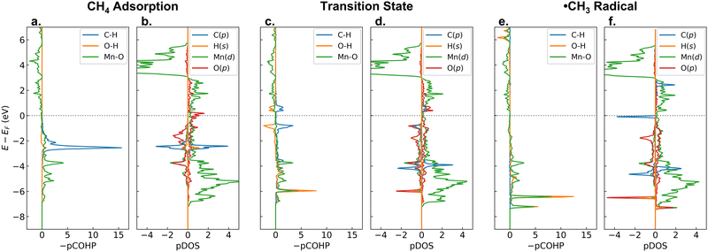
Now, to answer the second question, let us analyze the changes of −pCOHP and PDOS during the C–H activation on β-MnO2(110). Fig. 6 shows the −pCOHP values of the dissociated C–H, the formed O–H, and the bridging Mn–O bonds as well as PDOS of the C-p, abstracted H-s, active Mn-d, and bridging O-p orbitals for the adsorption, transition, and intermediate states of methane activation. In Fig. 6a and b, we can see the degenerate σC–H bonding orbitals of methane as they are in the gas phase (see also Fig. S10 (ESI†), only the energy shifts due to the presence of the surface that alters the Fermi level (EF)), indicating a weak adsorbate–surface interaction where the adsorbed methane is undistorted geometrically and electronically. During the homolytic C–H bond scission, the α-electron of the shared electrons in the C–H bond is taken by the H atom, while the β-electron is taken by the C atom. The α electron carried by the H atom is readily transferred to the antibonding Mn–O orbital, as indicated by the presence of a newly formed MnO–H bonding orbital at a low energy (green and orange lines at about −6 eV in Fig. 6c). The β electron, on the other hand, singly occupies the antibonding C-p orbital and forms a free ˙CH3 radical, as indicated by the presence of an occupied C-p β-orbital and an unoccupied C-p α-orbital in the vicinity of the EF (blue line in Fig. 6d). After the ˙CH3 formation, the MnO–H bonding orbital becomes double due to the involvement of two Mn atoms bridging the OH moiety and shifts downward to slightly lower energies (Fig. 6e), indicating that the O–H bond becomes stronger. The unoccupied antibonding C-p α-orbital, on the other hand, shifts upward away from the EF (Fig. 6f), indicating that the ˙CH3 is stabilized. Such an electrophilic mechanism, where a transfer of the C–H α-electron leads to a stabilization of the radical intermediate state (˙CH3 + O–H) and becomes the driving force for the C–H bond activation, is similar to the [FeO]2+-ZSM-5 case.71 It is worth noting that in the formation of the Mn–CH3 + O–H intermediate state, no electron transfer and redox occur, thus explaining the low stability of the Mn–CH3 and O–H bonds.
3.4 Methane oxidation on reduced β-MnO2(110) using the H2O2 oxidant
Here, we can consider two possibilities of the H2O2 insertion: (1) being introduced together with methane to the stoichiometric surface, where the H2O2 decomposition to H + OOH proceeds earlier than the methane activation (Fig. S3, ESI†); or (2) being inserted in the mid-way reaction after a reduced surface is formed due to the consumption of all the μ-O terminations by the prior oxidation of methane (H2O2 decomposition to 2OH; Fig. S11, ESI†). Whichever the case, the μ-O terminations become μ-OH terminations that now abstract the H atom of methane. Thus, in this section, we focus our discussion on the reduced surface only. As shown in Fig. 7, the H2O2 decomposes favorably on the reduced β-MnO2(110) surface into 2OH rather than H + OOH (Fig. S11, ESI†). This is possibly due to the absence of the bridging μO-atom terminations that may accommodate the dissociated H atom of H2O2. Fig. 7 shows that the H2O2 is first adsorbed on the reduced surface with a rather high Eads of −0.80 eV. The HO–OH bond then dissociates into two OH fragments with a low activation barrier (Ea = 0.04 eV) to form two stable Mn–OH–Mn species with a quite high exothermicity (ΔE = −3.11 eV).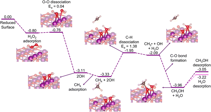 | ||
| Fig. 7 Energy diagram (in eV) for CH4 oxidation to CH3OH on the reduced β-MnO2(110) surface with H2O2 as the oxidation agent. | ||
In the subsequent reaction steps, we consider methane adsorption on the OH-decorated surface, followed by a C–H bond activation via the homolytic pathway to directly form methanol. As shown in Fig. 7, the adsorption of methane is rather weak (Eads = −0.22 eV), as also observed previously for the stoichiometric surface (Fig. 2). One H atom of methane is then abstracted in a homolytic fashion with Ea = 1.38 eV and accepted by one of the OH moieties forming a H2O molecule adsorbed on the surface, while the remaining CH3 fragment forms a free radical species as an intermediate state before the direct formation of methanol takes place. Comparing this to a mechanism where an Mn–CH3 ligand is formed as an intermediate state, instead of ˙CH3, we find a similar Ea and transition structure (Fig. S12, ESI†), indicating that the homolytic pathway is indeed favored. Moreover, the Mn–CH3 formation (ΔE = −2.16 eV) is found to be significantly less stable than the methanol formation (ΔE = −3.96 eV), suggesting that the ˙CH3 radical may directly form methanol without forming Mn–CH3 as another intermediate state, as also indicated previously in Fig. 2. The desorption energy of methanol in this case (Edes = 0.91 eV) is found to be lower than that in the stoichiometric surface case (1.20 eV). Along with methanol, the formed H2O molecule also desorbs facilely with an Edes of only 0.74 eV, which thus forms the reduced β-PtO2(110) surface again. The subsequent cycles of the CH4 + H2O2 → CH3OH + H2O reaction can then again proceed repeatedly.
Although the calculated C–H activation barrier for this reduced surface case is much higher than that for the stoichiometric surface case, the overall reaction is downhill and highly exothermic. Furthermore, using H2O2 as the oxidant allows the reaction to proceed in a cyclic fashion, where CH4 and H2O2 are introduced together or mid-way continuously to the reactor without halting for reactivation treatments. These suggest that β-MnO2(110), in the form of either an O- or an M-terminated surface, has the potential for oxidizing methane to methanol.
We have also considered O2 as a possible oxidant to form the stoichiometric surface back. Unfortunately, as shown in Fig. S13 (ESI†), the activation energy for the O–O dissociation (Ea = 2.30 eV) is quite high, and the overall reaction is slightly endothermic (ΔE = 0.06 eV). This suggests that the reduced surface needs to be exposed to a high O2 pressure at elevated temperature to regain the active surface, which is unfavorable for practical purposes of methane direct conversion to methanol.
4 Conclusions
By means of DFT calculations, we have investigated the possibility and mechanism of methane direct oxidation to methanol on three rutile-type metal oxide surfaces, namely IrO2(110), β-PtO2(110), and β-MnO2(110). The three catalysts, through their bridging O-atom terminations on the topmost layer, are found to be highly active toward the C–H bond activation (Ea < 0.4 eV). However, only β-MnO2(110) can oxidize the resultant CH3 into methanol. Such an ability discrepancy is due to the formation of strong Ir–CH3 and Pt–CH3 bonds during the reaction via heterolytic C–H bond scission, consequently increasing the energy required to break the Ir–CH3 and Pt–CH3 bonds and to recombine with the OH ligand. In contrast, for the β-MnO2(110) case, the formation of a free ˙CH3 radical as the reaction intermediate instead of an Mn–CH3 ligand facilitates a direct recombination of OH and CH3 without the need for any prior bond breaking. The ability of β-MnO2(110) to form a stable ˙CH3 radical that drives the reaction to proceed with a low C–H activation barrier owes to the electrophilic nature of the surface.We have also evaluated the possibility for the reduced β-MnO2(110) surface to again oxidize methane to methanol by introducing the H2O2 oxidant in the mid-way reaction. We find that the H2O2 facilely decomposes to 2OH, which becomes the new active site for the methane activation. The overall reaction is found to be highly exothermic, and the calculated barrier for the rate-determining C–H activation (Ea = 1.38 eV) is moderate, much lower than the barrier calculated for the rate-determining methanol formation on IrO2(110) and β-PtO2(110). This renders β-MnO2(110) potential for catalyzing the CH4 + H2O2 → CH3OH + H2O reaction in a cyclic fashion.
Author contributions
F. D. N.: data curation, investigation, methodology, visualization, writing – original draft; H. A.: writing – review & editing; M. W.: writing – review & editing; M. K. A.: supervision, validation, writing – review & editing; A. G. S.: supervision, writing – review & editing; H. T. Y.: writing – review & editing; A. S.: formal analysis, writing – review & editing; K. Z.: writing – review & editing; M. H. M.: conceptualization, funding acquisition, formal analysis, writing – review & editing.Data availability
The data supporting this article have been included as part of the ESI.†Conflicts of interest
There are no conflicts to declare.Acknowledgements
This work was supported by the Indonesia Endowment Fund for Education (LPDP) and Indonesian Science Fund (DIPI) through the RISPRO International Collaboration research scheme (grant no. RISPRO/KI/B1/KOM/11/15539/1/2020). The computations were partly performed at the Research Institute for Information Technology of Kyushu University.References
- J. H. Lunsford, Catal. Today, 2000, 63, 165–174 CrossRef CAS.
- Z. Zakaria and S. K. Kamarudin, Renewable Sustainable Energy Rev., 2016, 65, 250–261 CrossRef CAS.
- H. D. Gesser, N. R. Hunter and C. B. Prakash, Chem. Rev., 1985, 85, 235–244 CrossRef CAS.
- H. Schulz, Appl. Catal., A, 1999, 186, 3–12 CrossRef CAS.
- M. H. Mahyuddin, Y. Shiota, A. Staykov and K. Yoshizawa, Acc. Chem. Res., 2018, 51, 2382–2390 CrossRef CAS PubMed.
- B. E. R. Snyder, M. L. Bols, R. A. Schoonheydt, B. F. Sels and E. I. Solomon, Chem. Rev., 2018, 118, 2718–2768 CrossRef CAS PubMed.
- N. F. Dummer, D. J. Willock, Q. He, M. J. Howard, R. J. Lewis, G. Qi, S. H. Taylor, J. Xu, D. Bethell, C. J. Kiely and G. J. Hutchings, Chem. Rev., 2022, 123, 6359–6411 CrossRef PubMed.
- M. Ravi, M. Ranocchiari and J. A. van Bokhoven, Angew. Chem., Int. Ed., 2017, 56, 16464–16483 CrossRef CAS PubMed.
- J. S. Woertink, P. J. Smeets, M. H. Groothaert, M. A. Vance, B. F. Sels, R. A. Schoonheydt and E. I. Solomon, Proc. Natl. Acad. Sci. U. S. A., 2009, 106, 18908–18913 CrossRef CAS PubMed.
- P. Vanelderen, B. E. R. Snyder, M.-L. Tsai, R. G. Hadt, J. Vancauwenbergh, O. Coussens, R. A. Schoonheydt, B. F. Sels and E. I. Solomon, J. Am. Chem. Soc., 2015, 137, 6383–6392 CrossRef CAS PubMed.
- M. L. Bols, S. D. Hallaert, B. E. R. Snyder, J. Devos, D. Plessers, H. M. Rhoda, M. Dusselier, R. A. Schoonheydt, K. Pierloot, E. I. Solomon and B. F. Sels, J. Am. Chem. Soc., 2018, 140, 12021–12032 CrossRef CAS PubMed.
- M. H. Mahyuddin, E. T. Lasiman, A. G. Saputro, S. V. Casuarina, N. Nugraha and H. K. Dipojono, Catal. Sci. Technol., 2023, 13, 5767–5775 RSC.
- M. J. Wulfers, R. F. Lobo, B. Ipek and S. Teketel, Chem. Commun., 2015, 51, 4447–4450 RSC.
- M. B. Park, S. H. Ahn, M. Ranocchiari and J. van Bokhoven, ChemCatChem, 2017, 9, 3705–3713 CrossRef CAS.
- M. H. Mahyuddin, S. Tanaka, R. Kitagawa, A. L. Maulana, A. G. Saputro, M. K. Agusta, H. T. Yudistira, H. K. Dipojono and K. Yoshizawa, J. Phys. Chem. C, 2021, 125, 19333–19344 CrossRef CAS.
- R. K. Singha, Y. Tsuji, M. H. Mahyuddin and K. Yoshizawa, J. Phys. Chem. C, 2019, 123, 9788–9798 CrossRef CAS.
- Z. Liu, E. Huang, I. Orozco, W. Liao, R. M. Palomino, N. Rui, T. Duchoň, S. Nemšák, D. C. Grinter, M. Mahapatra, P. Liu, J. A. Rodriguez and S. D. Senanayake, Science, 2020, 368, 513–517 CrossRef CAS PubMed.
- X. Cui, H. Li, Y. Wang, Y. Hu, L. Hua, H. Li, X. Han, Q. Liu, F. Yang, L. He, X. Chen, Q. Li, J. Xiao, D. Deng and X. Bao, Chem, 2018, 4, 1902–1910 CAS.
- Y. Qin, H. Liu, L. Li, J. Han, H. Wang, X. Zhu and Q. Ge, J. Catal., 2023, 417, 323–333 CrossRef CAS.
- R. P. P. Sukanli, M. H. Mahyuddin, A. G. Saputro, M. K. Agusta, H. T. Yudistira, K. Yoshizawa and H. K. Dipojono, ACS Appl. Nano Mater., 2023, 6, 6559–6566 CrossRef CAS.
- Q. Shen, C. Cao, R. Huang, L. Zhu, X. Zhou, Q. Zhang, L. Gu and W. Song, Angew. Chem., Int. Ed., 2020, 59, 1216–1219 CrossRef CAS PubMed.
- E. Huang, I. Orozco, P. J. Ramírez, Z. Liu, F. Zhang, M. Mahapatra, S. Nemšák, S. D. Senanayake, J. A. Rodriguez and P. Liu, J. Am. Chem. Soc., 2021, 143, 19018–19032 CrossRef CAS PubMed.
- S. Bai, Y. Xu, P. Wang, Q. Shao and X. Huang, ACS Catal., 2019, 9, 6938–6944 CrossRef CAS.
- E. M. C. Alayon, M. Nachtegaal, A. Bodi and J. A. van Bokhoven, ACS Catal., 2014, 4, 16–22 CrossRef CAS.
- V. L. Sushkevich, D. Palagin and J. A. van Bokhoven, Angew. Chem., Int. Ed., 2018, 57, 8906–8910 CrossRef CAS PubMed.
- D. K. Pappas, A. Martini, M. Dyballa, K. Kvande, S. Teketel, K. A. Lomachenko, R. Baran, P. Glatzel, B. Arstad, G. Berlier, C. Lamberti, S. Bordiga, U. Olsbye, S. Svelle, P. Beato and E. Borfecchia, J. Am. Chem. Soc., 2018, 140, 15270–15278 CrossRef CAS PubMed.
- S. Grundner, M. A. C. Markovits, G. Li, M. Tromp, E. A. Pidko, E. J. M. Hensen, A. Jentys, M. Sanchez-Sanchez and J. A. Lercher, Nat. Commun., 2015, 6, 7546 CrossRef PubMed.
- K. Narsimhan, K. Iyoki, K. Dinh and Y. Román-Leshkov, ACS Cent. Sci., 2016, 2, 424–429 CrossRef CAS PubMed.
- J. Xu, R. D. Armstrong, G. Shaw, N. F. Dummer, S. J. Freakley, S. H. Taylor and G. J. Hutchings, Catal. Today, 2016, 270, 93–100 CrossRef CAS.
- K. T. Dinh, M. M. Sullivan, K. Narsimhan, P. Serna, R. J. Meyer, M. Dincă and Y. Román-Leshkov, J. Am. Chem. Soc., 2019, 141, 11641–11650 CrossRef CAS PubMed.
- Y. K. Chow, N. F. Dummer, J. H. Carter, C. Williams, G. Shaw, D. J. Willock, S. H. Taylor, S. Yacob, R. J. Meyer, M. M. Bhasin and G. J. Hutchings, Catal. Sci. Technol., 2018, 8, 154–163 RSC.
- Z. Liang, T. Li, M. Kim, A. Asthagiri and J. F. Weaver, Science, 2017, 356, 299–303 CrossRef CAS PubMed.
- Y. Tsuji and K. Yoshizawa, J. Phys. Chem. C, 2018, 122, 15359–15381 CrossRef CAS.
- C. H. Yeh, T. M. Le Pham, S. Nachimuthu and J. C. Jiang, ACS Catal., 2019, 9, 8230–8242 CrossRef CAS.
- R. Martin, C. J. Lee, V. Mehar, M. Kim, A. Asthagiri and J. F. Weaver, ACS Catal., 2022, 12, 2840–2853 CrossRef CAS.
- Y. Tsuji, K. Kurino and K. Yoshizawa, ACS Omega, 2021, 6, 13858–13869 CrossRef CAS PubMed.
- A. Takagaki, Y. Tsuji, T. Yamasaki, S. Kim, T. Shishido, T. Ishihara and K. Yoshizawa, Chem. Commun., 2023, 59, 286–289 RSC.
- P. Hohenberg and W. Kohn, Phys. Rev., 1964, 136, B864–B871 CrossRef.
- W. Kohn and L. J. Sham, Phys. Rev., 1965, 140, A1133–A1138 CrossRef.
- G. Kresse and J. Furthmüller, Comput. Mater. Sci., 1996, 6, 15–50 CrossRef CAS.
- G. Kresse and J. Furthmüller, Phys. Rev. B: Condens. Matter Mater. Phys., 1996, 54, 11169–11186 CrossRef CAS PubMed.
- P. E. Blöchl, Phys. Rev. B: Condens. Matter Mater. Phys., 1994, 50, 17953–17979 CrossRef PubMed.
- G. Kresse and D. Joubert, Phys. Rev. B: Condens. Matter Mater. Phys., 1999, 59, 1758–1775 CrossRef CAS.
- J. P. Perdew, K. Burke and M. Ernzerhof, Phys. Rev. Lett., 1996, 77, 3865–3868 CrossRef CAS PubMed.
- S. Grimme, J. Comput. Chem., 2006, 27, 1787–1799 CrossRef CAS PubMed.
- S. L. Dudarev, G. A. Botton, S. Y. Savrasov, C. J. Humphreys and A. P. Sutton, Phys. Rev. B: Condens. Matter Mater. Phys., 1998, 57, 1505–1509 CrossRef CAS.
- J. A. Dawson, H. Chen and I. Tanaka, ACS Appl. Mater. Interfaces, 2015, 7, 1726–1734 CrossRef CAS PubMed.
- D. A. Tompsett, S. C. Parker and M. S. Islam, J. Am. Chem. Soc., 2014, 136, 1418–1426 CrossRef CAS PubMed.
- M. H. Mahyuddin, R. V. Belosludov, M. Khazaei, H. Mizuseki and Y. Kawazoe, J. Phys. Chem. C, 2011, 115, 23893–23901 CrossRef CAS.
- G. Henkelman, B. P. Uberuaga and H. Jónsson, J. Chem. Phys., 2000, 113, 9901–9904 CrossRef CAS.
- S. Smidstrup, A. Pedersen, K. Stokbro and H. Jónsson, J. Chem. Phys., 2014, 140, 214106 CrossRef PubMed.
- G. Henkelman, A. Arnaldsson and H. Jónsson, Comput. Mater. Sci., 2006, 36, 354–360 CrossRef.
- K. Momma and F. Izumi, J. Appl. Crystallogr., 2011, 44, 1272–1276 CrossRef CAS.
- R. Dronskowski and P. E. Bloechl, J. Phys. Chem., 2002, 97, 8617–8624 CrossRef.
- V. L. Deringer, A. L. Tchougréeff and R. Dronskowski, J. Phys. Chem. A, 2011, 115, 5461–5466 CrossRef CAS PubMed.
- S. Maintz, V. L. Deringer, A. L. Tchougréeff and R. Dronskowski, J. Comput. Chem., 2013, 34, 2557–2567 CrossRef CAS PubMed.
- S. Maintz, V. L. Deringer, A. L. Tchougréeff and R. Dronskowski, J. Comput. Chem., 2016, 37, 1030–1035 CrossRef CAS PubMed.
- R. Nelson, C. Ertural, J. George, V. L. Deringer, G. Hautier and R. Dronskowski, J. Comput. Chem., 2020, 41, 1931–1940 CrossRef CAS PubMed.
- M. H. Mahyuddin, A. G. Saputro, R. P. P. Sukanli, F. Fathurrahman, J. Rizkiana, A. Nuruddin and H. K. Dipojono, Phys. Chem. Chem. Phys., 2022, 24, 4196–4203 RSC.
- P. W. Tasker, J. Phys. C: Solid State Phys., 1979, 12, 4977 CrossRef CAS.
- H. Guan, G. Chen, J. Zhu and Y. Wang, J. Alloys Compd., 2010, 507, 126–132 CrossRef CAS.
- J. Xu, X. M. Cao and P. Hu, J. Phys. Chem. C, 2019, 123, 28802–28810 CrossRef CAS.
- A. A. Latimer, H. Aljama, A. Kakekhani, J. S. Yoo, A. Kulkarni, C. Tsai, M. Garcia-Melchor, F. Abild-Pedersen and J. K. Nørskov, Phys. Chem. Chem. Phys., 2017, 19, 3575–3581 RSC.
- M. H. Mahyuddin, T. Tanaka, Y. Shiota, A. Staykov and K. Yoshizawa, ACS Catal., 2018, 8, 1500–1509 CrossRef CAS.
- M. H. Mahyuddin, Y. Shiota and K. Yoshizawa, Catal. Sci. Technol., 2019, 9, 1744–1768 RSC.
- J. N. Brønsted, Chem. Rev., 1928, 5, 231–338 CrossRef.
- M. G. Evans and M. Polanyi, Trans. Faraday Soc., 1938, 34, 11–24 RSC.
- H. Liu, Y. Qin, L. Li, H. Wang, X. Zhu and Q. Ge, J. Catal., 2024, 431, 115388 CrossRef CAS.
- Y. Qin, L. Li, H. Liu, J. Han, H. Wang, X. Zhu and Q. Ge, J. Chem. Phys., 2024, 160, 134701 CrossRef CAS PubMed.
- C. Liu, G. Li and E. A. Pidko, Small Methods, 2018, 2, 1800266 CrossRef.
- M. H. Mahyuddin, A. Staykov, A. G. Saputro, M. K. Agusta, H. K. Dipojono and K. Yoshizawa, J. Phys. Chem. C, 2020, 124, 18112–18125 CrossRef CAS.
Footnote |
| † Electronic supplementary information (ESI) available: Geometrical structure of each reaction step on the stoichiometric surfaces; total DOS of CH4 and ˙CH3 in the gas phase; energy diagrams of H2O2 decomposition on the stoichiometric and reduced β-MnO2(110); energy diagram of H–CH3 bond scission on reduced β-MnO2(110) via an alternative pathway; energy diagram of O2 dissociation on reduced β-MnO2(110); and CONTCAR files. See DOI: https://doi.org/10.1039/d4ma00827h |
| This journal is © The Royal Society of Chemistry 2024 |


