 Open Access Article
Ice crystal guided folding of graphene oxides in a confined space: a facile approach to 1D functional graphene structures†
Wubo
Wan
 ab,
Zongbin
Zhao
 b,
Shaohong
Liu
b,
Xiaojuan
Hao
b,
Shaohong
Liu
b,
Xiaojuan
Hao
 *cd,
Timothy C.
Hughes
 *d and
Jieshan
Qiu
 *b
*b
aYazhou Bay Innovation Institute, Hainan Tropical Ocean University, 572022, Sanya, Hainan, China. Tel: +86-898-88651738
bState Key Lab of Fine Chemicals, School of Chemical Engineering, Liaoning Key Lab for Energy Materials and Chemical Engineering, Dalian University of Technology, Dalian 116024, China. E-mail: jqiu@dlut.edu.cn; Tel: +86-411-84986080
cZhejiang Engineering Research Center for Tissue Repair Materials, Wenzhou Institute, University of Chinese Academy of Sciences, 325000, Wenzhou, Zhejiang, China. E-mail: xiaojuan.hao@wiucas.ac.cn; Tel: +86 13943798325
dManufacturing, Commonwealth Scientific and Industrial Research Organization (CSIRO), Clayton, VIC 3168, Australia. E-mail: tim.hughes@csiro.au; Tel: +61-3-95452503
First published on 2nd February 2024
Abstract
The controlled conformational changes of planar graphene nanosheets are of great importance to the realization of their practical applications. Despite substantial effort in the area, the controlled folding of two-dimensional (2D) graphene sheets into one-dimensional (1D) structures still remains a significant challenge. Here, for the first time, we report an ice crystal guided folding strategy to fabricate 1D folded graphene nanobelts (FGBs), where the formation and growth of ice crystals in a confined space function to guide the folding of 2D graphene oxide (GO) nanosheets into 1D nanobelts (i.e. folded graphene oxide belts, FGOBs), which were subsequently converted to FGBs after annealing. Thin aqueous GO containing films were obtained by blowing air through a GO dispersion in the presence of a surfactant, polyoxypropylenediamine (D400), resulting in a foam containing uniform air bubbles. Subsequent shock cooling of the foam using liquid nitrogen resulted in the facile fabrication of FGOBs. This technique provides a general approach to encapsulate catalytic nanomaterials such as Fe3O4 nanorods, TiO2 and Co3O4 nanoparticles into the folded graphene structure for practical applications such as Li-ion batteries.
Graphene's layered structure can be viewed as a versatile soft building block for a number of novel carbon-based architectures. 2D high performance graphene materials such as mechanically strong graphene papers1 and transparent graphene films2,3 have been studied intensively. Three dimensional (3D) monolithic complex structures with individual graphene sheets as building blocks have been fabricated by a variety of routes such as hydrothermal,4 cross-linking5,6 or freeze casting.7 In addition, 1D metre-long graphene fibre was also successfully fabricated by the well-developed wet-spinning technique.8,9
In addition to self-assembly into the aforementioned macro 3D, 2D, and 1D structures, the one atom thick graphene sheet can also experience dramatic morphological deformations to form diverse nanoscale architectures that exhibit novel and unique properties superior to its flat layered counterparts. For example, Huang et al.10 and Chen et al.11 employed capillary compression to form crumpled spherical graphene particles. Kaner et al.12 observed that flat 2D graphene sheets can be rolled up to produce 1D tubular carbon nanoscrolls (CNSs). Our earlier work reported the discovery of a new class of 1D graphene structures, folded graphene belts (FGBs).13 However, how to control the morphology upon deformation of pristine 2D flat graphene nanosheets still remains a challenge as the mechanism involved in the folding or scrolling of flat graphene sheets is poorly understood.
In the present work, we developed a facile folding process guided by ice crystals to fabricate 1D folded graphene nanobelts (FGBs), in which an air-foamed aqueous GO dispersion was treated with liquid nitrogen, resulting in folded graphene oxide belts (FGOBs). It has been demonstrated that the growth of anisotropic ice crystals during shock cooling in a confined space (i.e., a thin-layer of GO dispersion is confined by air bubbles) functions to guide accordion-like folding of flat GO sheets into 1D compact nanobelts. The ice crystal guided folding technique presented here not only enables a new route to self-assembly of graphene materials but more importantly also provides a general methodology to encapsulate target nanoparticles into 1D FGBs to create functional 1D graphene hybrids for a variety of applications. We demonstrated that the encapsulation of Fe3O4 nanorods into FGBs could result in a superior anode material for Li-ion batteries, resulting in a 2-order of magnitude improvement in performance compared with the flat graphene based composite.
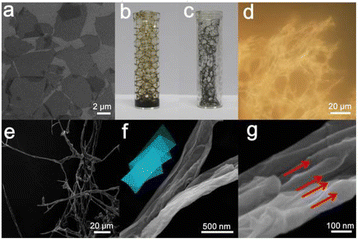
FGBs were prepared from flat GO sheets ranging in size from ca. 2 to 5 μm (Fig. 1a) with a thickness of about 0.93 nm (Fig. S1†) The negatively charged oxygen-containing species on the surface make GO a dispersible carbon nanomaterial with zeta potential as low as −43 mV in water. As a result, the GO dispersion is considered a good precursor for versatile fabrication and assembly of different types of graphene-based architectures.14–16 In order to create stable air bubbles, polyoxypropylenediamine (e.g. D400) was employed as a surfactant.17 The surface tension (Fig. S2†) of the GO dispersion dropped dramatically from 71 to 44 mN m−1 in the presence of D400 at a GO concentration of 3 mg mL−1. Stable air bubbles were formed in the GO/D400 mixture solution by blowing compressed air into the solution (Fig. 1b). In comparison, control experiments have shown that neither the GO dispersion nor D400 solution could form stable air bubbles alone (data not shown).
Interestingly, the thin aqueous GO films surrounding the air bubbles were readily transformed into macroscopic fibrous networks after shock cooling followed by a freeze drying process (Fig. 1c). The digital image (Fig. 1d) of the product features a macroscopic fibrous configuration. The corresponding optical and SEM images reveal that flat GO nanosheets are transformed into a 1D fibrous structure that extends as long as 100 μm (Fig. 1e and f). The yield of the fibrous structure was calculated to be 56.3%. Given that the size of a pristine GO nanosheet is only a few micrometers, one strip of the fibrous structure is likely made up of several GO nanosheets. Analysis of high magnification SEM images leads one to believe that the GO fiber possesses a structure of compact nanobelts possibly formed by zig-zag folding of flat GO nanosheets (Fig. 1f and g). The inset of Fig. 1f illustrates a proposed schematic structure of the FGOBs. The corresponding parallel lines marked in Fig. 1g represent the folding axes of GO sheets during the folding process.
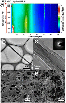
The FGOBs were readily transformed into folded graphene belts (FGBs) upon annealing. The transformation from FGOBs into FGBs was evidenced by in situ XRD (Fig. 2a). Originally, the FGOBs feature a peak at 2θ = 5°, corresponding to the intercalation of D400 into the interlayer space of the folded GO structure.6 The color scale highlights that the decrease in the low angle peak (∼5°) was accompanied by an increase in the typical graphene peak at ∼25° when temperature gradually increased to about 400 °C. The XRD patterns of the FGBs remained unchanged when temperature increased above 480 °C indicating the formation of stable FGBs. Therefore, the annealing of the FGOBs was performed under a N2 atmosphere at 500 °C with a heating rate of 1 °C min−1. The corresponding FTIR spectra show that the functional groups on the surface of FGOBs have been removed after annealing (Fig. S3†). More importantly, XPS measurement suggests that D400 can also serve as the N source to produce N-doped FGBs during the annealing process (Fig. S4†). TEM images of a typical FGB strip feature compact nanobelt structures (Fig. 2b and c). The selected area electron diffraction (SAED) pattern indicates the multicrystalline nature of the synthesized FGBs (inset image in Fig. 2c). The edge of a FGB shows face-to-face stacking of the graphene layers (Fig. S5†) that may be formed upon the folding process. The morphology of this 1D folded structure is different from that of previously discovered carbon nanoscrolls (CNSs) or graphene nanoscrolls (GNSs).12,18 This FGB has a compact belt structure that features an accordion-like geometry without a tubular inner hollow structure.
In our experiments, the folding process was carried out in a confined space (i.e., thin aqueous GO films formed between air bubbles). It is proposed that the flat GO sheets in the water film are forced to fold by the anisotropic growth of ice crystals. Initially, numerous small holes are created on the surface of the GO films due to homogeneous nucleation19 of water (Fig. 2d). Meanwhile, some belt structures can be identified at the boundaries of the holes (Fig. S6†). The final FGOBs are formed as the ice crystal domains meet with each other, where the flat GO layers between the ice crystals are squeezed into compact belts (Fig. 2e). The ice crystal guided folding of flat GO sheets can be further understood with the assistance of Video S1,† which vividly shows the anisotropic growth of ice in a confined space between two glass slides by polarized optical microscopy (POM).20 Fig. S7† is a snapshot captured from Video S1.† It reveals that ice crystals grow in a specific direction (Fig. S7a–c†). We propose that as the ice crystals grow in an aligned pattern (Fig. S7d–i†), GO sheets may be trapped between neighboring ice crystals eventually being squeezed into the final compact belt conformations in the manner of an accordion fold.
In addition to D400, three types of surfactants were also investigated to prove the mechanism of the ice crystal guided folding strategy. As demonstrated in Fig. S8a,† GO mixed with either an anionic surfactant (sodium dodecyl benzene sulfonate, SDBS) or a nonionic surfactant (polyvinyl alcohol 1788, PVA 1788) can form stable air bubbles. However, precipitation phenomena occurred when a cationic surfactant (cetyl trimethyl ammonium bromide, CTAB) was added into the GO dispersion (Fig. S8b†). Fig. S8c† demonstrates that SDBS or PVA 1788 can reduce the surface tension of the GO dispersion dramatically. Subsequent shock cooling of the GO air bubbles formed by GO/SDBS (Fig. S8d†) or GO/PVA1788 (Fig. S8e†) in liquid nitrogen can also result in lots of FGOBs.
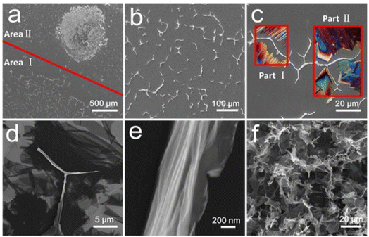
The critical role of a confined space can be further illustrated by the following control experiments. As illustrated in Fig. S9,† a thin layer of GO dispersion was created in a confined space generated between two Si wafers (area I). For comparison, a free GO droplet was placed on the surface of the same wafer as the reference (area II). Subsequently, the wafers were immersed into liquid nitrogen. Fig. 3 shows the overview of the Si substrate after freeze drying, where two totally different surface morphologies were observed. In the confined space (area I), the growth of ice crystals was restricted by the silicon wafers, and as a result, GO sheets were forced to fold into intertwined 1D belts (Fig. 3b). The shape of the GO nanobelts is potentially a result of different orientations of the ice crystals inducing the folding of GO sheets. Conceptually, this is shown in Fig. 3c, where the POM images of different ice crystals have been superimposed on the SEM image, demonstrating how the observed orientation may have been formed (insets part I and II in Fig. 3c). For example, part I in Fig. 3c may be formed by two ice crystal domains grown in opposite directions (as discussed in Fig. S6e and f†). Part II (Fig. 3c) was, however, likely to be created by three different crystal domains (as discussed in Fig. S5g–i†). Once compact belts were formed, they were almost perpendicular to the substrate due to the extrusion of ice crystals (Fig. S10a†). However, the detailed nanostructure of the as-prepared FGOBs is not clear by high magnification SEM imaging due to the poor electrical conductivity of GO (Fig. S10b†). Fig. 3d demonstrates the surface conformations of the Si wafer after annealing. It was found that a lot of partially folded graphene sheets were attached to the surface of the Si wafer, while the FGBs appeared with edges perpendicular to the surface of the wafer. Detailed surface morphology of the FGBs features the fan-folded configuration (Fig. 3e). In contrast, the uncovered area (area II) reveals a totally different result. Fig. 3f shows that the free GO droplet has been transformed into macroporous graphene assemblies as a result of the uncontrolled ice crystallization process. The SEM examination reveals that individual graphene sheets are randomly stacked together to form building blocks of a macroporous structure (Fig. S11a and b†), a typical pore configuration of graphene monoliths21 (or aerogels) that are formed in the freeze casting procedure.
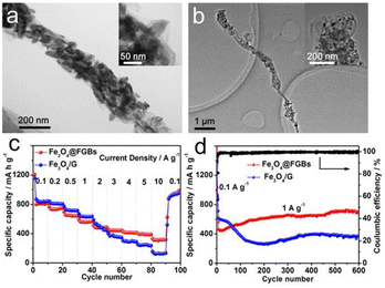
The ice crystal guided folding technique presented in this research also provides a facile approach to encapsulate functional nanomaterials into the FGBs. By adding specific nanoparticles into the starting GO dispersion containing D400, we successfully encapsulated Fe3O4 nanorods (Fig. 4a and S12a†), TiO2 (P25) (Fig. 4b and S12b†) and Co3O4 nanoparticles (Fig. S13†) into the 1D graphene structure. When used as anode materials for lithium-ion batteries, the Fe3O4@FGBs electrode exhibited superior rate capability and cycling performance over traditional Fe3O4/G composites (Fe3O4 loaded on graphene nanosheets). As shown in Fig. 4c, the Fe3O4@FGB electrode delivers capacities of about 390 mA h g−1 when tested at a high rate of 5 A g−1. Even at a higher rate of 10 A g−1, the reversible capacities still remain at approximately 324 mA h g−1, which is almost double the performance of the Fe3O4/G composite. Remarkably, the Fe3O4@FGBs electrode also retains a superior capacity of 702 mA h g−1 even after 600 cycles at a current rate of 1 A g−1, which is also much better than that of the Fe3O4/G composite. We propose that the fan-folding geometry can better accommodate the mechanical stress induced by the volume change of embedded Fe3O4 nanorods and thus maintain the structural and electrical integrity of the electrode during the charge and discharge processes. The preparation of this folded graphene structure may provide a new approach for rational design of high performance anode materials.
In summary, we have developed an ice crystal guided approach to the fabrication of FGBs in a confined space by initiating the folding of GO nanosheets. It has been found that the anisotropic growth of ice crystals confined by thin aqueous films surrounding air bubbles is the key to the directional folding of flexible 2D GO nanosheets into 1D nanobelts. Subsequently, the stable FGOBs were readily transformed into FGBs by annealing. The air bubble mediated folding process also provides a general approach to encapsulate active nanomaterials into FGBs thus resulting in functional FGBs for specific applications, such as energy storage and conversion. Our findings not only offer a new insight into the freeze casting technology, but also provide a novel methodology to control the morphological deformations of 2D graphene sheets with tuned flexible structures and wide applications in a number of fields such as energy storage.
Author contributions
W. B. Wan, X. J. Hao and Z. B. Zhao discovered the folded graphene oxide structure and made all the samples. W. B. Wan, T. C. Hughes and J. S. Qiu conceived and designed the experiments. X. J. Hao, T. C. Hughes and J. S. Qiu supervised the project. S. H. Liu conducted the Li-ion battery tests. W. B. Wan and X. J. Hao contributed to the in situ XRD and TEM characterization studies respectively. S. H. Liu contributed to the SEM characterization. All authors contributed to the manuscript preparation.Conflicts of interest
There are no conflicts of interest to declare.Acknowledgements
This work was supported by the Hainan Province Science and Technology Special Fund (ZDYF2022GXJS004), Deep Sea Technology Industry Promotion Project (DSTIC-CYCJ-2022004), Natural Science Foundation of China (22068012) and Natural Science Foundation of Hainan Province (221RC585,821MS0782, and 221MS048). The authors are thankful to Dr T. Gengenbach and Dr Fang Xia for assistance with the XPS and in situ XRD analysis. The authors acknowledge the National Geographic Society for permission to use and cite the video National Geographic: The Invisible World (TV 1979).Notes and references
- X. Y. Wang, S. Y. Liao, Y. J. Wan, P. L. Zhu, Y. G. Hu, T. Zhao, R. Sun and C. P. Wong, J. Mater. Chem. C, 2021, 10, 44–72 RSC.
- J. L. Miao and T. T. Fan, Carbon, 2023, 202, 495–527 CrossRef CAS.
- Q. Q. Dou, T. Whatley, T. Syed, W. Wei and H. Wang, J. Mater. Chem. A, 2022, 10, 19211–19230 RSC.
- Z. H. Tang, S. L. Shen, J. Zhuang and X. Wang, Angew. Chem., Int. Ed., 2010, 49, 4603–4607 CrossRef CAS PubMed.
- H. Hu, Z. B. Zhao, W. B. Wan, Y. Gogotsi and J. S. Qiu, Adv. Mater., 2013, 25, 2219–2223 CrossRef CAS PubMed.
- W. B. Wan, L. L. Li, Z. B. Zhao, H. Hu, X. J. Hao, D. A. Winkler, L. C. Xi, T. C. Hughes and J. S. Qiu, Adv. Funct. Mater., 2014, 24, 4915–4921 CrossRef CAS.
- X. Y. Zhu, C. Yang, P. W. Wu, Z. Q. Ma, Y. Y. Shang, G. Z. Bai, X. Y. Liu, G. Chang, N. Li, J. J. Dai, X. T. Wang and H. L. Zhang, Nanoscale, 2020, 12, 4882–4894 RSC.
- Z. Xu and C. Gao, Nat. Commun., 2011, 2, 571 CrossRef PubMed.
- H. Zhai, L. Xu, Z. Liu, L. Jin, Y. Yi, J. Zhang, Y. Fan, D. Cheng, J. Li, X. Liu, Q. Song, P. Yue and Y. Li, Chem. Eng. J., 2022, 439, 135502 CrossRef CAS.
- J. Y. Luo, H. D. Jang, T. Sun, L. Xiao, Z. He, A. P. Katsoulidis, M. G. Kanatzidis, J. M. Gibson and J. X. Huang, ACS Nano, 2011, 5, 8943–8949 CrossRef CAS PubMed.
- S. Mao, Z. H. Wen, H. Kim, G. H. Lu, P. Hurley and J. H. Chen, ACS Nano, 2012, 6, 7505–7513 CrossRef CAS PubMed.
- L. M. Viculis, J. J. Mack and R. B. Kaner, Science, 2003, 299, 1361 CrossRef CAS PubMed.
- W. B. Wan, Z. B. Zhao, H. Hu, X. J. Hao, T. C. Hughes, H. Ma, L. J. Pan and J. S. Qiu, Carbon, 2014, 76, 46–53 CrossRef CAS.
- S. Zhai and Y. Chen, Acc. Mater. Res., 2022, 3, 922–934 CrossRef CAS.
- N. B. Mohamed, M. F. El-Kady and R. B. Kaner, Adv. Funct. Mater., 2022, 32, 2203101 CrossRef CAS.
- P. He, T. Du, K. R. Zhao, J. Q. Dong, Y. S. Liang and Q. Q. Zhang, Adv. Mater., 2023, 35, 2208562 CrossRef CAS PubMed.
- W. B. Wan, Z. B. Zhao, T. C. Hughes, B. Q. Qian, S. H. Peng, X. J. Hao and J. S. Qiu, Carbon, 2015, 85, 16–23 CrossRef CAS.
- T. Shi, Y. Yao, Y. Li, S. T. Lu, W. Qin and X. H. Wu, Chem. Eng. J., 2023, 455, 140683 CrossRef CAS.
- X. Xie, Y. L. Zhou, H. C. Bi, K. B. Yin, S. Wan and L. T. Sun, Sci. Rep., 2013, 3, 2117 CrossRef PubMed.
- R. Basehart, W. Goldstein, B. Munster, D. J. Eagle and A. Pomansanof, DVD, 1979 Search PubMed.
- G. H. Yang, X. F. Zhang, R. J. Wang, X. Liu, J. M. Zhang, L. Zong and H. S. Yang, Mater. Horiz., 2023, 10, 1865–1874 RSC.
Footnote |
| † Electronic supplementary information (ESI) available: Video showing the formation of ice crystals, the surface tension measurement, FTIR, XPS and XRD spectra, additional SEM and TEM images, and snapshots of the ice crystallization process. See DOI: https://doi.org/10.1039/d3na00995e |
| This journal is © The Royal Society of Chemistry 2024 |


