 Open Access Article
Substrate deformability and applied normal force are coupled to change nanoscale friction
Zhaoyang
Yu
 a,
Mengyuan
Huang
*ab and
Xianren
Zhang
*a
aState Key Laboratory of Organic-Inorganic Composites, Beijing University of Chemical Technology, 100029 Beijing, China. E-mail: zhangxr@buct.edu.cn
bInstitute of Fluid Dynamics, Helmholtz-Zentrum Dresden-Rossendorf, 01328 Dresden, Germany. E-mail: m.huang@hzdr.de
First published on 26th July 2024
Abstract
Amonton's law of friction states that the friction force is proportional to the normal force in magnitude, and the slope gives a constant friction coefficient. In this work, with molecular dynamics simulation, we study how the kinetic friction at the nanoscale deviates qualitatively from the relation. Our simulation demonstrates that the friction behavior between a nanoscale AFM tip and an elastic graphene surface is regulated by the coupling of the applied normal force and the substrate deformability. First, it is found that the normal load-induced substrate deformation could lower friction at low load while increasing it at high load. In addition, when the applied force exceeds a certain threshold another abrupt change in friction behavior is observed, i.e., the stick–slip friction changes to the paired stick–slip friction. The unexpected change in friction behavior is then ascribed to the change of the microscopic contact states between the two surfaces: the increase in normal force and the substrate deformability together lead to a change in the energy landscape experienced by the tip. Finally, the Prandtl–Tomlinson model also validates that the change in friction behavior can be interpreted in terms of the energy landscape.
Introduction
Friction is a primary source of energy dissipation.1,2 How to control the friction behavior of interfaces has always been one of the major concerns in modern engineering.3–6 At a given normal force (pressure), relative parallel motion between the surfaces would generate friction, which acts parallel to the interface of two contacting surfaces. However, it is still challenging to quantitatively predict the amount of friction for a specific pair of interfaces.7–9Amonton's law of friction states that the friction force is proportional to the magnitude of the normal force. The slope gives the coefficient of friction (COF), which is independent of the applied normal force, the contact area, the surface roughness, and the sliding velocity. Actually, the relation is only a first-order approximation of how friction works. Modern studies indicate that the kinetic friction also sensitively depends on the sliding velocity10–13 and small and even atomic scale defects.14–16 These studies have deepened our understanding of friction: friction is a complex interaction between surfaces that depends on the intrinsic properties of the contacting surfaces.17–20
Numerous experimental and theoretical data show non-linear dependence of friction with respect to the normal force. Atomic force microscopy (AFM),21–23 molecular dynamics (MD) simulations24–26 and DFT27–29 are commonly used to study the friction phenomenon at the nano-scale. When the scale of contacting surfaces decreases towards the nanoscale, the pressure-dependent friction shows qualitative deviations from Amonton's law and a diversity of unusual friction behaviors was observed.30–39 First principles calculation by Li et al.40 demonstrated the non-monotonic changes in interface friction with normal pressure of various two-dimensional layered materials. Vu et al.41 found a weak correlation between the friction coefficient and normal pressure of graphite under incommensurate friction. Calculations with density functional theory (DFT)42 showed that silicon carbide could produce interlayer covalent bonds under high normal pressure to increase friction. Despite the insightful studies mentioned above, we still have a rather limited understanding of why and how friction relates to normal force, particularly on the molecular scale.
In addition to the effects of exerted normal force, the investigation of friction between two-dimensional materials and the emergence of puckering effects have demonstrated the importance of substrate deformability in predicting friction forces.43–45 Experimental studies based on atomic force microscopy have also highlighted the impact of substrate deformability on nanoscale friction forces.32,46 In this work, in addition to the separate effect of pressure and deformation on friction, we will demonstrate that the two factors are in fact coupled in changing the friction behavior.
In this work, with molecular dynamics simulations we study the kinetic friction between a nanoscale AFM and an elastic graphene surface under different normal forces. First, we demonstrate separately the effect of pressure and deformation on the resulting friction. Furthermore, we found that the friction is regulated by the coupling of the applied normal force and the substrate deformability. The change in friction behavior is ascribed to the change of the microscopic contact states between the two surfaces: the increase in normal force and the substrate deformability together lead to a change in the energy landscape experienced by the tip, which serves as an indicator of microscopic contact states.
Models and simulation methods
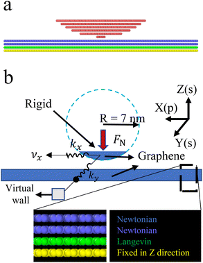
To mimic actual AFM friction experiments, we carried out molecular simulations on the sliding friction between a rigid spherical AFM tip and a 4-layer graphene surface. Fig. 1a shows the molecular model of the graphite AFM tip and that of the graphene substrate. The schematic diagram of the corresponding physical model for the kinetic friction between them is presented in Fig. 1b. The graphene substrate is composed of 4 layers, each having a size of 20 nm × 20 nm. The Z coordinates of the atoms in the bottom graphene layer were fixed, namely it is assumed to be rigid in the Z-direction, while the other layers are deformable under pressure. For the top layer, the atoms in the Y-boundary were fixed in the X direction, to keep the system stationary. The rigid tip is 7 nm in radius and 2 nm in height, with the bottom layer (the contacting layer) composed of 25 atoms.To simulate the AFM cantilever pulling the probe, a spring force was applied to the probe in the X-direction (motion direction). To prevent the probe from random movement in the Y-direction, a spring was fixed to a virtual wall along the y-direction. The stiffness coefficients for both spring forces were set to kX = kY = 11.2 N m−1. For the interaction between different beads, the C–C interaction within the graphene layer and within the graphite layer is described by the Tersoff potential,47 and the interlayer C–C interaction is given by the typical 6–12 Lennard Jones (LJ) potential with the LJ potential parameters ε = 3.73 meV and σ = 0.335 nm.
In this work, we investigated the resulting friction force of the probe under different normal forces Fn. In practice, the simulation was performed in two steps. First, a given normal force was applied to the probe for 1 ns, during which the system temperature was gradually increased from an initial temperature of 10 K to 298.15 K. In the second step the tip was pulled in the X direction at a constant spring speed of 5 m s−1 under the given normal force. The resulting friction force is measured after the motion of the probe reaches a quasi-stationary state. As shown before, the manner in which the thermostat is applied has a significant effect48 and therefore, in our simulations, the Langevin hot bath was used for the third layer of atoms on the bottom plate, while the Nose–Hoover thermostat was used for the remaining atoms. We used the LAMMPS code49 for calculations and Ovito50 for visualization.
Results and discussion
Normal force-dependent change in the coefficient of friction and the transition of friction modes
Our simulations show that at a given normal force, relative motion between the tip and the substrate would generate kinetic friction, which acts parallel to the interface of two contacting surfaces. Based on the simulation data, the friction force f and the coefficient of friction (COF) can be determined. The friction force f can be obtained by averaging the instantaneous friction force using . The instantaneous friction force at a given moment can be taken as the instant spring force with fi = Fspring = kX(vt − X), or alternatively, as the reaction force received by the probe against the substrate. The coefficient of friction can then be determined using μ = f/Fn.
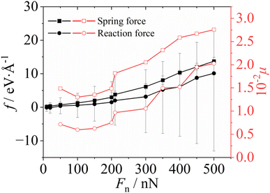
The calculated friction force and corresponding friction coefficient as a function of the normal pressure are shown in Fig. 2. The two methods give slightly different friction forces, but the same trend of the friction changing with the normal force is observed. This is because the force (spring force) acting on the probe is not strictly equal to the reaction force, and in general the reaction force acting on the tip caused by friction features large fluctuations. This phenomenon can be attributed to the fact that in comparison to the directed reaction, the exerted spring force is able to reduce the significant instantaneous friction force through storing spring potential energy. Fig. 2 also shows roughly how the friction coefficient (μ = f/Fn) changes with the normal force. It indicates that when Fn < 150 nN, the friction coefficient remained roughly constant or even decreased with an increase in normal load. As soon as Fn exceeded 150 nN, the friction coefficient clearly showed a positive correlation with the normal force.
Fig. 3 shows temporal evolution of the resulting friction force. The figure reveals that at small normal forces (Fn < 300 nN), the friction follows a stick–slip behavior (Fig. 3a and b) as expected,39 although the stick–slip behavior is smeared when Fn < 150 nN. However, as the pressure (or equivalently, the normal force) increases to 300 nN, the friction force–time (f–t) curve shows a “bimodal” behavior, namely a stick–slip process seems to split into a paired stick–slip process (Fig. 3c and d). The appearance of the paired stick–slip behavior coincides with the sudden increase in COF when Fn reaches 300 nN (see Fig. 2). Note that such paired stick–slip behavior cannot be clearly observed in the friction force–displacement (f–X) curve (see Fig. 4). This is because the paired stick-slip behavior featured a lengthened stick stage, which cannot be distinguished by the tip displacement. The two different stick–slip behaviors will be discussed in detail below.
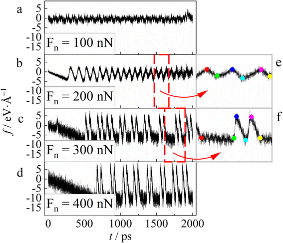 | ||
| Fig. 3 Friction force F varies with time under different normal forces, Fn = 100 (a), 200 (b), 300 (c), and 400 nN (d) from top to bottom, respectively. For Fn = 200 nN, several stick–slip cycles (see these enclosed by the gray dashed lines) are chosen and shown in a magnified picture (e). In the picture several typical configurations are chosen and represented by the symbol circles of various colors, which will be discussed in Fig. 4. For Fn = 300 nN, similarly, a particular paired stick–slip cycle is shown in picture (f), in which several configurations are denoted by the symbol circles of distinct colors. | ||
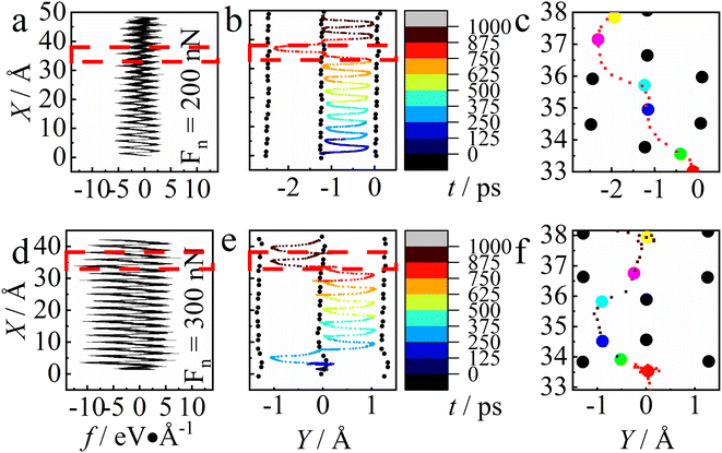 | ||
| Fig. 4 (a and d) Friction force vs. displacement. (b and e) The trajectory of the tip (rainbow color) and corresponding substrate atom (black). The colors of trajectory points represent the simulation time. The area surrounded by dashed lines was amplified and presented in (c and f). (a–c) Results of Fn = 200 nN and (d–f) of Fn = 300 nN. The colored dots in (c) and (f) correspond to those shown in Fig. 3e and f, one by one. Note that the region enclosed by grey dashed lines in figure represents the same range of data as that in Fig. 3, which are however visualized in different ways. | ||
The difference in the spatial and temporal features between the stick–slip and the paired stick–slip friction behaviors
The corresponding friction force–displacement curves are shown in Fig. 4a and d for Fn = 200 nN and 300 nN, respectively. The curves display similar shapes, and as expected the friction increases as the load increases to Fn = 300 nN. We recorded trajectories for Fn = 200 nN and 300 nN that range from t = 0 ns to 1 ns, with equal time intervals. In Fig. 4b and e we provide these trajectories respectively, using the variation of color to denote the time evolution that is shown in Fig. 3. In the figures the trajectory of the probe is denoted with small dots, which represent the projections of the center of mass position of the probe on the X–Y plane, while the large dots stand for the neighboring atoms of the substrate. Since the substrate atoms also move slightly during the simulation, we averaged the coordinates of the substrate atoms over time, with the procedure as follows. First, we selected the six substrate atoms that are closest to the center of mass of the probe (graphite plane structure) and recorded their coordinates sequentially during the whole stick stage. Then, for each substrate atom, its position that appeared in Fig. 4 was determined by averaging all recorded positions.At the smaller load (Fn = 200 nN), the stick–slip behavior in Fig. 3b corresponds to the particular type of trajectory evolution shown in Fig. 4b, in which the trajectory points are nearly evenly distributed, revealing that time and displacement evolve almost linearly. At Fn = 300 nN, however, the bimodal behavior appears, and the trajectory points show uneven distributions, demonstrating that not only the tip tends to stick at certain positions (Fig. 4e), but also the stick stage lasts a longer time. It is this long-term stick stage that causes the paired stick–slip (see Fig. 3f). The difference between the stick–slip behavior and the paired stick–slip behavior is clearly shown in Fig. 4c and f, which are the zoomed-in results from Fig. 4b and e, demonstrating that the paired stick–slip featured the lengthened stick stage. In the following, we will explain the origin of the pressure-driven transition in friction mode by analyzing three plausible reasons: the change of the actual contact area with the pressure, the pressure-induced substrate deformation, and the variation of the energy landscape detected by the tip due to coupling of the pressure and substrate deformability.
The microscopic mechanisms for the transition of friction modes
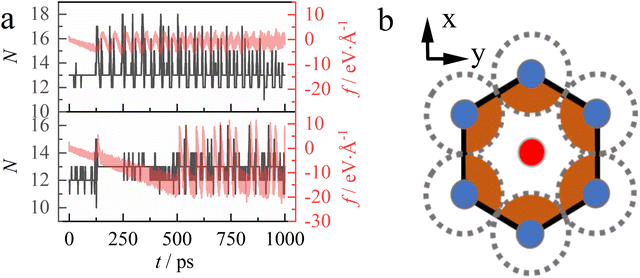
However, we find that the number of atoms in contact, and hence the real contact area, hardly change during the whole friction process, partly because of the exerted normal force. Here, we used a simplified criterion to determine whether the tip and substrate atoms are in contact: when a probe atom is embedded within the given region that encloses a substrate atom (see the orange area shown in Fig. 5b), they are considered to be in contact; otherwise, they are not in contact. Fig. 5a shows that there is no significant difference in the number of contacting atoms between the cases of Fn = 200 nN and Fn = 300 nN, which disproves the assumption that the contacting area changes with the load.
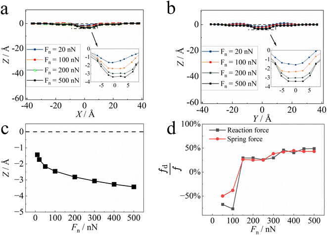
To investigate the effect of substrate deformation on the friction in more detail, we also simulated the friction between the AFM tip and a rigid substrate. In this set of simulation runs, other variables and parameters are the same as before except that the substrate was set to be rigid. The resulting friction frigid was again determined as a function of the normal force exerted. Through comparison with the friction from the elastic substrate f, the effect of substrate deformation on sliding friction can be described by fd = f − frigid. In Fig. 6d, we present fd/f as a function of the load. Overall, substrate deformability plays an important role in friction: the resulting ratio of friction change due to substrate deformation, fd/f, changes suddenly from −50% to 30% at Fn = 150 nN and then increases to ∼50% at Fn = 300 nN. The figure clearly indicates that at low load (Fn < 150 nN) the friction decreases as the substrate becomes deformable, but at high load (Fn ≥ 150 nN) the friction is enhanced by the substrate softness. This observation is consistent with the change in the friction coefficient with the increase in load (Fig. 2), namely, the friction coefficient remained roughly constant or even decreased when Fn < 150 nN, while it increased for Fn ≥ 150 nN.
The respective positive and negative contributions of substrate softness to the resulting friction can be interpreted as follows. Compared to the rigid substrate, the rather weak deformation of the soft substrates at low pressure would decrease the resistance to sliding and thus reduce the friction. At high pressure, however, the large deformation enhances and can reach a size comparable to that of the substrate atoms. The deformation zone thus makes the relative movement between the two surfaces more difficult. In this case, the net effect of surface deformation is thus to prevent, in a much more effective way, the two surfaces from relative movement.
However, substrate deformation seems not to be the determining factor causing the change in friction mode. This is because the abrupt change of the positive contribution of substrate deformation to a negative contribution occurs at a load of 150 nN, much less than the threshold needed for the transition in friction mode (Fn ≈ 300 nN).
Finally, we come to the third mechanism, namely the increase in normal force enables the tip to detect different energy landscapes of the substrate. This mechanism assumes that the tip will experience a different potential landscape when the normal force increases to a certain value, i.e., 300 nN in our case.
 . In total, 35 × 35 positions in the region were chosen. For each position where the x- and y-coordinates of the tip COM were fixed, an independent simulation run was performed, in which the tip moved slowly towards the substrate, until the equilibrium state of the whole system was reached at the given normal force Fn. In this process, the Nose Hoover thermostat was used for both the tip and the substrate at 0 K. After the tip reached its equilibrium position, we recorded the total interaction potential of the substrate exerted by the tip. After the potentials have been obtained for different positions at the given normal force, the relative potential energy landscape felt by the tip can be summarized.
Fig. 7d–f show the relative potential energy landscape felt by the tip under different normal forces, in the presence of both potential wells and potential barriers. As expected, we find that as the load increases, the depth of potential wells also increases. More interestingly, the shape of the energy landscape surface also changes when the normal force Fn increases from 200 nN to 300 nN. The figure shows that the position denoted by the pink square symbol, with a coordinate of  , is originally a potential well at a low pressure of 200 nN, but becomes a potential barrier at high pressures of 300 nN and 500 nN. In addition, all the positions atop the six substrate atoms (denoted by the star symbols that are located around the pink square symbol) correspond to potential barriers at low pressure, but three of them change to potential wells at higher pressures. The change in the energy landscape enhances the possibility of the tip sticking at certain positions as observed in Fig. 4f, which further leads to the occurrence of the paired stick–slip behavior and increases the friction coefficient.
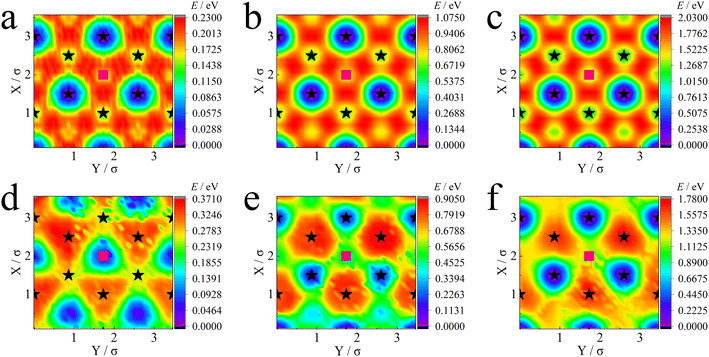 | ||
| Fig. 7 Energy landscape detected by the tip under different loads of Fn = 100 nN, 300 nN and 500 nN for a completely rigid (a–c) or deformable substrate (d–f). For the elastic substrate (d–f), when the exerted normal force increases from 200 nN to 300 nN, a different type of landscape appears, corresponding to the occurrence of the bimodal friction mode observed in Fig. 3. However, for a completely rigid substrate such a change in the energy landscape disappears. In this figure black stars represent the positions of substrate atoms and the pink square illustrates the center of the region enclosed by the six substrate atoms. | ||
In summary, the consistency in the transition of the friction mode and the energy landscape at 300 nN demonstrates that the change in the potential energy surface causes the change in the friction mode, which further leads to the varied coefficient of friction itself. Compared to cases under small pressure, the strong normal force compacts the contact between the tip and the deformable substrate, creating a more effective microscopic contact state. Therefore, it is the different contacting states that lead to the transition in the friction mode from the stick–slip behavior to paired stick–slip behavior. Importantly, the change in the energy landscape requires both high normal force and substrate deformability.
We note that the double stick–slip behavior may be a particular feature of the specific tip-sample system we studied, rather than a universal feature of nanoscale friction. However, its occurrence indeed indicates a shift in friction mechanisms: the synergistic effect between pressure and deformation alters the energy surface landscape, changes the contact state, and results in a transition in the friction mechanism.
Prandtl–Tomlinson model validates the load-induced change in the friction coefficient
To further validate the change in friction due to this energy surface change, we alternatively used the Prandtl–Tomlinson (PT) model51 to describe the friction behavior for the system we studied. Our total system energy Utot can then be written as | (1) |
In this work we employed the two-dimensional PT model by Dong et al.,52 in which the kinetic equations of the probe on a graphene substrate can be described by the Langevin equation,
 | (2) |
 ,53–56 and ξ(t) is the thermal fluctuation. To calculate the friction within the framework of the PT model, eqn (2) was solved in the procedure mentioned in ref. 41. First, we extracted the few major frequency basis functions from the discrete data obtained from the MD-determined E with the 2D Fourier transform. The basis functions corresponding to the first n terms of εi are then summed to obtain a continuous energy surface function E(X,Y) of the following form:
 | (3) |
Finally, with the fitted E(X,Y) we solved eqn (2) using the 4th order Runge–Kutta algorithm. With the obtained X(t) and Y(t), the friction is determined in a same way as in the molecular simulation. Fig. 8b and c give two typical f–t (v = 5 m s−1) curves calculated with the PT model, corresponding respectively to Fn = 200 nN and Fn = 500 nN. As expected, the typical stick–slip behavior is observed in both cases. From Fig. 8b and c we can see that the f–t (v = 5 m s−1) curve calculated using the PT model indeed changes as the pressure increases. Here, the case of Fn = 500 nN does not show the paired stick–slip phenomenon as in Fig. 3, and this may be due to the absence of the deformation of the bottom plate57,58 under friction in the PT model.
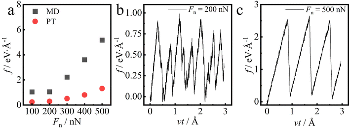 | ||
| Fig. 8 (a) Friction predicted by molecular dynamics simulation (black squares) vs. that predicted with the PT (red circles) model. The MD data here are the friction for the tip on the rigid substrate that was determined with the spring force method (the same data as in Fig. 6d). (b and c) The friction from the PT model as a function of displacement at (b) Fn = 200 nN and (c) Fn = 500 nN. | ||
The calculated friction as a function of pressure is summarized in Fig. 8a. As a comparison, the frictions from MD simulations are also shown in the figure. The comparison shows that although the two different methods give different friction forces, they predict a similar trend in load-dependent friction: the friction keeps almost constant at ≤200 nN, while the friction increases with pressure at higher load. This similarity indicates that the change in the friction behavior can indeed be interpreted in terms of the energy state. The deviation between the two methods (MD and PT model) shown in Fig. 8a may originate from the fact that in the PT model the friction is predicted based on the energy landscape surface obtained from the equilibrium MD calculations, e.g., Fig. 7, although the friction is non-equilibrium in nature. This could be the reason why the prediction of the PT model differs from that of the non-equilibrium MD simulations shown in Fig. 6d.
Conclusions
In this study, we performed MD simulations to investigate the molecular mechanism of pressure-driven change in kinetic friction at the nanoscale. To mimic the actual AFM friction experiments, we developed a molecular dynamics model for the friction between a nanoscale AFM tip and a smooth but elastic substrate formed by four graphene layers. Our simulation shows that the load-induced substrate deformation could lower friction at low load while increasing the friction at high load. In addition, a transition in the friction mode is observed from our simulation study as the normal force increases: after the exerted normal force reaches a threshold, the stick–slip friction abruptly changes to the paired stick–slip friction, accompanied by an increase in the coefficient of friction. The microscopic mechanism for such a transition, namely how it happens at the microscopic level, is discussed in detail.We analyzed the reasons for the increase in the friction coefficient and the transition in the friction model, from the perspective of the changes induced by enhanced pressure: the actual contact area, the substrate deformation and the energy landscape experienced by the tip. Our results show that the coupling of the applied normal force and the substrate deformability changes the microscopic contact states between the two nanoscale surfaces. In our case, when the applied force exceeds a certain threshold, the tip would experience a different energy landscape if the substrate is deformable, which thus leads to the change in friction mode. Finally, the Prandtl–Tomlinson model is used to validate the change in the friction coefficient, confirming that the change in the friction behavior can be interpreted in terms of the energy landscape. The molecular-scale insights from this study not only provide a new synergy mechanism to tune the nanoscale friction, but also provide the connection between friction behaviors and frictional contact states, which has the potential to be applied in various friction scenarios.
Data availability
The data that support the findings of this study are available from the corresponding author, Xianren Zhang, upon reasonable request.Conflicts of interest
There are no conflicts to declare.Acknowledgements
We would like to thank G. Mutschke for valuable discussions. Financial support from the National Natural Science Foundation of China (Grant No. 21978007 and 22278013), from the Helmholtz-OCPC Postdoc Program (grant no. ZD2022022) and from the Federal Ministry of Education and Research (BMBF) within the project H2Giga-SINEWAVE, grant no. 03HY123E, is greatly acknowledged.References
- A. Buldum, D. M. Leitner and S. Ciraci, Model for phononic energy dissipation in friction, Phys. Rev. B: Condens. Matter Mater. Phys., 1999, 59, 16042–16046 CrossRef CAS.
- A. I. Volokitin and B. N. J. Persson, Quantum Friction, Phys. Rev. Lett., 2011, 106, 094502 CrossRef CAS PubMed.
- C. Liu, O. Friedman, Y. Meng, Y. Tian and Y. Golan, CuS Nanoparticle Additives for Enhanced Ester Lubricant Performance, ACS Appl. Nano Mater., 2018, 1, 7060–7065 CrossRef CAS.
- Y. Zhou and J. Qu, Ionic Liquids as Lubricant Additives: A Review, ACS Appl. Mater. Interfaces, 2017, 9, 3209–3222 CrossRef CAS.
- H. L. Costa, J. Schille and A. Rosenkranz, Tailored surface textures to increase friction—A review, Friction, 2022, 10, 1285–1304 CrossRef.
- J. Luo, M. Liu and L. Ma, Origin of friction and the new frictionless technology—Superlubricity: Advancements and future outlook, Nano Energy, 2021, 86, 106092 CrossRef CAS.
- A. Levent Demirel and S. Granick, Friction Fluctuations and Friction Memory in Stick-Slip Motion, Phys. Rev. Lett., 1996, 77, 4330–4333 CrossRef CAS.
- M. Hirano and K. Shinjo, Atomistic locking and friction, Phys. Rev. B: Condens. Matter Mater. Phys., 1990, 41, 11837–11851 CrossRef CAS PubMed.
- E. D. Smith, M. O. Robbins and M. Cieplak, Friction on adsorbed monolayers, Phys. Rev. B: Condens. Matter Mater. Phys., 1996, 54, 8252–8260 CrossRef CAS.
- E. Gnecco, R. Bennewitz, T. Gyalog, Ch. Loppacher, M. Bammerlin, E. Meyer and H.-J. Güntherodt, Velocity Dependence of Atomic Friction, Phys. Rev. Lett., 2000, 84, 1172–1175 CrossRef CAS.
- Z. Duan, Z. Wei, S. Huang, Y. Wang, C. Sun, Y. Tao, Y. Dong, J. Yang, Y. Zhang, Y. Kan, D. Li and Y. Chen, Resonance in Atomic-Scale Sliding Friction, Nano Lett., 2021, 21, 4615–4621 CrossRef CAS.
- Z. Wei, Z. Duan, Y. Kan, Y. Zhang and Y. Chen, Phonon energy dissipation in friction between graphene/graphene interface, J. Appl. Phys., 2020, 127, 015105 CrossRef CAS.
- O. M. Braun and M. Peyrard, Dependence of kinetic friction on velocity: Master equation approach, Phys. Rev. E: Stat., Nonlinear, Soft Matter Phys., 2011, 83, 046129 CrossRef CAS.
- A. Seal and A. Govind Rajan, Modulating Water Slip Using Atomic-Scale Defects: Friction on Realistic Hexagonal Boron Nitride Surfaces, Nano Lett., 2021, 21, 8008–8016 CrossRef CAS PubMed.
- J. B. Sokoloff, Effects of defects on the friction between film and substrate in a microbalance experiment, Phys. Rev. B: Condens. Matter Mater. Phys., 1995, 51, 15573–15574 CrossRef.
- J. J. Bikerman, Surface Roughness and Sliding Friction, Rev. Mod. Phys., 1944, 16, 53–68 CrossRef.
- D. L. Goldsby and T. E. Tullis, Low frictional strength of quartz rocks at subseismic slip rates, Geophys. Res. Lett., 2002, 29, 25 CrossRef.
- H. Sakuma, Adhesion energy between mica surfaces: Implications for the frictional coefficient under dry and wet conditions, J. Geophys. Res.: Solid Earth, 2013, 118, 6066–6075 CrossRef.
- M. Chandross and N. Argibay, Friction of Metals: A Review of Microstructural Evolution and Nanoscale Phenomena in Shearing Contacts, Tribol. Lett., 2021, 69, 119 CrossRef CAS.
- B. K. Yen, B. E. Schwickert and M. F. Toney, Origin of low-friction behavior in graphite investigated by surface x-ray diffraction, Appl. Phys. Lett., 2004, 84, 4702–4704 CrossRef CAS.
- H. Bluhm, T. Inoue and M. Salmeron, Friction of ice measured using lateral force microscopy, Phys. Rev. B: Condens. Matter Mater. Phys., 2000, 61, 7760–7765 CrossRef CAS.
- A. Labuda, M. Lysy, W. Paul, Y. Miyahara, P. Grütter, R. Bennewitz and M. Sutton, Stochastic noise in atomic force microscopy, Phys. Rev. E: Stat., Nonlinear, Soft Matter Phys., 2012, 86, 031104 CrossRef.
- Z. Ye, A. Balkanci, A. Martini and M. Z. Baykara, Effect of roughness on the layer-dependent friction of few-layer graphene, Phys. Rev. B, 2017, 96, 115401 CrossRef.
- S. Li, Q. Li, R. W. Carpick, P. Gumbsch, X. Z. Liu, X. Ding, J. Sun and J. Li, The evolving quality of frictional contact with graphene, Nature, 2016, 539, 541–545 CrossRef CAS PubMed.
- H. Mohammadi and M. H. Müser, Friction of Wrinkles, Phys. Rev. Lett., 2010, 105, 224301 CrossRef PubMed.
- G. Ru, W. Qi, Y. Wei, K. Tang and T. Xue, Superlubricity in bilayer isomeric tellurene and graphene/tellurene van der Waals heterostructures, Tribol. Int., 2021, 159, 106974 CrossRef CAS.
- H. Zhan, X. Tan, G. Xie and D. Guo, Reduced Fracture Strength of 2D Materials Induced by Interlayer Friction, Small, 2021, 17, 2005996 CrossRef CAS PubMed.
- W. Gao and A. Tkatchenko, Sliding Mechanisms in Multilayered Hexagonal Boron Nitride and Graphene: The Effects of Directionality, Thickness, and Sliding Constraints, Phys. Rev. Lett., 2015, 114, 096101 CrossRef.
- X. Cai, J. Wang, J. Li, Q. Sun and Y. Jia, Spin friction between Co monolayer and Mn/W(110) surface: Ab Initio investigations, Tribol. Int., 2016, 95, 419–425 CrossRef CAS.
- J. Sun, Y. Zhang, Z. Lu, Q. Li, Q. Xue, S. Du, J. Pu and L. Wang, Superlubricity Enabled by Pressure-Induced Friction Collapse, J. Phys. Chem. Lett., 2018, 9, 2554–2559 CrossRef CAS.
- J. Gao, W. D. Luedtke, D. Gourdon, M. Ruths, J. N. Israelachvili and U. Landman, Frictional Forces and Amontons' Law: From the Molecular to the Macroscopic Scale, J. Phys. Chem. B, 2004, 108, 3410–3425 CrossRef CAS.
- Z. Deng, A. Smolyanitsky, Q. Li, X.-Q. Feng and R. J. Cannara, Adhesion-dependent negative friction coefficient on chemically modified graphite at the nanoscale, Nat. Mater., 2012, 11, 1032–1037 CrossRef CAS.
- Z. Liu, The diversity of friction behavior between bi-layer graphenes, Nanotechnology, 2014, 25, 075703 CrossRef CAS.
- E. Thormann, Negative friction coefficients, Nat. Mater., 2013, 12, 468 CrossRef CAS PubMed.
- B. Luan and M. O. Robbins, The breakdown of continuum models for mechanical contacts, Nature, 2005, 435, 929–932 CrossRef CAS PubMed.
- Y. Mo, K. T. Turner and I. Szlufarska, Friction laws at the nanoscale, Nature, 2009, 457, 1116–1119 CrossRef CAS.
- X.-Y. Sun, Y.-Z. Qi, W. Ouyang, X.-Q. Feng and Q. Li, Energy corrugation in atomic-scale friction on graphite revisited by molecular dynamics simulations, Acta Mech. Sin., 2016, 32, 604–610 CrossRef.
- L. Gao, Y. Ma, Y. Liu, A. Song, T. Ma, Y. Hu, Y. Su and L. Qiao, Anomalous Frictional Behaviors of Ir and Au Tips Sliding on Graphene/Ni(111) Substrate: Density Functional Theory Calculations, J. Phys. Chem. C, 2017, 121, 21397–21404 CrossRef CAS.
- M. C. Righi and M. Ferrario, Pressure Induced Friction Collapse of Rare Gas Boundary Layers Sliding over Metal Surfaces, Phys. Rev. Lett., 2007, 99, 176101 CrossRef CAS PubMed.
- H. Li, W. Shi, Y. Guo and W. Guo, Nonmonotonic interfacial friction with normal force in two-dimensional crystals, Phys. Rev. B, 2020, 102, 085427 CrossRef CAS.
- C. C. Vu, S. Zhang, M. Urbakh, Q. Li, Q.-C. He and Q. Zheng, Observation of normal-force-independent superlubricity in mesoscopic graphite contacts, Phys. Rev. B, 2016, 94, 081405 CrossRef.
- B. Szczefanowicz, T. Kuwahara, T. Filleter, A. Klemenz, L. Mayrhofer, R. Bennewitz and M. Moseler, Formation of intermittent covalent bonds at high contact pressure limits superlow friction on epitaxial graphene, Phys. Rev. Res., 2023, 5, L012049 CrossRef CAS.
- C. Lee, Q. Li, W. Kalb, X.-Z. Liu, H. Berger, R. W. Carpick and J. Hone, Frictional Characteristics of Atomically Thin Sheets, Science, 2010, 328, 76–80 CrossRef CAS PubMed.
- C. Xu, S. Zhang, H. Du, T. Xue, Y. Kang, Y. Zhang, P. Zhao and Q. Li, Revisiting Frictional Characteristics of Graphene: Effect of In-Plane Straining, ACS Appl. Mater. Interfaces, 2022, 14, 41571–41576 CrossRef CAS.
- M. Tripathi, F. Awaja, G. Paolicelli, R. Bartali, E. Iacob, S. Valeri, S. Ryu, S. Signetti, G. Speranza and N. M. Pugno, Tribological characteristics of few-layer graphene over Ni grain and interface boundaries, Nanoscale, 2016, 8, 6646–6658 RSC.
- Q. Li, C. Lee, R. W. Carpick and J. Hone, Substrate effect on thickness-dependent friction on graphene, Phys. Status Solidi B, 2010, 247, 2909–2914 CrossRef CAS.
- L. Lindsay and D. A. Broido, Optimized Tersoff and Brenner empirical potential parameters for lattice dynamics and phonon thermal transport in carbon nanotubes and graphene, Phys. Rev. B: Condens. Matter Mater. Phys., 2010, 81, 205441 CrossRef.
- J. Tao, X. Song, W. Chen, S. Zhao and H. Liu, Thermostat effect on water transport dynamics across CNT membranes, Mol. Simul., 2020, 46, 699–705 CrossRef CAS.
- S. Plimpton, Fast Parallel Algorithms for Short-Range Molecular Dynamics, J. Comput. Phys., 1995, 117, 1–19 CrossRef CAS.
- A. Stukowski, Visualization and analysis of atomistic simulation data with OVITO–the Open Visualization Tool, Modell. Simul. Mater. Sci. Eng., 2010, 18, 015012 CrossRef.
- L. Prandtl, Ein Gedankenmodell zur kinetischen Theorie der festen Körper, Z. Angew. Math. Mech., 1928, 8, 85–106 CrossRef.
- Y. Dong, A. Vadakkepatt and A. Martini, Analytical Models for Atomic Friction, Tribol. Lett., 2011, 44, 367–386 CrossRef CAS.
- Y. Sang, M. Dubé and M. Grant, Thermal Effects on Atomic Friction, Phys. Rev. Lett., 2001, 87, 174301 CrossRef CAS PubMed.
- C. Fusco and A. Fasolino, Velocity dependence of atomic-scale friction: A comparative study of the one- and two-dimensional Tomlinson model, Phys. Rev. B: Condens. Matter Mater. Phys., 2005, 71, 045413 CrossRef.
- M. Igarashi, A. Natori and J. Nakamura, Size effects in friction of multiatomic sliding contacts, Phys. Rev. B: Condens. Matter Mater. Phys., 2008, 78, 165427 CrossRef.
- P. Steiner, R. Roth, E. Gnecco, A. Baratoff, S. Maier, T. Glatzel and E. Meyer, Two-dimensional simulation of superlubricity on NaCl and highly oriented pyrolytic graphite, Phys. Rev. B: Condens. Matter Mater. Phys., 2009, 79, 045414 CrossRef.
- D. Andersson and A. S. De Wijn, Understanding the friction of atomically thin layered materials, Nat. Commun., 2020, 11, 420 CrossRef CAS.
- S. Zhang, Q. Yao, L. Chen, C. Jiang, T. Ma, H. Wang, X.-Q. Feng and Q. Li, Dual-Scale Stick-Slip Friction on Graphene/h − BN Moiré Superlattice Structure, Phys. Rev. Lett., 2022, 128, 226101 CrossRef CAS PubMed.
| This journal is © The Royal Society of Chemistry 2024 |

