 Open Access Article
Environmentally friendly PtNiCo nanocatalysts enhanced with multi-walled carbon nanotubes for sustainable methanol oxidation in an alkaline medium
Merve
Akin
ac,
Anas
El Attar
bd,
Ramazan
Bayat
ac,
Muhammed
Bekmezci
 ac,
Badr
Bouljoihel
b,
Mama
El Rhazi
b and
Fatih
Sen
 *ae
*ae
aSen Research Group, Department of Biochemistry, Dumlupinar University, Kutahya, Türkiye. E-mail: fatihsen1980@gmail.com
bLaboratory of Materials, Membranes, and Environment, Faculty of Science and Technology, University Hassan II of Casablanca, Morocco
cDepartment of Materials Science & Engineering, Faculty of Engineering, Dumlupinar University, Kutahya, Türkiye
dICGM, University of Montpellier, CNRS, ENSCM, 34095 Montpellier Cedex 5, France
eIncorporated Company, Kutahya Design & Technopole, Calca OSB Neighbourhood, 43100 Kutahya, Türkiye
First published on 16th September 2024
Abstract
In this study, trimetallic PtNiCo/MWCNT and PtNiCo catalysts were synthesized using a microwave method to reduce the amount of precious Pt. The prepared catalysts were characterized using XRD, TEM, and EDX mapping and their electrochemical performances for methanol oxidation were investigated. The results showed that the MWCNT-supported catalyst showed 2.42 times higher electrochemical activity than the PtNiCo catalyst with a peak current density of 283.14 mA cm−2 at −0.2 V potential. Moreover, in long-term stability tests, it exhibited high stability and 4.97 times higher current density at the end of 3600 s. The results showed that the MWCNT-supported catalyst offered improved electron transfer, 4.7 times higher surface area, and resistance to CO poisoning. These performance improvements due to the trimetallic structure are mostly thought to help accelerate the dehydrogenation of methanol. This study contains important findings for future functional catalyst design in the fields of catalysis and energy conversion.
1. Introduction
Today, the increasing energy demand brings along the search for alternative sources. At this point, fuel cells as a new-generation green energy have attracted attention as an alternative that can replace fossil fuel technology. Fuel cells are devices that convert chemical energy into electrical energy via electrochemical reaction, and there are different types of fuel cells.1–5 In particular, alcohol fuel cells have advantages such as easier transport, storage, cost-effectiveness and easy production of alcohol, which allow for the expansion fuel cell applications.6 Moreover, alcohol fuel cells have attracted more attention than hydrogen fuel cells owing to their high energy density.7–9 Among alcohol fuel cells, direct methanol fuel cells (DMFCs) are claimed to be particularly promising for portable devices, unmanned aerial vehicles and military applications.10 The increasing use of DMFCs is due to the easy use of methanol, operation at low temperatures, low emission rate and the ability to be used in portable systems.11,12 Therefore, the research on and applications of DMFCs have been increased. The basic reaction equations of DMFCs are shown below ((1)–(3)).13 As seen in the equations, electrochemical reactions of methanol and oxygen take place at the anode and cathode, respectively. Further, water and methanol react at the anode, releasing electrons, protons and CO2. Here, the catalyst accelerates the oxidation of methanol. Thus, it can be said that the efficiency of catalysts in methanol oxidation is greatly affected.| CH3OH + H2O → CO2 + 6H+ + 6e− (anode reaction) | (1) |
 | (2) |
CH3OH + ![[/]](https://www.rsc.org/images/entities/char_e0ee.gif) O2 → CO2 + 2H2O (overall reaction) O2 → CO2 + 2H2O (overall reaction) | (3) |
In DMFC applications, Pt,14,15 Pt group elements (Os,16 Ir,17 Rh,18 Ru,19,20 and Pd21), Au, and Ag22 elements are frequently preferred as catalysts.23,24 The high cost of these elements and problems such as CO poisoning on the Pt surface, particle aggregation and dissolution, and cell voltage loss due to methanol migration are the limitations for commercialization.25,26 Since CO has a great affinity for the Pt surface, small amounts of it can progressively occupy active sites, inhibit the adsorption of new reactants and eventually poison the Pt catalyst.27 To overcome these difficulties, significant efforts have been made to explore bimetallic,28,29 trimetallic30,31 or higher metal structures using transition metals alloyed with Pt to overcome the CO poisoning effect, reduce Pt loading, and improve MOR activity.32–35 Within the framework of this approach, platinum–nickel–cobalt (PtNiCo) alloy has attracted the most attention among many trimetallic catalysts due to its high CO tolerance in MOR.29,36 Recently, the use of support materials in catalysts37 has also attracted considerable attention, and it can be said that carbon-based materials give quite good results.38,39 In this study, MWCNT, one of the carbon-based materials, was used as a support material for the catalyst. MWCNTs have attracted attention due to their high surface area, high electron conductivity and superior mechanical strength and their use in fuel cell catalysts.40 It has also been reported that Pt-based nanomaterials supported with CNT provide higher electrocatalytic activity compared to other carbon derivatives.41,42 In addition, the high corrosion resistance and enhanced intrinsic catalytic activity of NiCo alloys have made them a highly effective electrocatalyst.43 Thus, PtNiCo/MWCNT particles were synthesized in this study as a catalyst with high performance and high electron transfer. Although platinum has high catalytic activity, it is known to be expensive and prone to poisoning.40 In the scope of this study, the tendency to poisoning and cost were reduced by adding Ni and Co. In addition, the use of NiCo can provide more active area on the Pt surface and improve the reaction mechanism. MWCNT provides a high surface area and better dispersion of catalyst nanoparticles. In this context, it can be said that the PtNiCo/MWCNT catalyst provides a good synergistic effect and increases the efficiency of methanol oxidation.
In this study, PtNiCo/MWCNT and PtNiCo catalysts were synthesized using the microwave method, which is a fast method. The obtained catalysts were characterized using XRD, EDX mapping, and TEM. The obtained catalysts were found to have high chemical stability and large surface area. The electro-oxidation of the electrocatalysts was investigated using cyclic voltammetry (CV), chronoamperometry (CA), linear sweep voltammetry (LSV), CO stripping, and electrochemical impedance spectroscopy (EIS) techniques. The results showed that the use of MWCNT as a support provides higher catalytic activity. The PtNiCo/MWCNT catalyst for direct methanol oxidation studies is reported for the first time in this study.
2. Materials & methods
Cobalt(II) chloride hexahydrate (CoCl2·6H2O), nickel(II) chloride hexahydrate (NiCl2·6H2O), platinum tetrachloride (PtCl4), potassium hydroxide (KOH), dimethylformamide (DMF), Nafion D-125, sulphuric acid (H2SO4), sodium hydroxide (NaOH), ethylene glycol, 2-propanol, MWCNT and nitric acid (HNO3) chemicals were used without any purification process. All chemicals were purchased from Sigma Aldrich. An X-ray diffractometer (XRD, Rigaku Miniflex), scanning electron microscope (SEM-EDX mapping) (JEOL JSM-5600LV), and transmission electron microscope (TEM-JEOL 1220) were used in the analyses.2.1. Synthesis of PtNiCo and PtNiCo/MWCNT electrocatalysts
PtNiCo and PtNiCo/MWCNT electrocatalysts used in methanol oxidation studies were synthesized using the microwave method. In this context, 50 mg MWCNT was added to 20 mL ethylene glycol and 5 mL 2-propanol mixture and dissolved with the help of a sonicator. To the homogenized solution, 10 mM PtCl4, 5 mM NiCl2·6H2O and 5 mM CoCl2·6H2O were added and stirred in a magnetic stirrer for 2 hours. After stirring, the pH of the solution was adjusted to 12 using 1 M NaOH. The mixture was irradiated in a kitchen microwave oven for 90 seconds. After cooling at room temperature, pH 4 was adjusted using 0.5 M HNO3. Finally, the formed PtNiCo/MWCNT nanoparticles were collected at 4000 rpm and washed several times with dH2O–ethanol mixture. Finally, they were dried in an oven at 50 °C for 24 hours. The same procedures were repeated for the synthesis of MWCNT-free PtNiCo.442.2. Electrochemical analysis
All electrochemical analyses were carried out with a potentiostat/galvanostat (Gamry Reference 3000). For electrochemical measurements, a classical three-electrode system was used. For the modification solution used in the study, 10 mg NP powder, 500 μL dH2O, 75 μL Nafion D-521 and 150 μL DMF were added. The ink was sonicated during 30 minutes in a bath filled with ice to maintain a low temperature. 10 μL of ink was deposited on the glassy carbon surface of the working electrode. The working electrode was dried for 20 min in an oven at 60 °C. Then, cycle voltammetry (CV), linear sweep voltammetry (LSV), chronoamperometry (CA), and electrochemical impedance spectroscopy (EIS) measurements were performed using a three-electrode system. Electrochemically active surface area (ECSA) studies were performed in 10 mM [Fe(CN)6]3−/4− medium containing 0.5 M KCl. Alcohol oxidation studies were carried out in the potential range from −0.8 V to 0.2 V in 1 M KOH solution containing 1 M CH3OH. Scan rate (SR) measurements were carried out at scan rates of 25 mV s−1, 50 mV s−1, 100 mV s−1, 150 mV s−1, and 250 mV s−1 in 1 M KOH solution containing 1 M CH3OH. Electrochemical impedance spectroscopy (EIS) measurements were also performed. EIS measurements were performed in 1 M KOH solution containing 1 M CH3OH at −0.35 V vs. Ag/AgCl in the frequency range from 10 kHz to 0.01 Hz. CO stripping voltammetry measurements were carried out between −0.2 and 1 V potentials at a scan rate of 25 mV s−1 after 15 min CO gas passage in 0.5 M H2SO4 medium.3. Results and discussion
3.1. Materials characterization
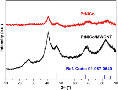
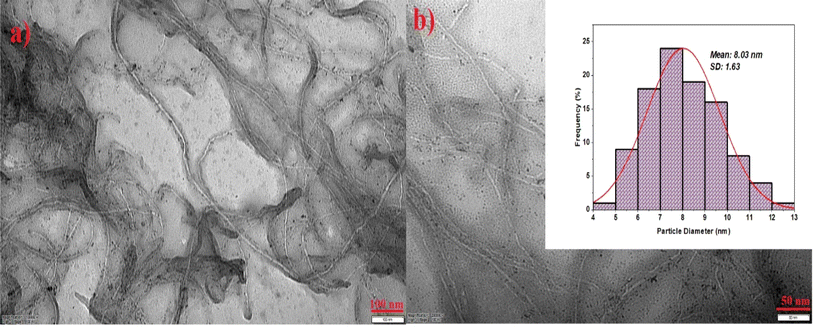
In the first step of the characterization of the electrocatalysts to be used in alcohol studies, XRD was used to determine the crystal structure of the electrocatalysts. The XRD patterns of PtNiCo and PtNiCo/MWCNT are shown in Fig. 1. PtNiCo (40.88°, 46.63°, 69.52°, 82.91°) and PtNiCo/MWCNT (40.81°, 46.6°. 68.63°, 82.31°) show the (111), (200), (220), and (311) planes of Pt with the surface-centered cubic (FCC) structure, respectively. Moreover, in the PtNiCo/MWCNT XRD diffraction, the peak at 26.24° indicates the C (002) plane. When compared with the reference code 01-087-0640, it is seen that there are shifts in the peaks.12,45 This shift is due to the presence of Ni and Co, which are smaller than Pt, indicating that the synthesis was completed and the PtNiCo alloy was realized.46 In addition, according to the XRD data, the diffraction peaks of Ni and Co cause significant changes in the peak intensities due to partial intersections. When the XRD peaks taken with and without support are examined, it is seen that the support in the catalyst creates some differences in the diffraction peaks. At this point, it can be said that the support provides an increase in the peak current densities, increases the degree of crystallinity and the narrower peaks give an idea that the crystal defects are reduced. The fact that no shift is observed for the peak indicates that the crystal structure of PtNiCo has not changed.After investigating the crystal structure, the morphological properties were determined using low magnification TEM. As seen in Fig. 2, PtNiCo nanoparticles were uniformly distributed. The deposition of the particles on the MWCNT surface creates a large surface area. All images show that the electrocatalyst samples are well dispersed without agglomeration.47 As clearly seen in the TEM images, almost spherical metal structures were observed on the MWCNT tubes. The particle size obtained because of the histogram was about 8 nm (Fig. 2b). For a trimetallic structure, this size was quite good compared to the literature. However, the SD value increased due to the trimetallic structure, suggesting that it is due to metal interactions that are not fully understood. Similarly, it was observed that the MWCNT structure retained its form quite well after synthesis. In this case, microwave synthesis is considered to be the main cause influencing the formal structure.
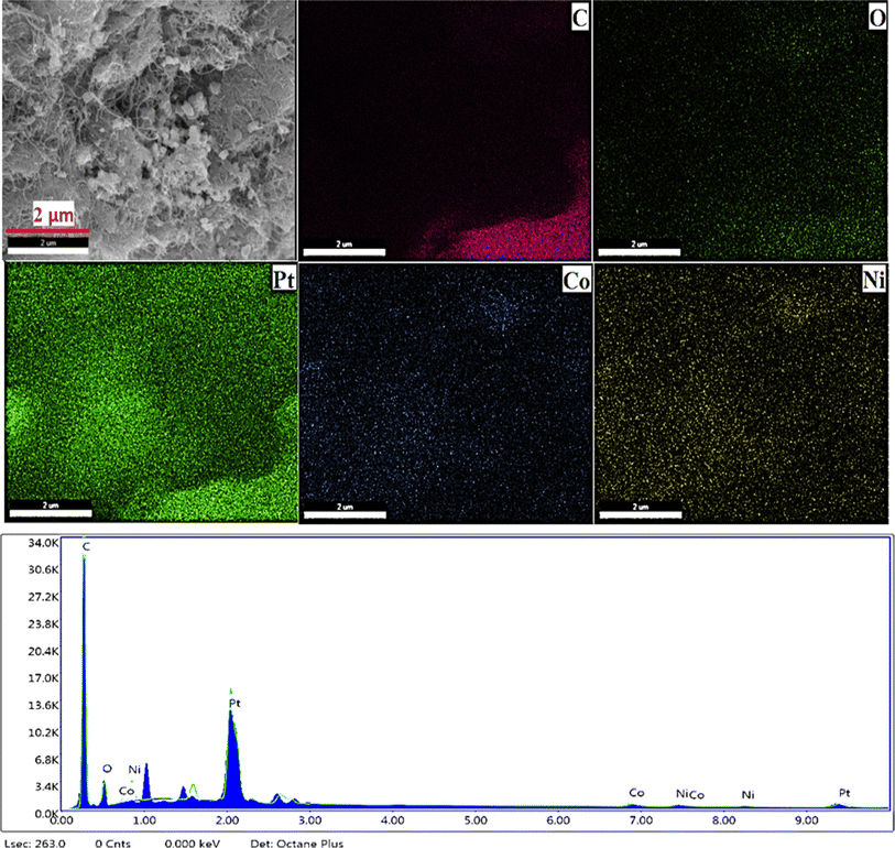
In addition, the EDX mapping of the PtNiCo/MWCNT catalyst obtained within the scope of the study was performed and is shown in Fig. 3. The presence and distribution of Pt, Ni, Co, and C in the catalyst obtained here are shown. In the results obtained, it is seen that C is dominant and spread over a large area. Pt, Ni, Co, and O are also homogeneously distributed on the surface. EDX mapping shows the presence of elements well integrated on the MWCNT surface with high surface area and high potential for catalytic activity.
To assess the impact of adding MWCNTs on the electrochemical characteristics of the modified PtNiCo, an electrochemical characterization was carried out. Therefore, the CVs PtNiCo and PtNiCo/MWCNTs were recorded in 0.5 M KCl solution containing 10 mM of [Fe(CN)6]3−/4−, as shown in Fig. 4.
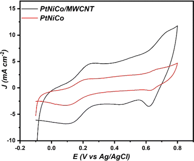 | ||
| Fig. 4 Cyclic voltammograms for PtNiCo/MWCNTs and PtNiCo in 10 mM [Fe(CN)6]3−/4− and 0.5 M KCl at 50 mV s−1. | ||
As can be seen, the PtNiCo present a current density value of about 1.73 mA cm−2 with a peak-to-peak separation (ΔEp) of about 0.181 V. After the introduction of MWCNT, we noticed that the value of current density of PtNiCo/MWCNT increased to 4.58 mA cm−2 with a decrease in the ΔEp value (0.12 V). This result supports the assertion made by many researchers that the presence of MWCNT enhanced the electronic transfer at the electrode surface.48,49
The electrochemical parameters of PtNiCo and PtNiCo/MWCNT are presented in Table 1.
| Electrode | I pa (mA cm−2) | I pc (mA cm−2) | E a (V) | E c (V) | ΔEp (V) |
|---|---|---|---|---|---|
| PtNiCo | 1.73 | −3.3 | 0.26 | 0.079 | 0.181 |
| PtNiCo/MWCNT | 4.58 | −6.67 | 0.24 | 0.124 | 0.116 |
The electrochemically active surface area (ECSA) of PtNiCo and PtNiCo/MWCNT was calculated using the Randles–Sevcik equation (eqn (4))50
| Ipa = (2.69 × 10⁵)n3/2AECSAD1/2Cν1/2 | (4) |
The electroactive surface area of PtNiCo/MWCNT is 0.329 cm2, which is 4.7 times higher than the electroactive surface area of PtNiCo (0.0694 cm−2). This result confirms that the introduction of MWCNT enhances the electroactive surface of the electrocatalyst, which lead to the improvement of their electrocatalytic activities.
3.2. Electrochemical studies
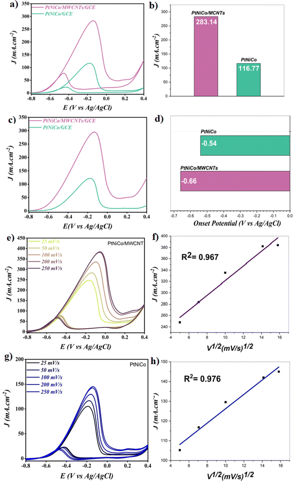
The primary goal is the oxidation of methanol in an alkaline solution; thus, cyclic voltammetry was used to examine how PtNiCo and PtNiCo/MWCNT react to the electrooxidation of methanol in a solution with 1 M methanol and 1 M KOH. The cyclic voltammograms performed at various electrocatalysts are displayed in Fig. 5a and the results are shown in the bar graph in Fig. 5b. As can be seen in Fig. 5a, PtNiCo/MWCNT showed a value of 283.14 mA cm−2, which is 2.42 times higher than that of PtNiCo (116.77 mA cm−2). The increased in the current density value of PtNiCo/MWCNT compared to PtNiCo is related to the presence of MWCNT, which led to a high adsorption capability of methanol on the surface due to their high surface area. Also, the presence of MWCNT increases the catalytic performance of the PtNiCo electrocatalyst toward methanol oxidation reaction (MOR).Another key parameter is the amount of (If/Ib), where If is the forward peak current density and Ib is the backward peak current density.51 A high value of If/Ib generally means that the poisoning of the electrode by the intermediate species is avoided. Table 2 summarizes the obtained results.
| Electrocatalysts | I f | I b | I f/Ib |
|---|---|---|---|
| PtNiCo/MWCNT | 283.14 | 77.68 | 3.64 |
| PtNiCo | 116.77 | 22.94 | 5.09 |
A value of (If/Ib) of 3.64 and 5.09 was obtained on PtNiCo/MWCNT and PtNiCo. The results shown suggest that throughout the methanol oxidation process, fewer species of intermediates were adsorbed on the catalyst. Also, these results gave an idea about CO poisoning in the structure.50 The obtained results conclude that both catalysts have very high CO tolerance. In addition, the LSV results obtained within the scope of the study (Fig. 5c and d) showed that the oxidation reaction of the PtNiCo/MWCNT structure started 1.2 times earlier than that of the PtNiCo catalyst. This result confirmed that the addition of MWCNT to the structure contributed to the formation of an easy and earlier oxidation reaction in the electrocatalyst surface compared to PtNiCo.
The scan rate experiments were also carried out for both electrocatalysts. Fig. 5e, f, g and h regroup the obtained results at PtNiCo/MWCNT and PtNiCo, respectively.
As can be seen, the value of current density increased with the increase in the scan rate value for both the electrocatalysts. This result indicates that a diffusion-controlled system was reached for both catalysts and the mass transfer was successfully achieved.52,53
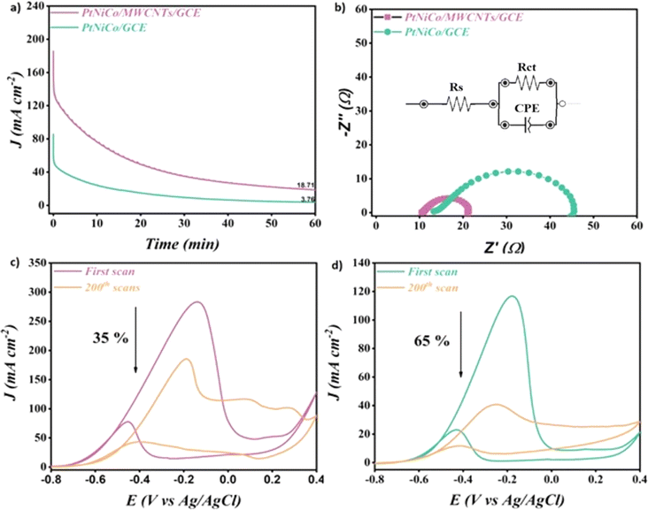
In order to confirm that the introduction of MWCNT increases the stability of the electrocatalysts, the chronoamperometric technique was performed in a solution containing 1 M KOH in the presence of 1 M CH3OH at −0.35 V vs. Ag/AgCl for 3600 s. Fig. 6a shows the obtained results for both the electrocatalysts. Both electrocatalysts exhibit a reduction in the current density from their peak values in the first few seconds, as can be seen. The adsorption of incomplete oxidation products onto the electrocatalyst surfaces may be the cause of this decline.54,55 It should be noted that the PtNiCo/MWCNT electrocatalyst reached a value of 18.71 mA cm−2 at 3600 s, which is 4.97 times higher than the value obtained by PtNiCo (3.76 mA cm−2). The presence of MWCNT led to the availability of a higher number of active sites on the surface of PtNiCo/MWCNT, which is the main reason behind this behavior.56,57
The electrochemical impedance spectroscopy (EIS) technique of PtNiCo/MWCNT and PtNiCo was performed in order to prove the role of MWCNT for the enhancement of the electrocatalytic activity of the electrocatalyst. Fig. 6b shows the obtained results of both the electrocatalysts. As mentioned in the literature, a small semicircle in the impedance graphs seen in the figure gives information about faster mass transfer.58 The PtNiCo/MWCNT presents a smaller semicircular diameter Rct (10 Ω) compared to PtNiCo (Rct = 35 Ω). This decrease in the Rct value after introducing MWCNT clearly demonstrates the ease of charge transfer at the surface of PtNiCo/MWCNT. This result is in agreement with the LSV results and showed that the faster reaction allowed the reaction to start at an earlier potential. The equivalent circuit compatible with the results is presented in the inset of Fig. 6b. In these circuits, Rs is the solution resistance, CPE is the constant phase element corresponding to the double layer capacitance and Rct is the charge transfer resistance associated with the oxidation of methanol.
The cyclic voltammetry technique with a high number of cycles is an important experiment to study the long-term stability of electrocatalysts towards methanol oxidation. Fig. 6c and d show the obtained results of PtNiCo/MWCNT and PtNiCo after cycling in methanol solution under 200 cycles. Both electrocatalysts present a decrease in the current density value with the increase in the cycle number. A loss of 35% of its initial current after 200 cycles was recorded for PtNiCo/MWCNT, which is 1.85 higher than that of PtNiCo (65%). This result indicates that the presence of MWCNT increases the stability of the electrocatalyst and avoids the poisoning of the surface of PtNiCo/MWCNT by the intermediate species during the MOR.
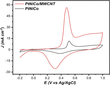
Finally, the behavior of both electrocatalysts in the presence of CO was electrochemically studied. CO stripping voltammetry measurements were carried out between potentials of −0.2 V vs. Ag/AgCl and 1 V vs. Ag/AgCl at a scan rate of 25 mV s−1 after 15 min CO gas evolution in 0.5 M H2SO4 medium. Fig. 7 shows the CV curves of PtNiCo and PtNiCo/MWCNT in 0.5 M H2SO4 saturated with CO.
From the results obtained, it is seen that the PtNiCo/MWCNT electrocatalyst presents the lowest value of the CO onset potential (0.27 V) and CO oxidation peak (0.47 V) compared to PtNiCo (CO onset potential is 0.41 V and the CO oxidation peak is 0.51 V). These results could be explained by the presence of MWCNT, which makes the PtNiCo/MWCNT electrocatalyst more tolerant to CO compared to the PtNiCo electrocatalyst.22,59,60
In Table 3, the electrocatalytic performance of PtNiCo and PtNiCo/MWCNT materials is compared to that of previously reported materials in the literature. This comparison shows that the trimetallic structures provide higher electrocatalytic activity compared to PtCo. It is also seen that the PtNiCo catalyst shows a very good synergistic effect. It can also be said that the carbon used as a support affects the electrocatalytic activity considerably.
| Electrocatalyst | Applied solution | Scan rate mV s−1 | Current density (mA cm−2) | Reference |
|---|---|---|---|---|
| Pt1Fe2@NC/MWCNT | 0.1 M HClO4 + 0.05 M CH3OH | 50 | 18.19 | 61 |
| Pt–Pd/RGO/GCE | 0.5 M H2SO4, 0.5 M CH3OH | 50 | 4.29 | 62 |
| PtCo@AC–VC | 1 M KOH + 1 M CH3OH | 50 | 73 | 44 |
| PtNi/rGO | 1 M KOH + 1 M CH3OH | 50 | 12.18 ± 0.36 | 63 |
| PtCo | 1 M KOH + 1 M CH3OH | 50 | 23.59 | 25 |
| PtNiCo | 1 M KOH + 1 M CH3OH | 50 | 116.77 | This work |
| PtNiCo/MWCNT | 1 M KOH + 1 M CH3OH | 50 | 283.14 | This work |
The results show that the PtNiCo/MWCNT catalyst provides significantly higher electrocatalytic activity compared to other electrocatalysts. These results confirm that our electrocatalysts could be considered as a good electrocatalyst for MOR in an alkaline medium.
4. Conclusion
It is known that research on electrocatalysts has a significant impact on energy efficiency. The high cost of platinum-based electrocatalysts and the lack of access to the source have led to the need to synthesize innovative catalysts. In particular, multi-metal nanoelectrocatalysts reveal important results in order to reduce the need for platinum. In this study, simple and efficient MWCNT-supported high-performance PtNiCo/MWCNT and PtNiCo were successfully synthesized by the microwave method. The results of various electrochemical measurements revealed that the PtNiCo/MWCNT-supported catalyst showed much higher catalytic activity, stability and durability in MOR. As a result of the PtNiCo/MWCNT electrocatalyst studies, an anodic peak current density 2.42 times higher than that of the PtNiCo electrocatalyst was obtained. As a result of the stability test, the use of the MWCNT support material resulted in a 4.97 times higher CA peak current density. CO stripping voltammetry study shows that PtNiCo/MWCNT is more tolerant to CO. According to the results obtained, reducing the need for platinum shows that catalysts with different structures and structures that can cover each other's shortcomings can be synthesized. The data obtained will lead to future fuel cell studies.Data availability
All data generated or analyzed during this study are included in this published article or are available from the corresponding author on reasonable request.Conflicts of interest
There are no conflicts to declare.Acknowledgements
R. Bayat is supported by the Council of Higher Education (CoHE) with 100/2000 PhD Scholarship and TUBITAK 2211-C. M. Bekmezci is supported by the TUBITAK 2211-C. The authors also would like to thank to DPU-BAP (2016-75; 2017-40 and 2018-29)References
- Y. Chandra Sekhar, P. Raghavendra, P. Sri Chandana, T. Maiyalagan and L. Subramanyam Sarma, J. Phys. Chem. Solids, 2023, 174, 111133 CrossRef CAS.
- M. Li, J. Shi, X. Guo, Y. Ying, Y. Wu, Y. Wen and H. Yang, J. Electroanal. Chem., 2023, 928, 117038 CrossRef CAS.
- M. M. Mohamed and A. A. Amer, J. Alloys Compd., 2023, 966, 171632 CrossRef CAS.
- M. Akin, M. Bekmezci, R. Bayat, I. Isik and F. Sen, Fuel, 2024, 357, 129771 CrossRef CAS.
- G. K. Kacmaz and N. Eczacioglu, Environ. Technol. Rev., 2024, 13, 76–95 CrossRef CAS.
- J. Zhang, S. Lu, Y. Xiang and S. P. Jiang, ChemSusChem, 2020, 13, 2484–2502 CrossRef CAS.
- D. M. Fadzillah, S. K. Kamarudin, M. A. Zainoodin and M. S. Masdar, Int. J. Hydrogen Energy, 2019, 44, 3031–3054 CrossRef CAS.
- M. Zhang, T. Zhou, D. Bukhvalov, F. Han, C. Wang and X. Yang, Appl. Catal., B, 2023, 337, 122976 CrossRef CAS.
- W. Jinxi, W. Aimin, A. K. Ghasemi, M. S. Lashkenari, E. Pashai, C. Karaman, D. E. Niculina and H. Karimi-Maleh, Fuel, 2023, 334, 126685 CrossRef.
- Z. Xia, X. Zhang, H. Sun, S. Wang and G. Sun, Nano Energy, 2019, 65, 104048 CrossRef CAS.
- S. Amirinejad and J. B. Parsa, Catal. Lett., 2024, 154, 1806–1818 CrossRef CAS.
- D. L. Quan, P. T. Hai, P. H. Le and D. N. Son, Res. Chem. Intermed., 2023, 49, 3987–4007 CrossRef CAS.
- S. S. Siwal, S. Thakur, Q. B. Zhang and V. K. Thakur, Mater. Today Chem., 2019, 14, 100182 CrossRef CAS.
- W. Zhang, X. Wang, M. Tan, H. Liu, Q. Ma, Q. Xu, B. G. Pollet and H. Su, Int. J. Hydrogen Energy, 2023, 48, 2617–2627 CrossRef CAS.
- Y. Wang, Z. Li, X. Zheng, R. Wu, J. Song, Y. Chen, X. Cao and Y. Nie, Appl. Catal., B, 2023, 325, 122383 CrossRef CAS.
- M. Bekmezci, G. N. Gules, R. Bayat and F. Sen, Anal. Methods, 2023, 15, 1223–1229 RSC.
- M. Bekmezci, D. B. Subasi, R. Bayat, M. Akin, Z. K. Coguplugil and F. Sen, New J. Chem., 2022, 46, 21591–21598 RSC.
- H. Liu, R. Jia, C. Qin, Q. Yang, Z. Tang, M. Li and Z. Ma, Adv. Funct. Mater., 2023, 33, 2210626 CrossRef CAS.
- R. Bayat, H. Burhan, M. Bekmezci, E. S. Isgin, M. Akin and F. Sen, Int. J. Hydrogen Energy, 2023, 48, 21128–21138 CrossRef CAS.
- G. V. Reddy, P. Raghavendra, B. Ankamwar, P. Sri Chandana, S. M. Senthil Kumar and L. S. Sarma, Mater. Chem. Front., 2017, 1, 757–766 RSC.
- F. Karimi, M. Akin, R. Bayat, M. Bekmezci, R. Darabi, E. Aghapour and F. Sen, Mol. Catal., 2023, 536, 112874 CrossRef CAS.
- H. Q. Pham and T. T. Huynh, Materials Advances, 2022, 3, 1609–1616 RSC.
- S. Belenov, A. Pavlets, K. Paperzh, D. Mauer, V. Menshikov, A. Alekseenko, I. Pankov, M. Tolstunov and V. Guterman, Catalysts, 2023, 13, 243 CrossRef CAS.
- Y. Zuo, W. Sheng, W. Tao and Z. Li, J. Mater. Sci. Technol., 2022, 114, 29–41 CrossRef CAS.
- R. Bayat, R. Darabi, Z. K. Coguplugil, M. Akin, M. Bekmezci, F. Sen and F. Karimi, Int. J. Hydrogen Energy, 2024, 52, 343–351 CrossRef CAS.
- F. Karimi, M. Akin, R. Bayat, M. Bekmezci, R. Darabi, E. Aghapour and F. Sen, Mol. Catal., 2023, 536, 112874 CrossRef CAS.
- W. Liao, S. Zhou, Z. Wang, F. Liu, J. Cao and Q. Wang, Fuel, 2022, 308, 122073 CrossRef CAS.
- Q. Lu, J. Li, K. Eid, X. Gu, Z. Wan, W. Li, R. S. Al-Hajri and A. M. Abdullah, J. Electroanal. Chem., 2022, 916, 116361 CrossRef CAS.
- F. Ma, R. Jin, K. Zhou, Y. Zhu, T. Huang, Q. Lu, L. Gai, L. Liu, R. S. Varma and K. Eid, Chem. Eng. J., 2024, 492, 151988 CrossRef CAS.
- Q. Lu, X. Gu, J. Li, W. Li, R. Luque and K. Eid, Ultrason. Sonochem., 2023, 98, 106494 CrossRef CAS PubMed.
- X. Luo, C. Liu, X. Wang, Q. Shao, Y. Pi, T. Zhu, Y. Li and X. Huang, Nano Lett., 2020, 20, 1967–1973 CrossRef CAS.
- C. Jiao, Z. Huang, X. Wang, H. Zhang, L. Lu and S. Zhang, RSC Adv., 2015, 5, 34364–34371 RSC.
- M. Yurderi, A. Bulut, M. Zahmakiran and M. Kaya, Appl. Catal., B, 2014, 160–161, 514–524 CrossRef CAS.
- Y. Chen, X.-X. Zheng, X.-Y. Huang, A.-J. Wang, Q.-L. Zhang, H. Huang and J.-J. Feng, J. Colloid Interface Sci., 2020, 559, 206–214 CrossRef CAS.
- C. K. Poh, Z. Tian, J. Gao, Z. Liu, J. Lin, Y. P. Feng and F. Su, J. Mater. Chem., 2012, 22, 13643 RSC.
- H. Huang, X. Hu, J. Zhang, N. Su and J. Cheng, Sci. Rep., 2017, 7, 45555 CrossRef CAS.
- A. Chalgin, C. Song, P. Tao, W. Shang, T. Deng and J. Wu, Prog. Nat. Sci.: Mater. Int., 2020, 30, 289–297 CrossRef CAS.
- Z. Teng, Z. Zhang and X. Li, Synth. Met., 2023, 293, 117256 CrossRef CAS.
- P. Salarizadeh, M. T. Tourchi Moghadam and M. B. Askari, Diamond Relat. Mater., 2023, 131, 109534 CrossRef CAS.
- F. Chen, J. Ren, Q. He, J. Liu and R. Song, J. Colloid Interface Sci., 2017, 497, 276–283 CrossRef CAS.
- M. Okamoto, T. Fujigaya and N. Nakashima, Small, 2009, 5, 735–740 CrossRef CAS PubMed.
- Q. Zhou, Y. An, S. Zhou, Z. Wang, J. Long, W. Liao, M. Chen and Q. Wang, J. Alloys Compd., 2023, 937, 168347 CrossRef CAS.
- F. Arshad, T. ul Haq, A. Khan, Y. Haik, I. Hussain and F. Sher, Energy Convers. Manage., 2022, 254, 115262 CrossRef CAS.
- H. Burhan, K. Arikan, M. H. Alma, M. S. Nas, H. Karimi-Maleh, F. Sen, F. Karimi and Y. Vasseghian, Int. J. Hydrogen Energy, 2023, 48, 6657–6665 CrossRef CAS.
- V. T. T. Phan, T. M. Pham, H. Q. Pham, T. T. Huynh, T. H. T. Nguyen and V. T. T. Ho, Int. J. Energy Res., 2022, 46, 19221–19232 CrossRef CAS.
- K.-Y. Shih, J.-J. Wei and M.-C. Tsai, Nanomaterials, 2021, 11, 2206 CrossRef CAS.
- W. Yuan, Y. Cheng, P. K. Shen, C. M. Li and S. P. Jiang, J. Mater. Chem. A, 2015, 3, 1961–1971 RSC.
- L. A. Fard, R. Ojani, J. B. Raoof, E. N. Zare and M. M. Lakouraj, Appl. Surf. Sci., 2017, 401, 40–48 CrossRef CAS.
- V. Kathiresan, D. Thirumalai, T. Rajarathinam, M. Yeom, J. Lee, S. Kim, J.-H. Yoon and S.-C. Chang, J. Anal. Sci. Technol., 2021, 12, 5 CrossRef CAS.
- M. Salmi, A. Amarray, Y. Samih, M. Azzi and S. EL Ghachtouli, ChemistrySelect, 2023, 8, e202204769 CrossRef CAS.
- A. El Attar, L. Oularbi, S. Chemchoub and M. El Rhazi, J. Electroanal. Chem., 2021, 885, 115042 CrossRef CAS.
- M. Gu, J. Choi, T. Lee, M. Park, I. S. Shin, J. Hong, H. W. Lee and B. S. Kim, Nanoscale, 2018, 10, 16159–16168 RSC.
- F. Li, X. Chang, S. Wang, Y. Guo, H. Li and K. Wu, J. Alloys Compd., 2023, 934, 167811 CrossRef CAS.
- S. Chemchoub, L. Oularbi, A. El Attar, S. A. Younssi, F. Bentiss, C. Jama and M. El Rhazi, Mater. Chem. Phys., 2020, 250, 123009 CrossRef CAS.
- A. El Attar, L. Oularbi, S. Chemchoub and M. El Rhazi, Int. J. Hydrogen Energy, 2020, 45, 8887–8898 CrossRef CAS.
- M. Farsadrooh, M. Noroozifar, A. R. Modarresi-Alam and H. Saravani, Ultrason. Sonochem., 2019, 51, 478–486 CrossRef CAS PubMed.
- A. El Attar, S. Chemchoub, M. Diallo Kalan, L. Oularbi and M. El Rhazi, Front. Chem., 2022, 9 DOI:10.3389/fchem.2021.805654.
- M. S. Lakshmi, S. M. Wabaidur, Z. A. Alothman, M. R. Johan, V. K. Ponnusamy and R. Dhanusuraman, Int. J. Energy Res., 2021, 45, 8243–8254 CrossRef CAS.
- H. Q. Pham, T. T. Huynh, T. M. Pham and V. T. T. Ho, Int. J. Hydrogen Energy, 2021, 46, 16776–16786 CrossRef CAS.
- H. Quoc Pham, T. Thien Huynh, S. Truong Nguyen, N. Nguyen Dang, L. Giang Bach and V. Thi Thanh Ho, Fuel, 2020, 276, 118078 CrossRef CAS.
- Z. Wang, S. Zhou, W. Liao, Q. Zhou, M. Chen, J. Long and Q. Wang, Chem.–Eur. J., 2022, 28, e202201987 CrossRef CAS PubMed.
- Z. Li, T. Cheng, L. Bai and A. Ye, Int. J. Electrochem. Sci., 2021, 16, 210828 CrossRef CAS.
- Y. Chen, Y. Ma, Y. Zhou, Y. Huang, S. Li, Y. Chen, R. Wang, J. Tang, P. Wu, X. Zhao, C. Chen, Z. Zhu, S. Chen, K. Cheng and D. Lin, Int. J. Hydrogen Energy, 2022, 47, 6638–6649 CrossRef CAS.
| This journal is © The Royal Society of Chemistry 2024 |

