 Open Access Article
Scalable DNA recognition circuits based on DNA strand displacement†
Fang
Wang
 a,
Beiyu
Shi
b,
Ying
Chen
 b,
Xiaolong
Shi
 b,
Zheng
Kou
 *b and
Xiaoli
Qiang
 *a
*a
aSchool of Computer Science and Cyber Engineering, GuangZhou University, Guangzhou 510006, China. E-mail: qiangxl@gzhu.edu.cn
bInstitute of Computing Science and Technology, Guangzhou University, Guangzhou 510006, China
First published on 19th July 2024
Abstract
DNA is a kind of nano-molecule considered to be computable on the molecular level, and the precise Watson-Crick principle of base pairing has made it possible for DNA to be a novel computer material. The DNA strand displacement technology has greatly facilitated the development of DNA computing in both logical and intelligent computation. In this paper, we proposed and implemented a molecular recognition circuit based on DNA strand displacement, which can achieve recognition and summation functions. This circuit has a simple molecular composition and is easily scalable. A cross-inhibition module was integrated based upon the molecular recognition circuit to construct a molecular comparator. Considering the advantages of modularity and the experimental feasibility of a scalable recognition circuit, it could be used as a pattern signal recognition and classification module in smart molecular circuits or biosensors.
1 Introduction
In 1994, Adelman proposed a computational model using DNA molecules to solve the directed Hamiltonian problem and complete an experimental verification.1 This groundbreaking work proved that DNA, a small biological molecule, can be an excellent carrier for information processing due to its predictability under the Watson-Crick base complementation principle, and led to the rapid development of DNA computation as a hot topic of research.2–4 Due to the advantage of high parallelism of the computational process, many DNA computational models and methods have been proposed to solve non-deterministic polynomial (NP) problems,5,6 such as the SAT problem7 and the graph coloring problem.8The toehold-mediated strand displacement technique is an important method for DNA computation. In 2006, Winfree et al. constructed the basic molecular logic gates such as AND, OR, NOT by mapping logical expressions to the strand displacement reactions resulting from branch migration.9 In this theory, free single-stranded DNA (ssDNA) works as a signal that releases new ssDNA by reacting with DNA complexes called molecular logic gates, which complete the activation of the output signal. This opened up a new direction in logic operations using DNA, giving rise to molecular circuits with different functions.10–12 The DNA circuits have found wide applications in biosensing, medical diagnostics, and molecular computation, such as molecular logic circuits for high-order-of-magnitude computation,13 competitive inhibitory classifiers,14 a chemical timer system that releases a target single strand at a constant rate,15 predictable molecular classifier circuits,16 and target antibody detectors in human serum samples.17
DNA logic circuits based on DNA strand displacement techniques are the foundation for many applications in DNA computing. However, larger circuits tend to bring more challenges to the design of molecular sequences as the complexity of the problem increases, which means the performance of the circuits degrades with increasing number of molecules.18 A feasible approach is to implement more functionality using fewer molecular logic gates. For example, Eshra proposed an updatable DNA logic circuit based on DNA hairpin structure,19 and DelRosso et al.20 implemented a regenerator circuit that enables multiple inputs for sequential computation. However, such an approach is a challenge to researchers' understanding of molecular properties and reaction mechanisms, or relies on skillful design. We consider another approach, in which the circuits are modularized in order to expand the function without over-constraining the number of molecules.
In this work, we have designed a scalable molecular recognition circuit as an independent module comprising three logic gates for recognition, summing and reporting. Each logic gate was implemented using a DNA molecule. When the recognition logic gate works, the input is recognized and delivered to the summation gate. A strand displacement reaction occurs between the ssDNA (single-stranded DNA) representing the input and the recognition gate. The value of the input strand in this reaction is passed downstream and the input sequence is regenerated in the presence of the fuel strand. The summation logic gate is designed to sum the inputs identified as similar signals, which are ultimately passed to a reporter gate to convert the biological signals to fluorescent signals and output the results. To show how the gate works, a simulation experiment and a series of experiments are implemented successively. The design of this circuit provides a new idea for the information processing model of DNA computing. Defining local circuits as modules makes it easy to add modules directly in the same way when expanding functions, which enriches the method to accept and process single or multiple inputs quickly and concisely in the face of complex environments.
The development of DNA computing and molecular circuits has led to the emergence of DNA circuits that act as small neural networks, exhibiting simple autonomic behavior like Hopfield's associative abilities.21–23 We would like the designed recognition circuits to realize more complex functions, such as recognizing pattern inputs and making decisions, as well as to work in a larger chemical reaction system. Therefore, we have implemented a molecular comparator by integrating a cross-inhibition module to the molecular recognition modules. A comparator aims at correctly recognizing multiple inputs that may be received, classifying the inputs into separate signals as required and comparing the values of the signals. In the recognition module, different inputs are specifically recognized and summed to an output signal, which is read out by a reporter modified with a fluorescent material subsequently detected under a specific channel. However, in the cross-inhibition module, we have cleverly caused cross-inhibition between the signals through sequence conflicts between the reporter molecules, which compares the magnitude of the signals without introducing additional molecules. Happily, we then confirmed the good performance of the 2-input molecular comparator by simulation and fluorescence experiments, demonstrating that the molecular comparator can be used to compare signals at different concentrations. The implementation of the molecular comparator validates the success of the local circuit modularization idea. The designed molecular recognition circuit can not only be modified to scale up the circuit, but can also be combined with other functional modules. At the same time, this functional expansion demonstrates the potential application of scalable molecular circuits in bio-computing.
2 Results and discussion
2.1 Principles of molecular recognition circuits
In this work, we have designed a molecular circuit with a function of recognizing multiple inputs. As shown in Fig. 1a, the input Ai enters the recognition circuits, which will be recognized by the recognition gate Wi and summed by the summation gate SG, and finally output as signal A by reporter J. For this purpose, a molecular recognition circuit with scalability is designed in this paper. As shown in Fig. 1b, the n-bit inputs represented by different ssDNA are recognized and summed by the DNA circuit with a toehold, followed by a fluorescence reporter that converts the biochemical signals into real-time fluorescence curves. Therefore, the presence of either input Ai would result in a strong signal output of A from the fluorescence curve.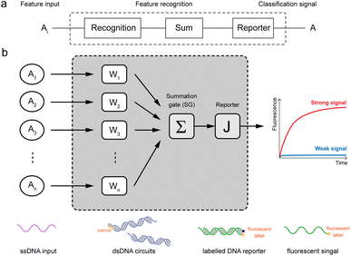 | ||
| Fig. 1 Schematic diagram of molecular recognition circuits. (a) n-input recognition logic circuit (1 ≤ i ≤ n). (b) Schematic of recognition circuits based on DNA molecules. | ||
The composition of the molecular recognition circuits is shown in Fig. 2, and mainly consists of the three steps in Fig. 2a. Reaction (I) for the recognition of inputs: different DNA inputs Ai correspond to different weight gates Wi, where the addition of fuel strands allows the sufficient reaction of the inputs. This step transformed the input Ai into the molecule Ci. This is followed by summation reaction (II) and fluorescence report (III): one or more Ci is intruded into summation gate SG, which is transformed into molecule I and then outputs the fluorescence result through the reporter gate J.
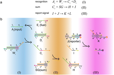 | ||
| Fig. 2 Logic design diagram of molecular recognition circuits. (a) Chemical reaction of molecular recognition circuits. (b) Molecular recognition circuits based on DNA strand displacement. | ||
The reaction process of the molecular recognition circuits based on DNA strand displacement is shown in Fig. 2b. Ai is the input whose concentration respectively represents the value, and Wi is the recognition gate, in which the sequence of domains xi is used to distinguish Ai. Domain t worked as a toehold to start strand displacement reaction. Reaction (I) consisted of a catalytic inverse reaction process that ensured the full reaction of the input Ai by adding an appropriate amount of fuel Ei, to minimize the loss of input in the cascade reaction. In reaction (II) different Ai corresponded to only one summation gate SG, and multiple inputs Ai could be summed to a result which is expressed as intermediate product I. The purpose of reaction (III) is to report the summation results. To integrate the cross-inhibition module described later, a triple-stranded complex J is designed as a reporter, in which the structural domains s* and s respectively carried the fluorophore FAM and the quencher BHQ1. When summation I is generated, it would combine with the toehold t* of the reporter and initiate branch migration, ultimately generating complex K with only the fluorophore, which outputs the fluorescence result.
Since the recognition circuit is capable of summing inputs and generating the type of signal to which it belongs, we consider the three molecular logic gates containing the recognition, sum, and reporter as a recognition module. Modules can be integrated with others in series or in a parallel way, leading to a scalability of both size and function of the molecular circuits. The circuit not only allowed the identification of target molecules to be characterized by fluorescence intensity, but also achieved a reaction process with simple and modular steps, and stable results, which made large-scale cascading possible.
2.2 Results of molecular circuit implementation
To demonstrate the feasibility of this circuit, we have analyzed both single and multi-input circuits in Fig. 3. First, a visual DSD simulation experiment was carried out to analyze the experiments for single and multiple inputs, respectively, with the Ai concentration set to 100 nM. In order to pass the input values as accurately as possible, the fuel Ei and the input Ai were at the same concentration to facilitate the reaction. Since the molecular logic gates need to be excessive for more inputs, here the concentrations of Wi and SG are set to 2![[thin space (1/6-em)]](https://www.rsc.org/images/entities/char_2009.gif) μM and the reporter to 5
μM and the reporter to 5![[thin space (1/6-em)]](https://www.rsc.org/images/entities/char_2009.gif) μM. The simulation results show that the concentrations of fluorescent molecules all increase rapidly with equally increasing inputs. 1–3 inputs produce exponentially increasing signal concentrations respectively, which shows the correct recognition and summation of input values by the recognition module. The simulated experimental results were consistent with the output as expected, which proved the accuracy of the logic.
μM. The simulation results show that the concentrations of fluorescent molecules all increase rapidly with equally increasing inputs. 1–3 inputs produce exponentially increasing signal concentrations respectively, which shows the correct recognition and summation of input values by the recognition module. The simulated experimental results were consistent with the output as expected, which proved the accuracy of the logic.
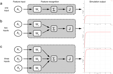 | ||
| Fig. 3 Simulation experiment results of molecular recognition circuits. (a) Simulated reaction of one-input. (b) Simulated reaction of two-inputs. (c) Simulated reaction of three-inputs. | ||
The compilation mode of this experiment was set to finite mode. The results were represented by the concentration values of the fluorescent molecules, while the y-axis represents the concentration of the fluorescent complex and the x-axis means the reaction time.
The DNA sequences used in the experiments to implement the molecular recognition circuits were all obtained via the specialized nucleic acid design and analysis software NUPACK24 (https://www.nupack.org), and manually adjusted to prevent complex instability and auto-hybridization based on the analysis results. Finally, the ssDNA sequences in the molecular recognition circuit experiment are shown in Table S1.† To fully demonstrate the thermodynamic stability of the molecular logic gates after adjusting the sequences, we analyzed the hybridization of ssDNA sequences at 37 °C (Fig. S1†).
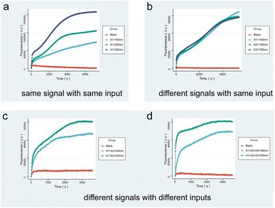
After demonstrating the robustness of the circuit and the molecular logic gates through simulation experiments, molecular experiments were performed on single input and multiple inputs to verify whether the molecular recognition circuits are regulated by concentration. In each group of experiments, excessive logic gates Wi, SG and J were added as substrates. In the quantitative curve, the x-axis represents the measuring time of the real-time quantitative PCR at a frequency of once every ten seconds of data reading, and the y-axis represents the relative intensity of the fluorescence. The reaction occurred continuously at 25 °C.
Fig. 4a indicates the fluorescence results produced by the same input A1 with different concentrations. As shown by the curve, the fluorescence intensity increases with the concentration of the input. To demonstrate that the fluorescence intensity is not affected by the sequence, Fig. 4b presents the results of different inputs A1, A2, and A3 according to the same concentration, verifying that the circuit working is not affected by the DNA sequence. Fig. 4c and 5d correspond to the results of fluorescence experiments for different concentrations of two and three different input combinations. It can be noticed that the slope of the fluorescence curve changes as the input concentration increases and the reaction proceeds faster. The fluorescence results show that for multiple inputs, the fluorescence intensity also increased with concentration of the inputs, proving that the molecular recognition circuits can be scaled according to the number of inputs.
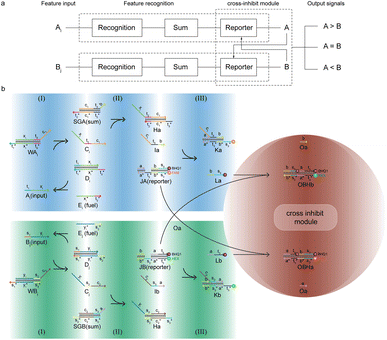 | ||
| Fig. 5 Schematic diagram of the molecular comparator design principle. (a) (n + m)-input comparator logic circuit (1 ≤ n, 1 ≤ m). (b) Molecular comparator based on DNA strand displacement. | ||
2.3 Principle of the molecular comparator
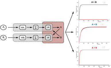
DNA logic circuits with a comparison function automatically make decisions at the molecular level. We constructed a two-input non-linear comparator by improving on the molecular recognition circuits, and the feasibility is verified by Visual DSD software simulation as well as biochemical experiments.25The design of the molecular comparator is based on a molecular recognition circuit, which is realized through the extension of the molecular recognition circuit module and the combination of cross inhibitor components (Fig. 5a). The principle is a logic circuit that recognizes and respectively sums different inputs, and compares signal A with signal B. There are three cases of results: when A is greater than B, signal A suppresses signal B, presented by the large fluorescence intensity of signal A; when A is smaller than B, signal B inhibits signal A, presented by the large fluorescence intensity of signal B; when A and B are equal, there is an equal level of inhibition between the two for the stability of the recognition circuit module, presented by the fluorescence intensity of signal A in agreement with the fluorescence intensity of signal B.
The design of the molecular comparator is based on a molecular recognition circuit, which is realized through the extension of the molecular recognition circuit module and the combination of cross inhibitor components (Fig. 5a). The principle is a logic circuit that recognizes and respectively sums different inputs, Ai and Bj, and compares signal A with signal B. There are three cases of results: when A is greater than B, signal A suppresses signal B, presented by the large fluorescence intensity of signal A; when A is smaller than B, signal B inhibits signal A, presented by the large fluorescence intensity of signal B; when A and B are equal, there is an equal level of inhibition between the two for the stability of the recognition circuit module, presented by the fluorescence intensity of signal A in agreement with the fluorescence intensity of signal B.
To distinguish different signals, the circuit involves two sets of molecular recognition circuits. When comparing two signals A and B, the inputs Ai and Bj could be recognized by WAi and WBj, and then summed by corresponding summation gates SGA and SGB. The core of the circuit, JAJB, is used to receive the summed signals A and B as well as to carry out a cross-inhibition reaction to compare the strength of them. The reaction schematic of the molecular circuit is shown in Fig. 7. In the molecular comparator, Ai and Bj are inputs about two kinds of signals, distinguished by the toehold domains t and s. The different Ai and Bj are distinguished, just like in the molecular recognition circuits, by the structural domains xi and yj, which consequently would be specifically recognized by WAi and WBj. Multiple different inputs of the same signal can be computed by summation gates, The domain c in the summation gate is used for the detection of identical signals, c1 for signal A and c2 for signal B which means that both A and B have their corresponding summation gates SGA and SGB, and the results are represented as intermediate products Ia and Ib. The molecular structures of the fluorescence reporter JA and JB consist of structural domains a, b, t and s, where a and b are particular structural domains used for cross-inhibition reactions. In the complex J, the toeholds  and
and  carried different fluorophores FAM and HEX, while s3 and t3 domains carried the quencher BHQ1. The summation resultant I migrating from SG could bind to the toehold of the reporter J, releasing a single strand and generating a complex with fluorophores to measure fluorescence intensity.
The molecular comparator is designed as a two-input molecule circuit and consists of two kinds of modules. The first module is based on the molecular recognition circuits; when an input is available, the recognition module will determine the type of input and signal, sum the similar signals, and export the fluorescence intensity. The circuit can be expanded within the recognition module to enable comparison of multiple inputs about two signals. When there is only one feature input, the summation gate merely functions as a signal transform. The second type of module of the molecular comparator performs the comparison operation based on the principle of cross-inhibition. Such a design simplified the process of comparing the signals individually, rather than annihilating each other two by two, but directly judges their fluorescence intensities to determine the result. The cross-inhibition reaction caused Ia and Ib to invade the reporters of each other's signals, resulting in the suppression of each other's fluorescent signal reports without introducing other molecules. As the two reporters were modified with different fluorophores, the results were directly determined by the fluorescence intensity and were clear and easy to read.
2.4 Results of the molecular comparator implementation
To verify the logical accuracy of the molecular comparator, we performed a Visual DSD simulation experiment to further demonstrate its feasibility by simulating three cases of the two-input experiment. Three groups of experiments were input with different concentrations of A and B signals, and the results of the simulation experiments are shown in Fig. 6, from top to bottom, as >B, A = B, and A < B. It can be observed that the molecular comparator could compare two signals of different concentrations, and the results are consistent as expected: when the concentrations of the two signals were unequal, only the fluorescence curve of the signal of the high concentration was output; when the concentrations of the two signals were equal, the fluorescence curves of the two signals were output at the same time. The results confirmed the logical accuracy and feasibility of the molecular comparator.After determining that the design of the molecular comparator was feasible, we tested the performance of the molecular comparator through fluorescence experiments, specifically by adjusting the concentration of two inputs to validate the 2-input molecular comparator which was designed based on the molecular recognition circuits. The signal magnitude is represented by the input concentration and the final result is visually compared by the fluorescence intensity. The DNA sequences used in the experiment are shown in Table S2.† Fig. S2† displays the MFE structure of the DNA logic gates involved in the 2-input molecular comparator experiment, and the low free energy of the secondary structures indicated that they were as stable as in the recognition circuits.
Real-time fluorescence quantification experiments were performed using the above logic gate molecules and the results are shown in Fig. 7. Signal A is finally output by the FAM-modified fluorescence reporter JA, and signal B is finally output by the HEX-modified fluorescence reporter JB. OA is the real-time fluorescence curve of signal A, and OB is the curve of signal B. OA-blank and OB-blank are blank groups. All molecules other than the input strand were added to the blank group. Fig. 7a shows that that FAM fluorescence was stronger than HEX when signal A > B, while Fig. 7b demonstrates that FAM and HEX fluorescence intensities were almost equal after t = 2500 s when signal A = B, and we considered that JA and JB inhibit each other to a comparable extent. Fig. 7c exhibits that FAM fluorescence is weaker than HEX when signal A < B. The experimental results for all three cases indicated that the signal outputs conformed to the design expectations of the molecular comparator.
 | ||
| Fig. 7 Real-time fluorescence curve of the molecular comparator. (a) The result of signal A > B. (b) The result of signal A = B. (c) The result of signal A < B. | ||
3 Conclusion
In this paper, we developed a molecular circuit capable of recognizing and summing inputs that contain stable complexes for fluorescence reporting. After proposing the molecular model, we have validated it from simulated strand displacement reaction experiments and molecular experiments in the tube, including analyses of the molecular circuits' logical accuracy, robustness, and scalability. The results showed that the molecular circuit can recognize and sum the output of single or multiple signals of the same or different concentrations in the experiment. After achieving success of molecular recognition circuits, we constructed a molecular comparator by novelly introducing a cross-inhibition module between two recognition circuit modules through sequence correlation of DNA logic gates. This allowed us to decide how many different inputs we need within the same recognition module by defining the xi and yj domains, and how many different recognition modules were needed in total by defining the sequence of toehold domains. The recognition modules are used internally to identify the corresponding inputs and externally to compare different signals, which reflected the scalability of the initial design of this molecular recognition circuit. In the same way, we verified that a 2-input comparator can automatically determine 3 different cases in both simulation and molecular experiments. The implementation of the molecular comparator not only confirmed that the designed molecular recognition circuits can be cascaded to achieve more complex logic circuit functionality, but also demonstrated its potential for application in bio-computing.The modular molecular recognition circuits we designed could be used as processing devices for multiple inputs, such as the classification of multiple pattern inputs in intelligent DNA circuits. The molecular comparator is a DNA circuit that can automatically make a judgement on the magnitude of multiple signals, which can be applied to DNA computing models in several situations or provide insights into quantitative analysis tasks in biosensors. Due to the enzyme-free character of the entire system, the experimental environment and consumables are low-cost, and the reaction process is stable. Moreover, the higher level of modularity enabled easy expansion of the circuit: three logic gate molecules were required for the first input within each recognition module; only one logic gate and one fuel strand were added for each additional input above the initial foundation. Furthermore, the adoption of a cross-inhibition module is only related to the sequence of the reporter and no other logic gates need to be attached. Therefore, adding logic gates within the recognition module or increasing the number of modules as the scope of the circuit grows could extend more complex bio-computing functions. The circuit has been tested in both simulations and molecular experiments, which provided new ideas for DNA computing models, and enriched the toolbox of intelligent DNA circuits or DNA sensors as a fast and concise way to take in and process multiple signals.
Data availability
The data that support the findings of this study are available from the corresponding authors, upon reasonable request.Author contributions
Fang Wang: conceptualization, methodology, writing – original draft. Beiyu Shi: data curation, writing – original draft. Ying Chen: validation, writing – review & editing. Xiaolong Shi: writing – review & editing. Zheng Kou: funding acquisition, writing – review & editing. Xiaoli Qiang: formal analysis, funding acquisition, writing – review & editing.Conflicts of interest
The authors declare that they have no known competing financial interests or personal relationships that could have appeared to influence the work reported in this paper.Acknowledgements
This work was supported by the National Key R&D Program of China (2019YFA0706402), the National Natural Science Foundation of China (62172114, 61972109, 62072129, and 62332006), the Natural Science Foundation of Guangdong Province of China (2022A1515011468) and the Funding by Science and Technology Projects in Guangzhou (202201020237, 202201020179, and SL2022A03J01035).Notes and references
- L. M. Adleman, science, 1994, 266, 1021–1024 CrossRef CAS PubMed.
- R. S. Braich, N. Chelyapov, C. Johnson, P. W. Rothemund and L. Adleman, Science, 2002, 296, 499–502 CrossRef CAS PubMed.
- T. Chen and M. Riedel, ICASSP 2020-2020 IEEE International Conference on Acoustics, Speech and Signal Processing, ICASSP, 2020, pp. 8836–8840 Search PubMed.
- C. Chen, J. Xu, L. Ruan, H. Zhao, X. Li and X. Shi, Nanoscale, 2022, 14, 5340–5346 RSC.
- J. Xu, IEEE Transact. Neural Networks Learn. Syst., 2016, 27, 1405–1416 Search PubMed.
- H. Eghdami and M. Darehmiraki, Artif. Intell. Rev., 2012, 38, 223–235 CrossRef.
- D. Y. Zhang and E. Winfree, J. Am. Chem. Soc., 2009, 131, 17303–17314 CrossRef CAS PubMed.
- J. Xu, X. Qiang, K. Zhang, C. Zhang and J. Yang, Engineering, 2018, 4, 61–77 CrossRef CAS.
- G. Seelig, D. Soloveichik, D. Y. Zhang and E. Winfree, Science, 2006, 314, 1585–1588 CrossRef CAS PubMed.
- A. P. Lapteva, N. Sarraf and L. Qian, J. Am. Chem. Soc., 2022, 144, 12443–12449 CrossRef CAS PubMed.
- X. Chen, X. Liu, F. Wang, S. Li, C. Chen, X. Qiang and X. Shi, ACS Synth. Biol., 2022, 11, 2504–2512 CrossRef CAS PubMed.
- M. Qi, P. Shi, X. Zhang, S. Cui, Y. Liu, S. Zhou and Q. Zhang, RSC Adv., 2023, 13, 9864–9870 RSC.
- H. Geng, Z. Yin, C. Zhou and C. Guo, Acta Biomater., 2020, 118, 44–53 CrossRef CAS PubMed.
- C. Liu, Y. Liu, E. Zhu, Q. Zhang, X. Wei and B. Wang, Nucleic Acids Res., 2020, 48, 10691–10701 CrossRef CAS PubMed.
- J. Fern, D. Scalise, A. Cangialosi, D. Howie, L. Potters and R. Schulman, ACS Synth. Biol., 2017, 6, 190–193 CrossRef CAS PubMed.
- S. X. Chen and G. Seelig, International Conference on DNA-Based Computers, 2017, pp. 110–121 Search PubMed.
- B. Dou, J. Yang, K. Shi, R. Yuan and Y. Xiang, Biosens. Bioelectron., 2016, 83, 156–161 CrossRef CAS PubMed.
- L. Qian and E. Winfree, Science, 2011, 332, 1196–1201 CrossRef CAS PubMed.
- A. Eshra, S. Shah, T. Song and J. Reif, IEEE Trans. Nanotechnol., 2019, 18, 252–259 CAS.
- N. V. DelRosso, S. Hews, L. Spector and N. D. Derr, Angew. Chem., Int. Ed., 2017, 56, 4443–4446 CrossRef CAS PubMed.
- G. Joya, M. Atencia and F. Sandoval, Neurocomputing, 2002, 43, 219–237 CrossRef.
- L. Qian, E. Winfree and J. Bruck, Nature, 2011, 475, 368–372 CrossRef CAS PubMed.
- K. M. Cherry and L. Qian, Nature, 2018, 559, 370–376 CrossRef CAS PubMed.
- J. N. Zadeh, C. D. Steenberg, J. S. Bois, B. R. Wolfe, M. B. Pierce, A. R. Khan, R. M. Dirks and N. A. Pierce, J. Comput. Chem., 2011, 32, 170–173 CrossRef CAS PubMed.
- M. R. Lakin, S. Youssef, F. Polo, S. Emmott and A. Phillips, Bioinformatics, 2011, 27, 3211–3213 CrossRef CAS PubMed.
Footnote |
| † Electronic supplementary information (ESI) available. See DOI: https://doi.org/10.1039/d4na00379a |
| This journal is © The Royal Society of Chemistry 2024 |

