 Open Access Article
Layered MOF supported on 2D delaminated MXene (Mo2Ti2C3) nanosheets boosted water splitting†
Maida
Murtaza
a,
Komal
Farooq
a,
Waqas Ali
Shah
ab,
Iftikhar
Ahmad
a and
Amir
Waseem
 *a
*a
aDepartment of Chemistry, Quaid-i-Azam University, Islamabad, Pakistan. E-mail: amir@qau.edu.pk
bSchool of Chemistry and Chemical Engineering, Henan Normal University, Xinxiang, 453007, China
First published on 21st October 2024
Abstract
Metal organic frameworks (MOFs) have a porous structure, high surface area, and high charge transfer, and they have been regarded as model electrocatalysts. Optimization of the electrocatalytic activity of MOFs is challenging, and an effective strategy for this optimization is the construction of a well-defined interfacial bond bridge. In this work, an in situ approach of composite synthesis is reported for MOF (CoNiNH2BDC) with MXenes (Mo2Ti2C3), as the electrocatalytic properties of MOF can be greatly enhanced with the incorporation of the conductive material MXene. The prepared composite material was characterized thoroughly using XRD, XPS, FESEM, EDX, TEM, and BET. The synergistic effect of both components of this composite material resulted in enhanced conductivity and the number of active sites, which led to enhanced electrocatalytic performance. The CoNiNH2BDC MOF with different ratios of Mo2Ti2C3 MXene were synthesized, and the resulting materials were evaluated for oxygen evolution reaction (OER) and hydrogen evolution reaction (HER) activities. It was observed that the MOFMX3 attained a 10 mA cm−2 current density at 1.44 V for OER and −0.037 V for HER (vs. RHE), and lower values of Tafel slopes of 44.8 mV dec−1 for OER and 45 mV dec−1 for HER in 0.1 M KOH were achieved. The higher double layer capacitance (Cdl) values lead to high electrochemical surface area (ECSA) values. Lower Tafel slope values for MOFMX3 show that the presence of MXene nanosheets in the hybrid provides support to the layered and porous configuration of MOF, and the chances of the interaction of electrolyte to the catalytically active sites are significantly enhanced. This work highlights the idea of growing bimetallic MOFs on Mo2Ti2C3 MXene using an interdiffusion reaction strategy and opens up an avenue for designing highly electrocatalytic systems.
1. Introduction
Sustainable energy production is a goal around the globe, and as the population of the world increases, energy demands increase. Therefore, it is crucial to find energy sources that are environmentally friendly, sustainable and less hazardous to life on this planet.1,2 Hydrogen is one of the most used energy sources, and hydrogen is mostly produced from the combustion of coal, which is harmful as it is the cause of global warming and increased carbon dioxide levels in the environment. Therefore, a safe source of hydrogen production is required that can suppress CO2 emissions in the environment and make life on Earth more sustainable. Water splitting is one of the sustainable sources for the production of green hydrogen. Water splitting comprises water oxidation, i.e. oxygen evolution reaction (OER), occurring at the anode, and water reduction reaction, i.e. hydrogen evolution reaction (HER), occurring at the cathode.3 To achieve better efficiency of these OER and HER reactions, we need electrocatalysts that are economical, abundant, and non-toxic and those can compensate for the sluggish reaction kinetics and provide results with lower overpotential values. An emerging class of compounds comprising inorganic metal and an organic ligand (also known as linker) is metal organic frameworks (MOFs) that possess high porosity, tunable structure, and high flexibility.4–6 In the structure of MOFs, metal units are uniformly dispersed in the network; therefore, MOFs behave as efficient homogeneous and heterogeneous catalysts.7–9 MOFs have been reported as electrocatalysts, but MOFs have poor conductivity, and it is required to develop MOF composites with conductive materials for enhancing the conductivity of MOFs; to date, a limited number of such MOF composites have been reported for their applications in electrocatalysis, and there is a room of research available to design and develop MOF composites for better efficient OER and HER catalysts.10,11A class of 2D materials known as MXene is a highly conductive material synthesized from the MAX phase, commonly known for layered materials with a common formula Mn+1AXn (n = 1, 2, 3), where M represents metals (such as M = Ti, V, and Mo), A is usually aluminum/gallium and X denotes N/C. Some basic properties that MXenes offer are high conductivity, corrosion resistance, layered structure, and faster charge transfer mechanism12–14 and can be modified in various ways to achieve desired properties15 and MOF composites with conductive substrates, such as rGO and CNTs, have also been reported.16 The combination of MXenes with MOFs can result in a better catalyst/electrocatalyst, but this combination is rarely reported.15,17 With all of the above-mentioned discussion, we designed MOF@MXene hybrids as electrocatalysts for OER and HER activities. A 2D MOF was synthesized using an aminoterephthalic acid linker with cobalt and nickel, which was further decorated on Mo2Ti2C3 MXene sheets by applying an interdiffusion reaction strategy. Detailed characterizations, such as XRD, FESEM, EDX, TEM, XPS, and BET, were carried out to confirm the composite synthesis. In view of the tunability in the structure of MOFs and their chemical diversity, the approach shown in this work, i.e., in situ hybridization, is most favorable for the synthesis of MOF MXene hybrids for the synthesis of electrocatalysts for green hydrogen production.
2. Materials and methods
2.1 Materials
Molybdenum titanium aluminum carbide was purchased from Chemazone Inc., Nanochemazone™ (Canada). N,N-Dimethylformamide (DMF), potassium hydroxide (KOH), nickel nitrate hexahydrate (Ni(NO3)2·6H2O), and hydrogen fluoride (HF) were purchased from ISOLAB. Aminoterephthalic acid (NH2BDC), cobalt nitrate hexahydrate (Co(NO3)2·6(H2O)), and glassy carbon electrode were bought from Sigma-Aldrich. All the chemicals were used without further purification.2.2 Synthesis of Mo2Ti2C3Tx
From the MAX phase (Mo2Ti2AlC3), the ‘A’ layer was removed for the synthesis of Mo2Ti2C3 MXene by etching with HF. In 30 ml of HF, 2 g of Mo2Ti2AlC3 was added slowly, and the solution was kept at magnetic stirring for 24 hours at 40 °C. Centrifugation and washing of the solution were done at 8000 rpm with distilled water until the pH reached 7 (neutral). The material was dried overnight at 70 °C.2.3 Synthesis of CoNH2BDC, NiNH2BDC, and CoNiNH2BDC MOF
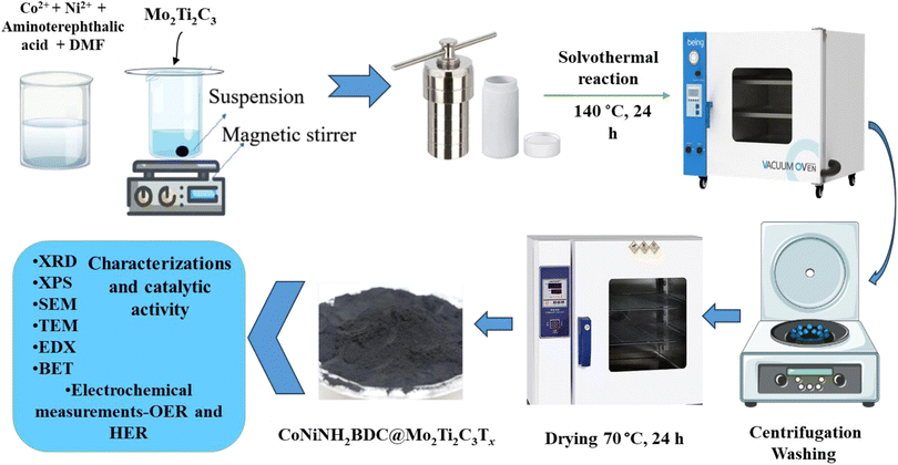
CoNiNH2BDC was synthesized by the reported solvothermal process with slight amendments.18 Concisely, 0.8 g of aminoterephthalic acid (NH2BDC), 0.6 g of each nickel and cobalt salt were added into 40 ml of DMF and to homogenize this mixture, and it was kept at magnetic stirring for an hour. The homogenized mixture was then kept in the oven at a temperature of 140 °C for 24 hours after transferring into a Teflon-lined autoclave. After heating for 24 hours, the autoclaves were kept closed until they cooled at room temperature; then, the washing of the synthesized material was done with DMF and ethanol by centrifugation at 5000 rpm (three times), and the material was dried overnight at 70 °C.CoNH2BDC was synthesized using the same above-mentioned solvothermal method. A mixture of 0.6 g of Co(NO3)2·6H2O, 0.4 g of NH2BDC, and 40 ml of DMF was kept at magnetic stirring for an hour, then poured into the Teflon-lined autoclave and kept in the oven at 140 °C for 24 hours. Centrifugation, washing, and drying of the prepared material were performed under the same conditions mentioned above for the synthesis of CoNiNH2BDC.
Synthesis of NiNH2BDC was done using a method similar to CoNH2BDC (0.6 g of Ni(NO3)2·6H2O), and 0.4 g of NH2BDC was added to DMF (40 ml). The solvothermal reaction was carried out under similar temperature and time conditions, and similar conditions for centrifugation, washing, and drying.
2.4 Synthesis of CoNiNH2BDC MOF@Mo2Ti2C3Tx
CoNiNH2BDC@MXene hybrid was prepared analogous to that of the CoNiNH2BDC except for the addition of a definite quantity of etched MXene along with 0.6 g of Ni(NO3)2·6H2O, 0.6 g Co(NO3)2·6H2O, 0.8 g of NH2BDC, and 40 ml of DMF. The mixture was kept at magnetic stirring for one hour for homogenization. The homogenized mixture was then transferred into a Teflon-lined autoclave and kept in the oven at a temperature of 140 °C for 24 hours. After heating for 24 hours, the autoclaves remained closed until they cooled at room temperature; then, the washing of the synthesized material was done by centrifugation at 500 rpm (three times) with DMF and ethanol subsequently, and the material was dried overnight at 70 °C. Preparation of CoNiNH2BDC@Mo2Ti2C3Tx hybrids was prepared as described above; however, during MOF synthesis, different concentrations of Mo2Ti2C3Tx (5, 10, and 15 wt%) were added to the solution, and these prepared hybrids were named MOFMX1, MOFMX2 and MOFMX3, respectively, as described in Scheme 1.2.5 Characterizations
X-ray diffraction analysis was performed using the “Bruker D2 Phaser” instrument with CuKα radiation (λ = 1.54 Å) source. Field emission scanning electron microscopy analyses were performed using a “Zeiss Ultra Plus” instrument equipped with EDX spectroscopy. The specific surface area of the synthesized material was calculated using “Quantachrome instruments NOVA Touch”. For XPS measurements, a “Thermo K-alpha” system was used with a monochromatized AlKα X-ray source. A “JEOL JEM-2100F” field-emission transmission electron microscope was used to obtain the TEM images.2.6 Electrochemical study
Using the Zahner Potentiostat with a three-electrode cell design, the electrocatalytic activity of the prepared catalysts was measured, and a 0.1 M KOH solution was used as an electrolyte. Catalyst-loaded glassy carbon electrode was used as the working electrode, and platinum wire and Ag/AgCl were used as counter and reference electrodes, respectively. The Nernst equation was used for converting potential to versus reversible hydrogen electrode (RHE):19,20| ERHE = EAg/AgCl + 0.059 pH + E0Ag/AgCl, |
3. Results and discussion
3.1. Characterizations
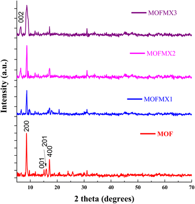
The powder X-ray diffraction (XRD) pattern of the Max phase (Mo2Ti2AlC3) (Fig. S1†) shows clear and distinct peaks. The Max phase (Mo2Ti2AlC3) shows the diffraction peaks of interest at the 2θ values of 8.9° (002), 19.1° (004), and 28.5° (006). After etching the Max phase with HF, these diffraction peaks shifted to lower 2θ values of 6.58°, 12.65°, and 24.2° for plane indices of (002), (004), and (006), respectively, as reported previously.22,23 The increase in the d-spacing ascribed to the intercalation of water molecules and surface termination groups (Mo2Ti2C3Tx MXene), e.g. Tx = –O, –OH, and –F, after the removal of the “Al” layer.24 The appearance of a prominent peak at the (002) plane of Mo2Ti2C3 MXene, which is more intense than the pristine Max phase, suggests structural stability and crystallinity (Fig. S1†) after delamination. The peaks between the 2θ values of 33°–45° and 50–70° almost disappeared after successful “Al” etching from the Mo2Ti2AlC3 Max phase. The successful synthesis of MOFMX composites is shown in Fig. 1. The important signals appear at 2θ values of 8.6°, 14.6°, 15.1°, 16.1°, and 17.2° and can be assigned to (200), (00![[1 with combining macron]](https://www.rsc.org/images/entities/char_0031_0304.gif) ), (20
), (20![[1 with combining macron]](https://www.rsc.org/images/entities/char_0031_0304.gif) ), and (400) planes, respectively, of a layered triclinic structure. Similarly, the other signals are in the range of 2θ values of 25°–35°. In addition, Fig. S2† shows the XRD signals of CoNH2BDC MOF and NiNH2BDC MOF, and the overall XRD pattern of CoNiNH2BDC MOF agrees well with the XRD standard card of Ni-MOF (CCDC No. 985792), as previously reported.18,25In situ growth of MOF on the surface of layers of MXene was confirmed by the XRD pattern of the composite. The presence of a small signal at a 2θ value of 6.6° indicates that the MXene is incorporated successfully during the MOFMX composite formation, which is in line with the previously reported study.26 The other XRD signal of the composite is similar to pristine MOF. However, a decrease in intensity and peak broadening was observed.27
), and (400) planes, respectively, of a layered triclinic structure. Similarly, the other signals are in the range of 2θ values of 25°–35°. In addition, Fig. S2† shows the XRD signals of CoNH2BDC MOF and NiNH2BDC MOF, and the overall XRD pattern of CoNiNH2BDC MOF agrees well with the XRD standard card of Ni-MOF (CCDC No. 985792), as previously reported.18,25In situ growth of MOF on the surface of layers of MXene was confirmed by the XRD pattern of the composite. The presence of a small signal at a 2θ value of 6.6° indicates that the MXene is incorporated successfully during the MOFMX composite formation, which is in line with the previously reported study.26 The other XRD signal of the composite is similar to pristine MOF. However, a decrease in intensity and peak broadening was observed.27
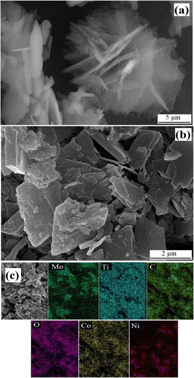
The morphological aspects of the pristine Max phase, MXene, MOF and MOFMX composites were analyzed through field emission scanning electron micrographs (FESEM). Fig. S3a and b† show the pristine Max phase of Mo2Ti2AlC3 2D-layered material with large solid lumps. However, after etching “Al” with HF, prominent stacked 2D layered MXene (Mo2Ti2C3) can be observed, as shown in Fig. S2b.† After etching and delamination, separated layers of the MXene are clearly observed in Fig. S3d.† (refs. 8 and 28) Fig. 2 shows the flower-like morphology of the pristine CoNiNH2BDC MOF with 2D flaked petals, similar to the previously reported layered 2D flake-like morphology.26,29 CoNiNH2BDC MOF was grown on the surface of the layers of Mo2Ti2C3 MXene. Fig. 2b clearly shows the growth of flaked CoNiNH2BDC MOF on the surface of delaminated 2D layers of MXene, which is also confirmed through the elemental mapping of the composite (Fig. 2c).
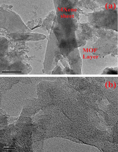
TEM analysis was also performed for MOFMX3 composites, and the images are depicted in Fig. 3, which shows a plate-like arrangement of MOF (light colored) on the surface of MXene.
The XPS survey scan of Mo2Ti2C3 MXene, CoNiNH2BDC MOF, and MOFMX composites is shown in Fig. S4.† XPS survey scan of Mo2Ti2C3 MXene shows the presence of Mo, Ti, C, O, and F, and the absence of Al confirms successful etching during MXene formation. The survey scan CoNiNH2BDC MOF shows the presence of Co, Ni, C, N, and O elements. The XPS of the MOFMX composite confirms the presence of all its elements from MOF and MXene, i.e., Co, Ni, Mo, Ti, C, and O.
As shown in Fig. 4a, the high-resolution XPS spectra of Mo 3d in the MOFMX composite deconvoluted into three fitting crests at 228.8 eV, 232 eV and 235.3 eV, agreeing well with Mo–C (3d5/2), Mo–C (3d3/2), and Mo–Ox (3d3/2) bonds, respectively.13,23 Similarly, Fig. 4a (lower) shows the fine XPS spectra of Mo 3d of Mo2Ti2C3 MXene where all the bands match well with the previously reported studies.22,24 The XPS spectrum of Ti 2p (Fig. 4b) shows the binding energies at 454.8 eV and 460.6 eV, the doublet allocated to Ti 2p3/2 and 2p1/2, respectively, which signifies Ti–C species, which agrees with the reported work.30 Signals at 458.3 eV and 463.8 eV binding energies, respectively, demonstrate the oxidation states of Ti species (Ti–Ox, Ox = O, OH, F), as reported previously.31 Similarly, within the Ti 2p spectrum Ti–Al entities were not present in both the XPS spectra of MOFMX composite and Mo2Ti2C3 MXene, which indicates that Al was absent and MXene was etched properly; the Al layer was successfully removed by hydrofluoric acid (Fig. 4b lower). The presence of Mo 3d and Ti 2p in the MOFMX composite sample confirms the incorporation of MXene into the composite formation. The high-resolution spectra of Co 2p and Ni 2p of the MOFMX composite show the bands at binding energies of 780.8 eV (2p3/2) and 796.4 eV (2p1/2), and 855.1 eV (2p3/2) and 872.4 (2p1/2) eV, respectively, which are similar to the previously reported studies25 (Fig. 4c and d). Additionally, two broad satellite peaks are observed in both of the cases Co 2p and Ni 2p at 784.8 eV and 801.6 eV, and 860.2 eV and 878.9 eV binding energies, respectively.27,32 The carbon spectrum exhibits major bands (C 1s) at 284.77 eV, 285.9 eV, and 288.7 eV binding energies for the C–C bond, C–O and C![[double bond, length as m-dash]](https://www.rsc.org/images/entities/char_e001.gif) O species (Fig. S5†), respectively. Another broad peak at the binding energy of 282.4 eV was also observed, which confirms the presence of the C–M bond, similar to the C–M bond in Mo2Ti2C3 MXene; however, this band is not observed in CoNiMOF, which suggests successful MOFMX composite formation (Fig. S5†). The XPS spectrum of O 1s shows the major deconvoluted peaks at binding energies of 531.2 eV and 532.6 eV and can be ascribed to O
O species (Fig. S5†), respectively. Another broad peak at the binding energy of 282.4 eV was also observed, which confirms the presence of the C–M bond, similar to the C–M bond in Mo2Ti2C3 MXene; however, this band is not observed in CoNiMOF, which suggests successful MOFMX composite formation (Fig. S5†). The XPS spectrum of O 1s shows the major deconvoluted peaks at binding energies of 531.2 eV and 532.6 eV and can be ascribed to O![[double bond, length as m-dash]](https://www.rsc.org/images/entities/char_e001.gif) C and O–C, respectively (Fig. S6†). The signal at the binding energy of 529.9 eV shows the existence of an O–M bond (M = Mo, Ti, Co, Ni), this signal is very prominent in the case of Mo2Ti2C3 MXene (Fig. S6†). The presence of this signal further confirms the successful incorporation of MXene in the MOFMX composite, and it is backed by the reported studies.26,31,33
C and O–C, respectively (Fig. S6†). The signal at the binding energy of 529.9 eV shows the existence of an O–M bond (M = Mo, Ti, Co, Ni), this signal is very prominent in the case of Mo2Ti2C3 MXene (Fig. S6†). The presence of this signal further confirms the successful incorporation of MXene in the MOFMX composite, and it is backed by the reported studies.26,31,33
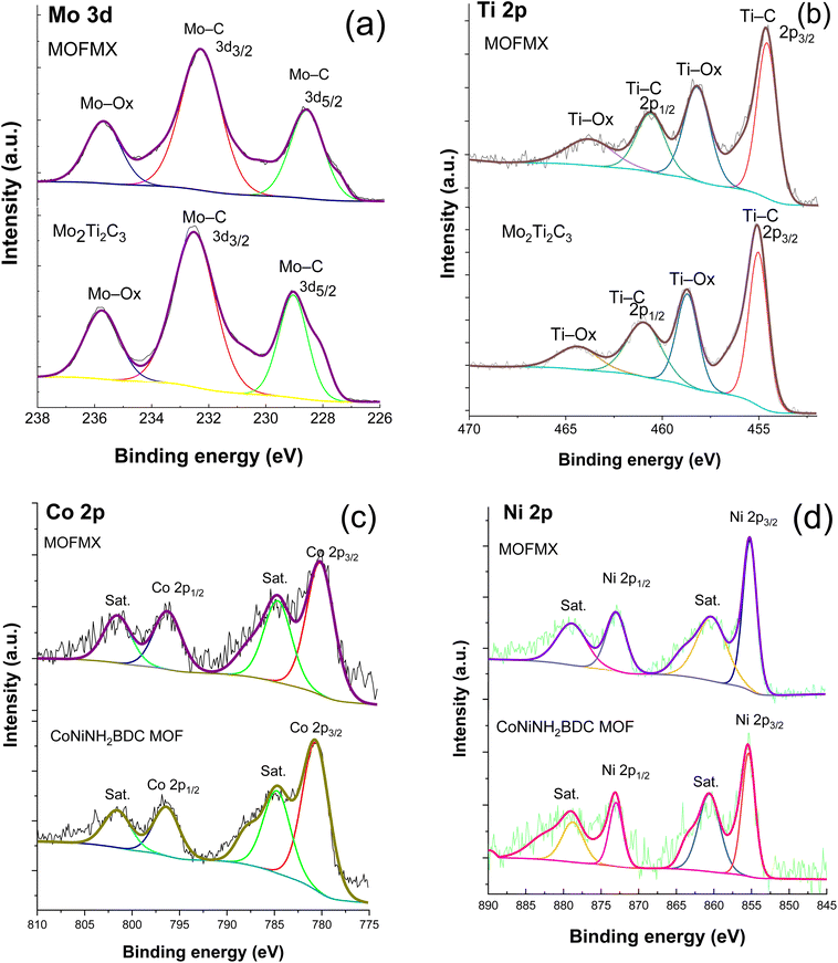 | ||
| Fig. 4 High-resolution XPS of Mo 3d (a), Ti 2p (b), Co 2p (c), Ni 2p (d) of CoNiNH2BDC, Mo2Ti2C3 and MOFMX composite compared with each other. | ||
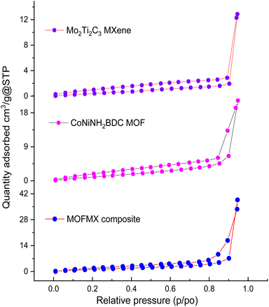
To inquire about the specific surface area (SBET) and porosity of Mo2Ti2C3 MXene, CoNiNH2BDC MOF and MOFMX composite, nitrogen adsorption–desorption analysis was performed. The isotherm shape shows a type-IV curve with an H3 distinct hysteresis loop, which implies the existence of mesoporous pores.29 Mo2Ti2C3 MXene and CoNiNH2BDC MOF show the typical isotherm for layered structures with SBET of 3.0 m2 g−1 and 11.2 m2 g−1, respectively. The enhanced surface area of the MOFMX composite was observed with the MXene addition and recorded as 14.6 m2 g−1 (Fig. 5), as in previously reported studies.23,34 The increased surface area shows the growth and alignment of 2D MOF sheets with MXene nanosheets for the creation of void spaces of various sizes. The mesoporous structure of the MOFMX composite with a higher surface area is supposed to be accountable for improved electrocatalytic efficiency than pristine MOF, as discussed later in this work.
3.2. Electrocatalytic performance
The electrocatalytic efficiency of NiNH2BDC, CoNH2BDC, and CoNiNH2BDC was tested for both OER and HER using a three-electrode system in 0.1 M KOH solution (electrolyte). The electrocatalytic OER efficiency of the above-mentioned catalysts is shown by linear sweep voltammetry (LSV) (Fig. 6). From Fig. 6, we can conclude that bimetallic CoNiNH2BDC MOF showed enhanced OER activity compared to the pristine CoNH2BDC and NiNH2BDC MOFs, as it showed early onset potential and attained a current density of 10 mA cm−2 at 1.496 V vs. RHE. Equal loading of the catalyst on the conductive substrate was done, i.e., 0.2 mg cm−2. Mo2Ti2C3 composites of CoNiNH2BDC, MOFMX1, MOFMX2, and MOFMX3 were evaluated to measure the OER activity by LSV (Fig. 6a). MOFMX3 showed remarkable results with an early onset and obtained a 10 mA cm−2 current density at 1.443 V vs. RHE, while MOFMX1, MOFMX2, and MOFMX4 attained current densities of 10 mA cm−2 at 1.487 V, 1.453 V, and 1.451 V vs. RHE, respectively (Fig. 6 and S7†). MOFMX3 exhibits an exceptionally low overpotential of 215 mV, indicating efficient OER activity. MOFMX1 and MOFMX2 showed enhanced OER activity with overpotentials of 257 mV and 223 mV at 10 mA cm−2, respectively, compared to CoNiNH2BDC with an overpotential value of 266 mV. As MXene is a conductive material, its layered structure increased the catalytic sites on the surface and hence enhanced OER performance from these hybrid materials; however, increasing the MXene concentration up to 15% (MOFMX3) is sufficient to have excellent OER activity (Fig S7†). Tafel slope values are shown in Fig. 6b, and MOFMX3 showed the lowest Tafel slope value of 44.8 mV dec−1, while MOFMX1 showed 77 mV dec−1, and MOFMX2 showed 57 mV dec−1. However, CoNiNH2BDC possesses a higher Tafel slope value of 89 mV dec−1 among these catalysts. The lowest value of the Tafel slope for MOFMX3 indicates higher reaction kinetics. The remarkably good electrocatalytic OER performance of the CoNiNH2BDC MOF hybrid with Mo2Ti2C3Tx shows the synergistic effect of both components of this hybrid material. CoNiNH2BDC MOF has a porous structure and a large surface area and has shown good OER catalytic activity. A combination of Mo2Ti2C3Tx with CoNiNH2BDC MOF further increased the surface area, as shown in Fig. 5. Structural support is provided by MXene nanosheets to the MOF structure and enhances the exposed surface area; hence, the number of active sites increases, and MXene also helps in preventing the aggregation of layers and, therefore, enhanced surface area, which ultimately results in enhanced catalytic activity. Double layer capacitance (Cdl) at the liquid interface was measured by taking cyclic voltammetry (CV) at different scan rates of 50, 100, 150, 200, 250, and 300 mV s−1 in the non-faradaic region; janodic–jcathodic/2 was plotted against scan rates, and Cdl was calculated from it. MOFMX3 showed the highest value of Cdl 9.42 mF cm−2 compared to the bare MXene (1.13 mF cm−2), CoNiNH2BDC MOF (1.17 mF cm−2), MOFMX1 (2.31 mF cm−2), and MOFMX2 (7.52 mF cm−2) (Fig. S8†). This clearly indicated that this hybrid did not only support the porous structure but also that there was easy access of the electrolyte to the catalytic active sites. Electrochemical impedance spectroscopy (EIS) measurement was done in the frequency ranging from 1 Hz to 1 kHz, and the Nyquist plot (Fig. S9†) of MXene and MOF showed higher charger transfer resistance in comparison to the MOFMX3 that showed the smallest semi-circle, indicating lowest charge transfer resistance, which is again confirmation of intrinsically high surface area, enhanced conductivity, and easy transfer of charges at the electrode–electrolyte interface. The stability of the catalyst was examined by continuous 1000 CVs at 5 mV s−1, and it was observed that the initial and after CV cycles were majorly similar, indicating that this material was highly stable (Fig. 6c) .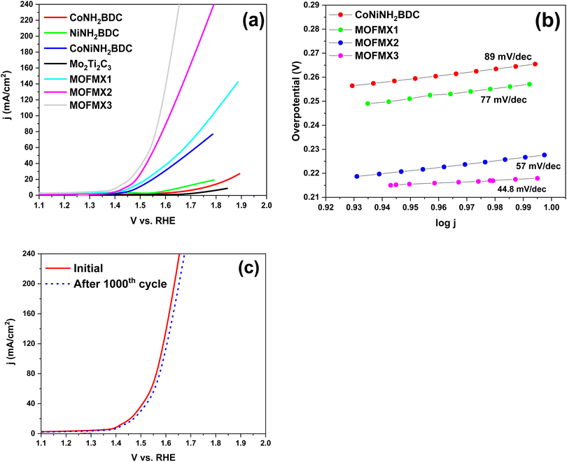 | ||
| Fig. 6 Electrocatalytic OER efficiency (a) LSV curves, (b) Tafel slope, (c) LSV curves of MOFMX3 before and after 1000 CV cycles. | ||
The LSV curves of the as-prepared catalyst for HER activities are shown in Fig. 7a. It is evident from these LSVs that bimetallic CoNiNH2BDC showed the best HER results among the above-mentioned catalysts, even though they were lower than those of MOFMX3. LSV curves of MOFMX1, MOFMX2, MOFMX3 and MOFMX4 composites are shown in Fig. S10.† It is evident that the HER activity shows an increasing trend by increasing MXene concentration in MOFMX composite and is maximum with MOFMX3, which is because the addition of MXene can facilitate electron transfer. However, beyond the optimum concentration of MXene, further addition can also block the catalytic active sites of the catalyst, thereby reducing the catalytic performance. Among the catalysts, MOFMX1, MOFMX2, and MOFMX3 achieved a current density of 10 mA cm−2 at 123 mV, 93 mV, and 37 mV, respectively, for HER, while Mo2Ti2C3Tx and CoNiNH2BDC MOF attained a current density of 10 mA cm−2 at 224 mV and 135 mV, respectively. MOFMX3 showed the earliest onset and lower overpotential value among these catalysts and hence the best HER performance among these. The Tafel slope value of MOFMX3 is smaller, and it indicates faster reaction kinetics of the catalyst towards HER (Fig. 7b). This could be possibly due to the formation of hydronium ions on the surface of the catalyst in 0.1 M KOH alkaline solution (electrolyte) and hence better catalytic activity and faster reaction kinetics as well. To inquire about the catalyst stability, continuous 1000 CVs were analyzed, and no significant difference in the initial LSV and after CV cycles LSV was observed, indicating that this material is highly stable (Fig. 7c).
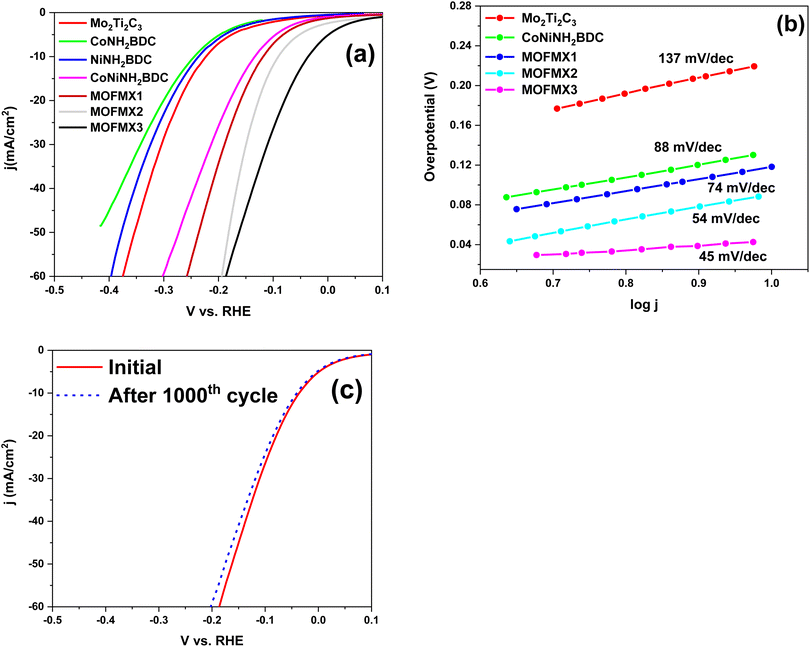 | ||
| Fig. 7 Electrocatalytic HER efficiency (a) LSV curves, (b) Tafel slope, and (c) LSV curves of MOFMX3 before and after 1000 CV cycles. | ||
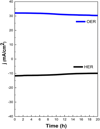
Chronoamperometry measurement was also performed to examine the stability of the catalyst and was carried out at 1.48 V vs. RHE for OER and −0.04 vs. RHE for HER for 20 hours. Strong durability in a prolonged chronoamperometry test was shown by MOFMX3, and it exhibited slight degradation, demonstrating its high durability (Fig. 8). With uninterrupted measurements, 97% of the initial current density was retained for up to three hours, and 91% current density was retained up to 12 hours, which remained consistent for up to 20 h, demonstrating superb stability for OER. The stability test conducted for HER shows very little degradation of the current up to the first 8 h (99% efficiency). However, the degradation of current density after 8 h was observed, retained further until the maximum test period of 20 h and was able to maintain the efficiency of 97%. The lower stability of OER than HER may be due to the oxidation of MXene in an oxic environment, which results in a decrease in the active site.
Hence, the above-mentioned parameters have shown that combining MXene with MOF has proved that this hybrid is beneficial for enhancing the electrocatalytic performance of MOFs for both OER and HER. Interface engineering between catalysts through electronic metal support interaction has been proposed; it is in agreement with the effect of stabilization, and it is known that during the catalytic process of metal-based catalysts, reconstruction of the surface is observed.35 In comparison to the pristine MOF, the prepared hybrid MOFMX3 offers a stable configuration, and the possible reason behind such high stability is the 2D structure of MXene that contributes to the enhancement of specific surface area, reduction in charge transfer resistance, and enhancement in the conductivity and contact area with electrolyte for efficient electrocatalysis.
Furthermore, an efficient role in this work was played by the strategy of the interdiffusion reaction for in situ growth of CoNiNH2BDC@Mo2Ti2C3 MXene, which resulted in faster charge transfer kinetics, enhanced conductivity, and hence upgraded bifunctional electroactivities for HER and OER. Table 1 shows a comparison of the current research with the previously reported studies. Metals such as Ni, Co, Fe, and Mo were the most studied elements for OER and HER activities and were used in various ways. For example, trimetallic NiCoFe-MOF-derived hollow nanocuboidals were reported as a dual catalyst in alkaline media and showed an overpotential of 320 mV for OER and 270 mV for HER at 10 mA cm−2 This study shows that the heteroatom doping tuned the electronic structure, resulting in electroactivities toward OER and HER.36 Single and bimetallic pristine MOFs and MOFs supported on conductive materials were also reported for enhanced electroactivities toward OER and HER.19,37,38 Similarly, pristine Mo2CTx MXene and MXene hybrids with Co, CoP and Co–MoS2 are also reported;39–41 however, their HER electroactivities are far lower than the currently reported bifunctional catalyst MOFMX.
| Catalyst | Reaction | Electrolyte | Overpotential (mV) at 10 mA cm−2 | Tafel slope (mV dec−1) | Substrate | Ref. |
|---|---|---|---|---|---|---|
| NiCoFe-MOF-derived hollow multivoid nanocuboidal catalyst | OER | 0.1 M KOH | 320 | 49 | GCE | 36 |
| CoP@3D Ti3C2-MXene | OER | 1.0 M KOH | 290 | 51 | GCE | 40 |
| 2D Co-BDCMOF nanosheets | OER | 1 M KOH | 263 | 74 | GCE | 37 |
| Fe/Ni-BTC@NF | OER | 0.1 M KOH | 270 | — | NF | 19 |
| Ti3C2Tx-Co/Ni-BDC | OER | 1 M KOH | 265 | 51.7 | CP | 25 |
| 2D Ni-MOF@Fe-MOF nanosheets | OER | 1 M KOH | 265 | 82 | GCE | 38 |
| FeNiNH2BDC@5 wt% CNTs | OER | 1 M KOH | 220 | 68.5 | GCE | 42 |
| Fe/Ni-MOF | OER | 1 M KOH | 236 | 49 | NF | 43 |
| FexNi1−x(OH)2 | OER | 1 M NaOH | 311 | — | GCE | 44 |
| MOFMX3 (CoNiNH2BDC@Mo2Ti2C3) | OER | 0.1 M KOH | 215 | 44.8 | GCE | This work |
| CoP@3D Ti3C2-MXene | HER | 1.0 M KOH | 168 | 58 | GCE | 40 |
| NiCoFe-MOF derived hollow multivoid nanocuboidal catalyst | HER | 0.1 M KOH | 270 | — | GCE | 36 |
Mo2CTx![[thin space (1/6-em)]](https://www.rsc.org/images/entities/char_2009.gif) : :![[thin space (1/6-em)]](https://www.rsc.org/images/entities/char_2009.gif) Co (single site Co substitution) Co (single site Co substitution) |
HER | 0.5 M H2SO4 | 180 | 59 | GCE | 39 |
| Ni2P–Ni12P5@Ni3S2/NF | HER | 0.5 M H2SO4 | 46 | 78 | NF | 45 |
| Co–MoS2/Mo2CTx | HER | 1.0 M KOH | 112 | 82 | GCE | 41 |
| CoSe2/CoP | HER | 1 M KOH | 65 | 54 | GCE | 46 |
| MoO2/MoS2/C | HER | 1 M KOH | 91 | 49 | NF | 47 |
| Mo2CTx MXene | HER | 0.5 M H2SO4 | 283 | 82 | GCE | 24 |
| MOFMX3 (CoNiNH2BDC@Mo2Ti2C3) | HER | 0.1 M KOH | 37 | 45 | GCE | This work |
Conclusion
This work presented the use of a bimetallic 2D MOF grown on the surface of a 2D bimetallic MXene using an interdiffusion synthesis strategy. The negatively charged Mo2Ti2C3 was tightly bound to the positively charged CoNiNH2BDC, and the strong interface between the two components of the hybrid resulted in rapid charge transfer for enhanced electrocatalytic activity. Both FESEM and TEM supported the stacking of 2D MOF on the surface of the delaminated sheets of MXene. The most efficient catalyst among the catalysts investigated in this work is MOFMX3, and it showed the lowest overpotential value of 215 mV for OER and 37 mV for HER, the lowest Tafel slope of 44.8 mV dec−1 for OER and 45 mV dec−1 for HER and a higher Cdl value of 9.42 mF cm−2. These values indicate that the catalyst's performance was equivalent to, or even better than the reported transition metal-based electrocatalysts. Overall, this work showed the synergistic effect of combining MXene and MOFs as this combination provides support to the structure and enhances the exposed surface area and hence the number of active sites increases. MXene also helps in preventing the aggregation of MOF layers and therefore enhances surface area, which ultimately results in enhanced catalytic activity towards OER and HER under alkaline conditions. Considering the structural properties of both MOF and MXene materials and their synergistic effects, this work supports the idea of introducing more multifunctionality to the MOFs by combining them with conducting materials for enhanced electrochemical water splitting for clean hydrogen production.Data availability
The data supporting this article have been included as part of the ESI.†Conflicts of interest
There are no conflicts to declare.Acknowledgements
We greatly appreciate the financial assistance of Pakistan Science Foundation under project no. PSFNSFC-IV/Chem/C-QAU (27).References
- S. Chu and A. Majumdar, nature, 2012, 488(7411), 294–303 CrossRef CAS.
- S. E. Hosseini and M. A. Wahid, Renewable Sustainable Energy Rev., 2016, 57, 850–866 CrossRef CAS.
- Z. Xia, Nat. Energy, 2016, 1(10), 1–2 Search PubMed.
- A. Bavykina, N. Kolobov, I. S. Khan, J. A. Bau, A. Ramirez and J. Gascon, Chem. Rev., 2020, 120(16), 8468–8535 CrossRef CAS.
- Y. Pan, J. Wang, S. Chen, W. Yang, C. Ding, A. Waseem and H.-L. Jiang, Chem. Sci., 2022, 13(22), 6696–6703 RSC.
- S. S. A. Shah, T. Najam, M. Wen, S.-Q. Zang, A. Waseem and H.-L. Jiang, Small Struct., 2022, 3(5), 2100090 CrossRef CAS.
- Y. Xu, Q. Li, H. Xue and H. Pang, Coord. Chem. Rev., 2018, 376, 292–318 CrossRef CAS.
- S. Kashif, S. Akram, M. Murtaza, A. Amjad, S. S. A. Shah and A. Waseem, Diamond Relat. Mater., 2023, 136, 110023 CrossRef CAS.
- S. S. A. Shah, M. Sohail, G. Murtza, A. Waseem, A. U. Rehman, I. Hussain, M. S. Bashir, S. S. Alarfaji, A. M. Hassan, M. A. Nazir, M. S. Javed and T. Najam, Chemosphere, 2024, 349, 140729 CrossRef CAS.
- D. Senthil Raja, X. F. Chuah and S. Y. Lu, Adv. Electron. Mater., 2018, 8(23), 1801065 Search PubMed.
- S. Wang, Z. Ai, X. Niu, W. Yang, R. Kang, Z. Lin, A. Waseem, L. Jiao and H.-L. Jiang, Adv. Mater., 2023, 35(39), 2302512 CrossRef CAS PubMed.
- M. Khazaei, M. Arai, T. Sasaki, A. Ranjbar, Y. Liang and S. Yunoki, Phys. Rev. B, 2015, 92(7), 075411 CrossRef.
- M. Saraf, B. Chacon, S. Ippolito, R. W. Lord, M. Anayee, R. Wang, A. Inman, C. E. Shuck and Y. Gogotsi, Adv. Funct. Mater., 2024, 34(1), 2306815 CrossRef CAS.
- T. Xu, Y. Wang, Y. Xue, J. Li and Y. Wang, Chem. Eng. J., 2023, 470, 144247 CrossRef CAS.
- M. Murtaza, K. Farooq, A. A. Amjad, S. S. A. Shah and A. Waseem, Diamond Relat. Mater., 2024, 147, 111379 CrossRef CAS.
- S. Gopi, A. Panda, A. Ramu, J. Theerthagiri, H. Kim and K. Yun, Int. J. Hydrogen Energy, 2022, 47(100), 42122–42135 CrossRef CAS.
- A. Zhang, R. Liu, J. Tian, W. Huang and J. Liu, Chem.–Eur. J., 2020, 26(29), 6342–6359 CrossRef CAS.
- Z. Xue, K. Liu, Q. Liu, Y. Li, M. Li, C. Y. Su, N. Ogiwara, H. Kobayashi, H. Kitagawa, M. Liu and G. Li, Nat. Commun., 2019, 10(1), 5048 CrossRef.
- L. Wang, Y. Wu, R. Cao, L. Ren, M. Chen, X. Feng, J. Zhou and B. Wang, ACS Appl. Mater. Interfaces, 2016, 8(26), 16736–16743 CrossRef CAS.
- L. Zhao, B. Dong, S. Li, L. Zhou, L. Lai, Z. Wang, S. Zhao, M. Han, K. Gao and M. Lu, ACS Nano, 2017, 11(6), 5800–5807 CrossRef CAS.
- M. Ali, E. Pervaiz and O. Rabi, ACS Omega, 2021, 6(50), 34219–34228 CrossRef CAS.
- F. Hu, X. Wang, H. Niu, S. Zhang, B. Fan and R. Zhang, J. Mater. Sci., 2022, 57(16), 7849–7862 CrossRef CAS.
- L. Ding, Y. Tang, S. Wang, Y. Zhang, X. Chen and H. Zhou, J. Colloid Interface Sci., 2024, 653, 1671–1682 CrossRef CAS PubMed.
- Z. W. Seh, K. D. Fredrickson, B. Anasori, J. Kibsgaard, A. L. Strickler, M. R. Lukatskaya, Y. Gogotsi, T. F. Jaramillo and A. Vojvodic, ACS Energy Lett., 2016, 1(3), 589–594 CrossRef CAS.
- P. Tan, R. Gao, Y. Zhang, N. Han, Y. Jiang, M. Xu, S.-J. Bao and X. Zhang, J. Colloid Interface Sci., 2023, 630, 363–371 CrossRef CAS.
- L. Wang, L. Song, Z. Yang, Y.-M. Chang, F. Hu, L. Li, L. Li, H.-Y. Chen and S. Peng, Adv. Funct. Mater., 2023, 33(1), 2210322 CrossRef CAS.
- Y. Wen, Z. Wei, C. Ma, X. Xing, Z. Li and D. Luo, Nanomaterials, 2019, 9(5), 775 CrossRef CAS.
- K. Farooq, M. Murtaza, Z. Yang, A. Waseem, Y. Zhu and Y. Xia, Nanoscale Adv., 2024, 6, 3169–3180 RSC.
- S. Y. Lee, H. J. An, J. Moon, D. H. Kim, K. W. Park and J. T. Park, Electrochim. Acta, 2023, 451, 142291 CrossRef CAS.
- A. Lipatov, M. Alhabeb, M. R. Lukatskaya, A. Boson, Y. Gogotsi and A. Sinitskii, Adv. Electron. Mater., 2016, 2(12), 1600255 CrossRef.
- J. Halim, K. M. Cook, M. Naguib, P. Eklund, Y. Gogotsi, J. Rosen and M. W. Barsoum, Appl. Surf. Sci., 2016, 362, 406–417 CrossRef CAS.
- P. Thangasamy, S. Shanmuganathan and V. Subramanian, Nanoscale Adv., 2020, 2(5), 2073–2079 RSC.
- G. Li, B. Zhou, P. Wang, M. He, Z. Fang, X. Yuan, W. Wang, X. Sun and Z. Li, Angew. Chem., Int. Ed., 2022, 12(8), 850 CAS.
- R. Ramachandran, K. Rajavel, W. Xuan, D. Lin and F. Wang, Ceram. Int., 2018, 44(12), 14425–14431 CrossRef CAS.
- F.-Y. Chen, Z.-Y. Wu, Z. Adler and H. Wang, Joule, 2021, 5(7), 1704–1731 CrossRef CAS.
- W. Ahn, M. G. Park, D. U. Lee, M. H. Seo, G. Jiang, Z. P. Cano, F. M. Hassan and Z. Chen, Adv. Funct. Mater., 2018, 28(28), 1802129 CrossRef.
- Y. Xu, B. Li, S. Zheng, P. Wu, J. Zhan, H. Xue, Q. Xu and H. Pang, J. Mater. Chem. A, 2018, 6(44), 22070–22076 RSC.
- K. Rui, G. Zhao, Y. Chen, Y. Lin, Q. Zhou, J. Chen, J. Zhu, W. Sun, W. Huang and S. X. Dou, Adv. Funct. Mater., 2018, 28(26), 1801554 CrossRef.
- D. A. Kuznetsov, Z. Chen, P. V. Kumar, A. Tsoukalou, A. Kierzkowska, P. M. Abdala, O. V. Safonova, A. Fedorov and C. R. Müller, J. Am. Chem. Soc., 2019, 141(44), 17809–17816 CrossRef CAS.
- L. Xiu, Z. Wang, M. Yu, X. Wu and J. Qiu, ACS Nano, 2018, 12(8), 8017–8028 CrossRef CAS.
- J. Liang, C. Ding, J. Liu, T. Chen, W. Peng, Y. Li, F. Zhang and X. Fan, Nanoscale, 2019, 11(22), 10992–11000 RSC.
- L. Yaqoob, T. Noor, N. Iqbal, H. Nasir, N. Zaman and K. Talha, J. Alloys Compd., 2021, 850, 156583 CrossRef CAS.
- F. Zheng, Z. Zhang, D. Xiang, P. Li, C. Du, Z. Zhuang, X. Li and W. Chen, J. Colloid Interface Sci., 2019, 555, 541–547 CrossRef CAS.
- S. L. Candelaria, N. M. Bedford, T. J. Woehl, N. S. Rentz, A. R. Showalter, S. Pylypenko, B. A. Bunker, S. Lee, B. Reinhart and Y. Ren, ACS Catal., 2017, 7(1), 365–379 CrossRef CAS.
- H. Yang, P. Guo, R. Wang, Z. Chen, H. Xu, H. Pan, D. Sun, F. Fang and R. Wu, Adv. Mater., 2022, 34(20), 2107548 CrossRef CAS.
- S. Shen, Z. Wang, Z. Lin, K. Song, Q. Zhang, F. Meng, L. Gu and W. Zhong, Adv. Mater., 2022, 34(13), 2110631 CrossRef CAS.
- F. Gong, M. Liu, S. Ye, L. Gong, G. Zeng, L. Xu, X. Zhang, Y. Zhang, L. Zhou and S. Fang, Adv. Funct. Mater., 2021, 31(27), 2101715 CrossRef CAS.
Footnote |
| † Electronic supplementary information (ESI) available. See DOI: https://doi.org/10.1039/d4na00630e |
| This journal is © The Royal Society of Chemistry 2024 |

