DOI:
10.1039/D4NA00700J
(Review Article)
Nanoscale Adv., 2024,
6, 6061-6078
Multi-scaled regulation for cholesteric organization of cellulose nanocrystals based on internal and external factors
Received
24th August 2024
, Accepted 28th October 2024
First published on 30th October 2024
Abstract
Cellulose nanocrystals (CNCs), as one of the most promising bio-sourced materials, have been drawing increasing attention as they offer an attractive route for the rational design and sustainable manufacturing of photonic materials owing to their cholesteric self-assembly from the suspension to solid state. Such an organization process can be readily regulated depending on either internal factors or external forces. In this review, recent advances in the control over the self-assembly process and photonic organizations of CNCs are summarized. Furthermore, an in-depth understanding of diverse factors affecting the nano-scaled periodicity and micro-scaled alignment of CNC cholesteric organization is obtained from perspectives of bulk building blocks, solution environment, extra additives, and external forces. Additionally, the roles of the multi-sized photonic architecture associated with photonic–photonic coupling and the macrogeometry related to the complex confined self-assembly are highlighted for sophisticated CNC optical materials. Finally, insights into the future challenges in the field of CNC photonic materials, regarding the precise mechanism of CNC self-assembly and translation of CNC photonic technology from academia to industry, are proposed.
1. Introduction
Nature provides diverse hierarchical architectures to living creatures during long-term evolution.1–4 Amongst these, sophisticated photonic architectures,5–7 a type of uncommon structure that can interact with visible light, are widely found in creatures such as jewel beetles,8 chameleons,9Pollia condensata fruit,10 butterfly wings,11 and bird feathers.12 For photonic ordering architecture, when the periodicity (or “pitch”) is comparable to the wavelength of visible light, constructive interference can occur to produce strong color-selective reflection, hence generating structural coloration.13 This periodic arrangement-dependent specific reflected hue allows the structure color to be tuned across the entire visible spectrum.14,15 Additionally, benefitting from the physical interaction between the structure and light,16,17 the structural color is highly durable, showing great resistance to natural environments, in contrast to pigmentary coloration generated from the absorption or emission of light, which is vulnerable to photochemical degradation.18 Moreover, the intensity of coloration generated from the photonic architecture is generally an order of magnitude larger than that of reflection obtained from absorption-based pigments, giving rise to the most vivid appearances in nature. Beyond color production, a hierarchical photonic architecture endows creatures with a range of additional functions, such as camouflage, biological ornaments, warning signals, and reproduction.19,20
Since Hooke and Newton first reported the iridescent color of peacock feathers in 1665,21 natural structural color phenomena have been extensively studied and now encompass any color originated from the reflection, refraction, differential scattering or polarization of light. Inspired by these fascinating optical phenomena in nature, nowadays, researchers are developing a bunch of artificial optical materials using sustainable materials, especially cellulose.22,23 Generally, cellulose widely exists in plants. It is organized into crystalline nanoscale fibrils and further combines or assembles into high-level hierarchical architectures that confer different functionalities. Particularly, cellulose fibrils are well known for their ability to self-assemble into chiral nematic (cholesteric) structures to achieve coloration, as seen in the striking blue fruits of Pollia condensata.10 Based on this, cellulose has been used to produce hierarchical photonic structures in a manner that is analogous to how nature synthesizes complex materials.24 Mainly, intense efforts are focused on cellulose nanocrystals (CNCs), a type of one-dimensional (1D) chiral nanorods extracted from cellulose. CNCs are attractive building blocks to construct diverse optical materials due to their anisotropic dimensions, versatile surface chemistry, and ability to form liquid crystalline phase in aqueous media. Intriguingly, in contrast to traditional lyotropic liquid crystalline systems, the liquid crystalline ordering of CNCs formed in aqueous media can be frozen in the solid state. This endows CNCs photonic films with internal chiral nematic organization, giving rise to unique optical properties such as selective light reflection, high optical birefringence, and selective circular polarization. Moreover, in view of the inherent merits including lightweight, low cost, high abundance, sustainability and biodegradability, CNCs provide excellent paradigms for developing chiral artificial materials. Nowadays, various aspects of CNC-based photonic materials have been studied, from the perspective of chiroptical behavior, chiral template, and functional materials. 25–27
In general, artificial CNCs photonic structures are fabricated via dynamic and spontaneous bottom-up self-assembly strategies.28,29 For the CNC self-organization process, each of the intermediate steps, from isotropic CNC nanoparticles to anisotropic domains formation, kinetic arrest and ultimately drying, are highly related to the intrinsic features of CNCs themselves as well as the external factors. Nowadays, significant strategies based on these factors have been adopted to tune the assemble process, giving rise to periodic ordering, alignment, and orientation of CNCs and hence obtaining highly-order and uniform photonic organization for defect-free optical grade materials. However, the parameters affecting the assembly process are in a multitude of ways at different stages.30 The control over the CNC self-organization process is complex. Therefore, it is very essential provide a summary to revisit and systematically summarize all the factors that affect the CNC photonic organization in a comprehensive scope.
In this review, we aim to shed light on the diverse strategies applied to regulate the CNC photonic organization, aside from the many previous reviews focused on the discussions on their production, chemistry and applications.31–34 Firstly, we briefly give the basic concepts of CNCs regarding their preparation, physicochemical properties, and the underlying mechanism for the evaporation-induced self-assembly behavior. Then, we carefully discuss the interplays between different inter/external factors and the cholesteric self-organization of CNCs, which are clearly separated into the bulk building blocks, solution environment, additives, and external forces. Furthermore, the roles of the multi-sized photonic architecture associated with photonic–photonic coupling and the complex macrogeometry related to the confined self-assembly are highlighted for sophisticated CNC optical materials. On this basis, we summarize the recent advances in the control over the eventual CNC photonic organization in terms of periodicity, orientation, and alignment. Finally, we consider the future research directions and challenges regarding the precise mechanism of the CNC self-assembly and the translation of CNC photonic technology from academia to industry.
2. Fundamental understanding of CNCs
2.1 Synthesis, structure, and physicochemical properties
Cellulose is the most abundant renewable biopolymer on Earth, with an annual production exceeding 1012 tonnes by a wide variety of organisms, ranging from bacteria, amoeba and microalgae to macroalgae and marine invertebrates.35,36 Most commonly, cellulose is found in the cell wall of plants, which plays a significant role to give the structural integrity.37 Cellulose is a linear homopolymer chain composed of β-(1–4)-linked-D-glucose repeating units, while it does not appear as an isolated individual molecule in nature. Instead, cellulose chains are assembled into nanosized, thread-like agglomerates, i.e., microfibrils (Fig. 1a). It is commonly known that cellulose microfibril is made of elongated single crystalline domains separated periodically by amorphous segments,38 which is stabilized by hydrogen bonding interactions. In the early 1950s, Ränby39 demonstrated that these amorphous domains are preferentially hydrolyzed with acid treatment, leaving only the high aspect-ratio nanoscale fragment crystals (i.e., CNCs), due to which the crystalline regions with more regular distribution are less susceptible to acid hydrolysis compared with the amorphous regions. For now, among all the acids applied to treat cellulose, sulfuric acid is the most used to yield anionic (negatively charged) nanocrystals with sulfate half ester groups (–SO3−) incorporated onto the surfaces (Fig. 1a).40 Consequently, the obtained CNC suspensions have good colloidal stability benefiting from the electrostatic stabilization (Fig. 1b).41
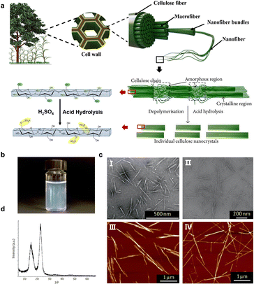 |
| | Fig. 1 (a) Schematic of the hierarchical structure of cellulose in a plant cell and the acid hydrolysis of CNCs. (b) A colloidally stable aqueous sulfuric acid-hydrolyzed dispersion. (c) Morphology of sulfuric acid-hydrolyzed CNCs from different biological sources: (I) softwood,42 Copyright 2018, Springer Nature, (II) sisal fibres,43 Copyright 2016, American Chemical Society, (III) bacterial cellulose, and (IV) tunicate cellulose.44 Copyright 2014, American Chemical Society. (d) XRD pattern of highly crystalline CNCs.49 Copyright 2002, American Chemical Society. | |
Geometrical characteristics report that CNCs generally show needle-like morphonology, with a few nanometers of width and the length ranging from tens of nanometers to several micrometers, which are associated with the biological sources (Fig. 1c).44,45 Typically, CNCs derived from wood or cotton are 3–5 nm in width and 100–200 nm in length, having the aspect ratio in the range of 10–30. CNCs from bacterial cellulose typically have lengths ranging from 0.5 to 2 μm and an aspect ratio of 30–100,44 while tunicates-derived CNCs have the largest length reaching 3.0 μm,46 coupled with the highest aspect ratio of 50–150.47 Since the acid hydrolysis treatment preferentially removes the amorphous regions, the left CNCs have a highly crystalline structure, as indicated by the characteristic diffraction peak at 2θ = 22.5° (Fig. 1d).48 On the other hand, the degree of crystallinity for CNCs varies between 55 and 90%,49 depending on the different cellulose sources. Additionally, the isolated crystalline cellulose is intrinsically birefringent.50 Such a birefringent feature can lead to the emergence of a local birefringence in materials where CNCs are orderly arranged, while it cancels out when CNCs are randomly dispersed.51,52 CNCs also exhibit excellent mechanical properties, with the axial tensile modulus reported to be ca. 130 GPa, high axial stiffness of about 150 GPa, and high tensile strength estimated at 7.5 GPa,53,54 being ideal candidates for the nano-reinforcement of composites.
According to the observations,55,56 CNCs composed of chiral D-glucose retain a certain degree of chirality, presenting a twist in both their internal structure and outer morphology, either as individual crystals or as bundles.57 Molecular dynamic simulations demonstrate that the primary cause of individual crystals twisting is due to the inter/intra-molecule hydrogen bonds, which lead to an advantageous energy effect.58 But the chirality mechanism of irregular CNC bundles is unclear. Fascinatingly, a recent study has revealed that these “bundles” function as chiral dopants, which bridge the gap in the hierarchical transfer of chirality from the molecular to the colloidal scale.59 Nonetheless, the mechanism underlying the transmission of chirality from the molecular scale to higher-order assemblies remains a subject of incomplete comprehension, and this complexity is further connected to the irregularities observed in top-down-derived CNC rods.
2.2 Cholesteric self-organization of CNCs
In 1959, Marchessault firstly reported the aqueous CNC suspension showing the birefringence feature and linked them to liquid crystals.40 Obeying the Onsager model, CNC suspensions show lyotropic liquid crystal behaviours above a threshold volume fraction.60 Typically, CNCs exhibit a random dispersion, resulting in an isotropic phase in a dilute suspension, while they prefer local mutual alignment to form anisotropic domains above a critical concentration.61 Such transition from isotropic to anisotropic is related to a trade-off between the rotational and translational entropies of individual nanorods. In 1992, Revol et al. found that CNCs could form a stable chiral nematic phase (i.e., cholesteric phase).62 Thus, the arrangement of CNC nanorods varied in a helical direction, in which they aligned and formed a long-range orientational structure. More significantly, they made a surprising discovery that the dried CNC films inherit the chiral nematic order from the colloid CNC suspension.63 Later, the evolution of a CNC suspension into a photonic film during evaporation-induced self-assembly process is proposed (as illustrated in Fig. 2).64
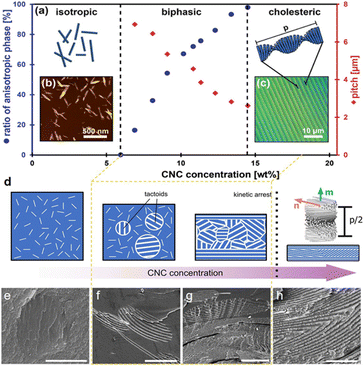 |
| | Fig. 2 (a–d) Schematic of the evolution of a CNC suspension upon increasing the concentration: from an isotropic state to the emergence of the cholesteric phase as tactoids, then a fully cholesteric polydomain structure that undergoes kinetic arrest and dries to form a helicoidal photonic structure.27 Copyright 2017, Wiley. SEM images showing the process of tactoids fused into the continuous cholesteric layers during drying:64 Copyright 2016, Springer Nature. (e) A newly formed CNC tactoid, (f) the initiation of fusion between two tactoids, (g) the sedimentation of CNC tactoids to the lower part, and (h) the formation of continuous layers. | |
Specifically, while drying the suspensions, CNCs undergo a first-order phase transition from the isotropic nanorods to small anisotropic droplets of slightly higher local concentration, referred to as tactoids (Fig. 2e),65,66via a nucleation-and-growth process. This process shows the coexistence of both isotropic and anisotropic phases in the intermediate regime. On continued drying of the suspension, these tactoids undergo growth process and then slowly fuse, sediment, and eventually merge into a continuous cholesteric texture (Fig. 2f and g).67 As the cholesteric phase further concentrates, the closely packed nanorods are sufficiently restricted in their ability to relax and rearrange their mutual position and orientation,68,69 reaching a kinetic stagnation that locks the cholesteric order in the proper position before the solid state (Fig. 2c, d and g).70 Thereafter, the continuous evaporation after the point of kinetic arrest induces a quasi-unidirectional compression to the cholesteric structure along the vertical axis, and finally the chiral structure of CNCs is completely locked in a specific position of the solid products after the water is completely evaporated (Fig. 2h).71 This process alters the pitch to the sub-micrometer range, which is critical to both the color and optical appearance of the resulting materials.
After drying, the assembled CNC presents a characteristic chiral nematic (cholesteric) ordering. Thus, the nanorods prefer an orientation along a common direction, n, which is modulated in a helical fashion along the axis m⊥n (as shown in Fig. 3). The distance along the helical axis that separates the nanorods of the same orientation after a 360° rotation is defined as the cholesteric pitch, p. The helix always exhibits left-handed chirality. Although researchers have struggled to understand the CNCs chiral origin, the precise mechanism of this phenomenon is still under debate.72 In essence, CNC chiral nematic structure belongs to a 1D crystal photonic. When the scale of p is located on the order of the wavelengths of visible light, the helical CNC organization leads to the Bragg reflection of light that is selective both in wavelength and polarization. The handedness allows circular polarization characteristic for the iridescent cellulosic films, which only reflected left-handed circular polarized (LCP) light and transmitted right-handed circular polarized (RCP) light when illuminated with the white light. Consequently, an extinction of observable color is detected when analyzed with a right-circular polarizer.
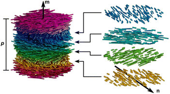 |
| | Fig. 3 Illustration of a cholesteric liquid crystal phase of densely packed CNCs. CNCs have local nematic-like ordering with a director n that rotates in a left-handed helicoid manner about the helical axis m. The cholesteric pitch, p, corresponds to a full 360° rotation of the director.31 Copyright 2023, American Chemical Society. | |
In fact, the composition of the initial CNC suspension alone is often not enough to define the final organization of CNC photonic structures. As a matter of fact, different factors at any stages of the CNC drying process strongly affect the final cholesteric organization to give unexpected results. The following sections give a comprehensive summary on regulating the cholesteric assembly of CNCs relying on diverse strategies, from aspects of both internal parameters and external factors.
3. Regulating the helical periodicity based on initial CNC suspensions
CNC helical arrangement is highly related to the initial state of the CNC suspensions, including the intrinsic features of the CNCs building block and the solution environment. These factors affect the equilibrium pitch of the cholesteric phase and further render a red or blue-shift in the final helical pitch, without disturbing the cholesteric arrangement of the CNCs themselves.73–75 This section discusses how the initial state of the CNC suspension to be tuned and further correlate that to the cholesteric behaviour of CNC suspensions, especially the nano-scaled pitch distance.
3.1 Intrinsic properties of CNCs building block
The optical properties of CNC helical arrangement are intrinsically linked to the helical pitch, which is very sensitive to the aspect ratio and surface charge of CNCs. According to the Onsager model,60 the critical concentration required to form the cholesteric phase is inversely related to the aspect ratio of CNC. The higher the aspect ratio, the lower the onset concentration (Fig. 4a). Exploiting the fractionation for biphasic suspensions under gravity, notably, CNCs with high aspect ratio transit into the cholesteric phase first, which offer both a stronger helical twisting power and an earlier phase separation that potentially extends the self-assembly window (Fig. 4b). This is in qualitative agreement with simulations of the self-organization of slightly helicoidal nanorods.76 The length and aspect ratio of the nanorods also have great influence on the strength of the interactions between the nanoparticles and their packing density (i.e., their volume fraction) as that dominating the cholesteric pitch. Commonly, for wood or cotton-based CNCs with small aspect ratio in the range of 10–30, drying their suspension results in vivid films with the pitch in the range of 200–300 nm (Fig. 4c, top).77,78 For bacterial cellulose-based CNCs with the aspect ratio in the range of 30–100 nm, their dried photonic films show red colour with the pitch distance extended to ca. 500 nm (Fig. 4c, middle).25 On the other hand, for tunicate-derived CNCs with the largest aspect ratio of 50–150 nm, they prefer to align in a parallel arrangement instead of cholesteric organization (Fig. 4c, bottom). On the contrary, however, another study reported a converse observation, which is that the larger CNC particles showed a smaller aligned pitch.79 They claim that the larger particles have stronger electrostatic force and reduced stiffness, thus making it easier for the CNCs to form a compact chiral nematic phase.
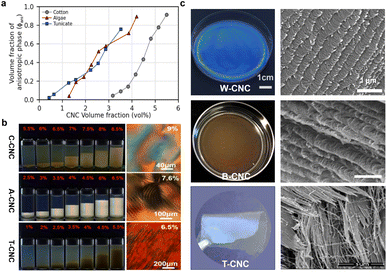 |
| | Fig. 4 (a) Comparing the phase diagram of cotton-derived CNCs (C-CNC), algae-derived CNCs (A-CNC), and tunicate-derived CNCs (T-CNC). (b) Photographs of C-CNCs, A-CNCs, T-CNCs suspensions at various concentrations under polarized light, and their corresponding POM images.80 Copyright 2018, Wiley. (c) Films dried from wood-derived CNCs (W–CNC), bacterial cellulose-derived CNCs (B-CNC), and tunicate-derived CNCs (T-CNC) and their fractured SEM images.81 Copyright 2021, Elsevier. | |
CNC surface chemistry dictates the interactions between nanoparticles and their local environment, further influencing their ability to self-organize. Reducing the surface charge is known to cause a great reduction in the pitch for CNC cholesteric organization.82 This primarily occurs due to the decrease in the surface charge, leading to a decrease in the electrostatic repulsions between the nanorods and a contraction in the Debye-Hückel length, thereby resulting in a closer stacking and stronger chiral interaction between the nanorods.55 Nowadays, many methods are applied to adjust the CNC surface charge while preserving the cholesteric self-assembly ability. For example, desulfation by heating offers an efficient way to reduce both the magnitude of electrostatic repulsion between CNCs and the range of their interactions,83,84 which has been reported to blue-shift the structural color of photonic CNC films.85,86 However, excessive desulfation compromises the colloidal stability of the CNCs and leads to aggregation before cholesteric ordering.87 On the other hand, polymer grafting is applied to CNCs to tune their surface charge, meanwhile contributing steric stabilization and preserving the ability to form a cholesteric mesophase.88 It has been demonstrated that these grafted nanocrystals display a lower pitch with a greater dependence on the volume fraction compared with bare CNCs.
3.2 Solution environment
Sharing a high similarity to that of the CNC surface charge affecting the pitch,82 the solution environment associated with the ionic strength has a significant impact on the pitch size. Increasing the ionic strength screens the CNC surface charges that reduces the thickness of the electric double layer, giving rise a reduction in the effective volume of CNC nanorods and thus contracting the pitch size. Electrolytes such as NaCl, HCl, and H2SO4 are commonly introduced into initial CNC suspensions to tune the ionic strength of the suspension. Care must be taken to ensure that the transient local increase in the ionic strength does not overshoot excessively, otherwise inducing CNC aggregation. Previously, Giese et al.72 added NaCl solution to CNC suspensions to tune the color of the resulting dried films, which changed from red to blue with increasing amount of NaCl. Thus, in the case of more NaCl loading, which provides higher ionic strength, the CNC surface charges are more screened. Consequently, the average chiral torque between CNCs is greater, leading to a smaller pitch. On the other hand, a solution environment with higher permittivity (εr) for CNC suspensions is beneficial to reduce not only the viscosity-normalized self-organization time but also the dependence of the equilibrium pitch on the CNC concentration and the final equilibrium value of the pitch. According to this, the exchange of water (εr = 80 at 20 °C) for other solvents such as formamide (εr = 111) or N-methylformamide (εr = 189) significantly reduces the pitches in the cholesteric CNC phase.89 Nonetheless, the underlying mechanism behind these observations is still unclear since the higher permittivity solvents have many effects on CNCs, including increasing the effective charge of the nanorods, meanwhile affecting the attractive van der Waals interactions and the hydrogen bond network between the CNCs.
4. Nano-scaled periodicity regulation by additives
4.1 Polymers
The replacement of water with neutral and water-soluble polymer additives can reduce the compression experienced by a kinetically-arrested cholesteric domain upon the complete loss of water,31 commonly giving rise to a shift in the colour for CNC chiral nematic films.90 In the section, we carefully study the influence of polymers on CNC chiral origination, emphasizing on the interactions between CNCs and different polymer additives. The representative polymers are discussed, including poly(ethylene glycol) (PEG), poly(vinyl alcohol) (PVA), hydroxypropyl cellulose (HPC), and polyvinylpyrrolidone (PVP).
4.1.1 Poly(ethylene glycol) (PEG).
Poly(ethylene glycol) (PEG), a depletion polymer agent in water,91 is the most common polymer incorporated with CNCs to modulate their self-assembly process and thus the periodicity of cholesteric organization. PEG can form depletion interaction with CNCs to induce the lateral association into well-organized bundles (Fig. 5a).92,93 With the loading content below 40 wt%, the adsorption of PEG on the surface of CNCs is responsible for pushing apart the CNC layers and increasing the helical pitch. When PEG loading is higher than 40 wt%, excessive PEG causes a sufficient magnitude of depletion potential, which expels PEG chains from the gap, leading to a phase separation.94,95 In this case, the actual amount of PEG intercalated between CNCs are less, hence rendering a smaller pitch, and the residual PEG is crystallized outside of the CNC layers.
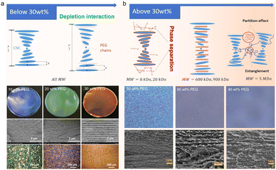 |
| | Fig. 5 (a) Schematic of polymer chains intercalating in the CNC layers when the PEG concentration is below 30 wt% (top) and the microstructure and optical property characterizations of the corresponding CNC/PEG composite films (bottom).74,75 Copyright 2017, Wiley. (b) Schematic of different MW polymer chains interacting with CNC layers when the concentration is above 30 wt% (top) and the microstructure of the corresponding CNC/PEG composite films (bottom).96 Copyright 2021, Elsevier. | |
Aside from the loading content, the interaction between PEG and CNCs is also related to the molecular weight of PEG. For low-molecular-weight (low-MW) PEG, charge screening effects are minimal, and the polymer is able to intercalate within the CNC structure. Medium- and high-MW PEG, however, are too large and instead domains of separated CNCs and polymer form, without significantly changing the ordering of the CNCs. Lin et al.96 modulated the transparency and the colour of the CNC/PEG composite films by varying the PEG molecular weight (Fig. 5b). Specifically, for low-MW PEG with a loading content of 30%, the CNC/PEG composites showed a maximum in pitch size and iridescent colour, and a blue shift in colour occurs when the PEG loading content is above 30%, consistent with Zhou's report.93 When incorporating high-MW PEG, the CNC/PEG composite films showed a constant increase in pitch dimension with increased PEG loading, without any “inflection point” of reflected wavelength or large-scale phase separation. This is due to the weakening of depletion interaction between high-MW PEG and CNCs.
4.1.2 Poly(vinyl alcohol) (PVA).
Poly(vinyl alcohol) (PVA) incorporated with CNCs to tune the helical periodicity is based on the strong hydrogen bonding interaction (Fig. 6a).97–99 Previously, Wang et al.100 successfully obtained CNC films with different photonic band gap and optical reflection with different contents of PVA loading from 0 wt% to 40 wt%, while excess of PVA over 50% renders an unstable cholesteric structure. Cohen et al.101 investigated the CNC assembly into a chiral nematic phase in the presence of highly hydrated PVA. They observed that with low PAV loading, the typical interparticle distance remained unchanged, while increasing the PVA concentrations caused the local (nematic) alignment to be completely lost, leading the suspended CNCs randomly to orient at the nanometric and micron-sized length scales. They suggested that the inter- and intramolecular hydrogen bonds between PVA and CNCs play a major role in the self-assembly of CNCs.102
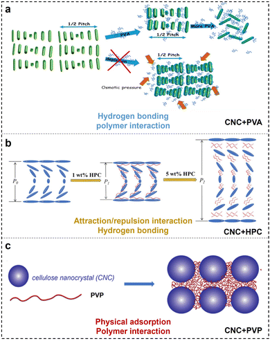 |
| | Fig. 6 Illustration showing the interactions between CNCs with different polymers: (a) PVA,101 Copyright 2019, American Chemical Society; (b) HPC,104 Copyright 2020, Elsevier; and (c) PVP,107 Copyright 2023, American Chemical Society. | |
4.1.3 Hydroxypropyl cellulose (HPC).
Hydroxypropyl cellulose (HPC) is a cellulose derivative, with some hydroxyl groups substituted by hydroxypropyl moieties.103 Before, Su et al.104 monitored the mesophase transition of CNCs in the presence of HPC. They observed that the composite CNC/HPC exhibits a dramatic blue shift in coloration with HPC incorporation from 0 wt% to 2 wt%, followed by a red shift with increasing HPC loading from 2 wt% to 7 wt%. No obvious reflective iridescence is detected at a further loading over 7 wt%. A small amount of HPC caused the CNC layers to adhere tightly and cushioned the electrostatic repulsive forces between CNCs as a result of compression of the layered distance, while a large amount of HPC have significant volume effect, which move nematic layers farther apart from each other, resulting in an increased interlayer spacing. Therefore, the attraction and repulsion between nematic CNC layers dominated by HPC are key factors that affect the cholesteric pitch (Fig. 6b). On the contrary, Saraiva et al.105 proposed that the hydrogen bonding between HPC and CNC has a great influence on the shift of the chiral nematic structure. In addition, MacLachlan et al.106 discovered that the effect of HPC on the self-assembly of CNCs is WM-dependent. High-WM HPC shows a larger increase in the helical pitch for CNC cholesteric organization as a function of HPC concentration compared to low-WM HPC. The author postulated that as the polymer enters this entangled regime and occupies a larger volume space, polymer chain dynamics is the main driving force for differences in chirality. Based on the above, research into understanding the co-assembly of CNCs with HPC additives remains conflicting, and a more comprehensive understanding of CNC–polymer interactions during co-assembly is necessary.
4.1.4 Polyvinylpyrrolidone (PVP).
Polyvinylpyrrolidone (PVP) has been used as an additive in the CNC self-assembled architecture. Andrew et al.107 observed a behaviour consistent with the adsorption of PVP onto the CNC surface (Fig. 6c). Furthermore, CNC self-assembled nanostructure can be well maintained even with the PVP loading content up to 70 wt%.108 Such high order–disorder transition point is the top value in CNC/polymer composites, exceeding 50 wt% in CNC/PVA,109 7% in CNC/HPC,104 and 40 wt% in CNC/PEG93 systems. It has been well reported that the presence of PVP has a negligible effect on CNC chiral nematic ordering.110 This is ascribed to amorphous and neutral PVP that has a weak influence on the CNC surface charge, which is important for maintaining its self-assembly. Instead, the adsorption of PVP onto the CNC surface introduces “spacers” in between particles that extend the helical pitch (Fig. 6c).
4.2 Small neutral molecules
In comparison to polymers, small neutral molecules as additives to tune CNC self-assembly have the following advantages: much easier to insert into CNC cholesteric structure, more accurate to control CNC pitch, and better compatibility with CNCs. A common small molecule additive, i.e., D-glucose, is often applied to co-assemble with CNCs. Before, Mu et al. used D-glucose to control the pitch of chiral nematic CNC suspensions.111 The introduction of D-glucose had no effect on the anisotropy of the liquid crystal phase and the self-organization of CNCs, while it showed varied influences on the helical structure at different stages upon casting CNC films. Specifically, the chiral dextro-D-glucose enhanced the twisting effect of the rod-shaped CNCs, leading to a reduction in the pitch of the liquid crystal structure. On the contrary, at the gelation stage of the CNC suspension, D-glucose acted as a dispersant that increases the suspension viscosity and hence prevented the pitch from being further reduced. Lastly, the incorporation of non-volatile D-glucose prevents the CNC concentration from reaching 100 vol% and therefore reduces the final compression of the CNC mesophase in common. Therefore, the film pitch is larger than that found for an additive-free film, presenting a red-shift in the reflected color in common.
4.3 Nanoparticles
To date, many kinds of nanoparticles with a size similar to CNCs and additional functionalization have been introduced into CNC cholesteric organization to accurately regulate the pitch. Metallic nanomaterials, which possess a unique size effect and optical activity,112 including oxides of silver,113 gold,114 copper,115 iron,25 titanium,116 and zinc,117 have been applied to prepare composite photonic materials with excellent optical properties. For example, Liu et al.118 prepared CNC/silver nanoparticles (AgNPs) chiral composite films with the reflection wavelength shifted from 475 to 773 nm, while the loading amount of cationic AgNPs was reduced from 8% to 2%. In another study, gold nanorods (GNRs) were combined with CNCs to prepare chiroptical plasmonic films (Fig. 7a).114 It was demonstrated that with the GNR loading below 0.93 wt%, the entire composite film had a chiral nematic structure, while progressive disappearance of the chiral nematic structure occurs with increasing NR content (Fig. 7b–d). With the highest GNR loading of 3.39%, only a small fraction of the film exhibited a chiral nematic structure (Fig. 7d). Aside from metal oxides, nanocarbon materials such as 0D carbon quantum dots (CQDs) with a typical nanoscale material with particle sizes < 10 nm could match well with the CNCs. Small-sized CQDs could get into the chiral nematic organization of the CNCs that expands the helical pitch, meanwhile allowing the luminescence for their hybrid films (Fig. 7e and f).119 Additionally, 2D graphene oxide (GO) with oxygen functionalities is also incorporated with CNCs for their co-assembly, with the highest loading of about 2.0%. However, the self-assembly behaviour of CNCs may be disturbed when the loading of GO is changed.
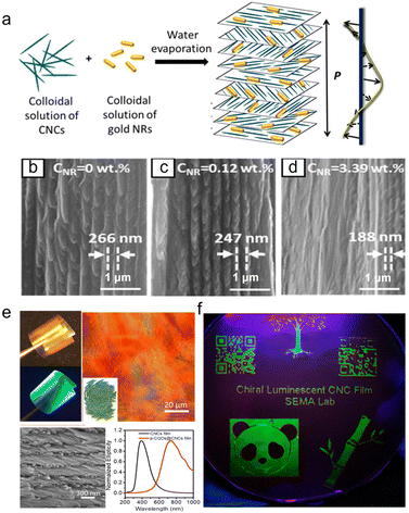 |
| | Fig. 7 (a) Schematic of the preparation of the composite chiroptical plasmonic film by mixing aqueous suspensions of CNCs and GNRs. Representative SEM images of the cross-section of the CNC/GNR films at NR concentrations of (b) 0, (c) 0.12 wt%, and (d) 3.39 wt%.114 Copyright 2014, American Chemical Society, (e) Characterization of the chiral luminescent CQDs/CNCs film: POM image, SEM image, and CD spectra. (f) Patterned chiral luminescent CQDs/CNCs films with 10 cm diameter at 365 nm UV light.119 Copyright 2019, American Chemical Society. | |
5. Micro-scaled alignment manipulation with external forces
External forces such as ultrasonication, mechanical shearing,120 magnetic field,121 and electrical field122 are applicable to manipulate the photonic alignment and orientation of CNCs. Amongst these, ultrasonication treatment is easy to conduct, which mainly affects the spiral periodicity of CNC chiral nematic organization. The mechanical shearing and electric or magnetic field have significant influence on the alignment manner of CNC nanorods upon the assembly process. Specifically, with mechanical shearing, CNCs can be modestly oriented,123 while the oriented nanorods are prone to relax once leaving the shearing field. Electric field can trigger a high alignment for CNCs. However, electric field-induced CNC alignment relies on a high voltage and it is only applicable to nonpolar liquid phase in which CNCs are difficult to uniformly disperse.122 Though magnetic field offers a feasible technology to control CNC orientation in bulk suspensions, it commonly requires a very strong magnetic field, which technically limits scalable processing. Based on the above, this section systematically discusses the effectiveness, practicality, and limitation of different external forces applied for CNC alignment.
5.1 Ultrasonication
In addition to the initial stage of CNCs suspensions and the introduction of additives, the physical external forces can dramatically affect the self-assembly process of CNCs and thus the optical properties of the CNC photonic materials. Typically, ultrasonication associated with “cavitation effect” has influence on the pitch of CNC cholesteric organization. As demonstrated by Beck et al.,124 they observed that the reflected wavelength of the dried film shifted toward the red wave direction with the ultrasonic vibration of the CNC suspensions. Later, Liu and colleagues systematically investigated the influence of ultrasonication time on the modulation of the pitch of chiral nematic liquid crystals.125 They found that the cholesteric pitch increased with more applied energy by prolonging the ultrasonication time. A recent study by Vignolini's group59 showed that tip sonication can effectively decrease the size of nanorods and alter their aggregation state, ultimately impacting the pitch. Despite the significant advancements in studying the effects of ultrasonication, the mechanism remains unclear.
5.2 Shearing
Hydrodynamic shear is available to align CNCs in suspensions.126–128 Different approaches including blade-coating,129 shear-coating,130 and spin-coating131 are employed to tune the shear-induced orientation of CNCs. Understanding the shear alignments on the microstructure is essential for manufacturing CNC films with advanced optical properties. In fact, the shearing alignment of CNCs is highly related to the suspension concentration as well as the shearing force.132 Commonly, under the unidirectional shear flow, isotropic CNCs prefer to orient with the direction normal to the shear plane at a low rate, while high shear disrupts the helicoidal order of cholesteric CNC phase, giving rise to an alignment parallel to the shear direction.133 Therefore, the shear-induced alignment of CNCs generally form a nematic organization instead of control over the CNC cholesteric structure. On the contrary, Park et al.134 introduced a circular shear flow in the CNC suspension during drying, which exceptionally imposes a uniform helix orientation even in the case of initially isotropic CNC suspensions. The authors claimed that the tactoids are distorted into an ellipsoidal shape under the left-handed shear flow. This breaks the symmetry of spherical tactoids prior to the phase transition, which thus imposes a direction for the helix to follow, namely, along the shortest axis of the ellipsoid to minimize the energy. In this way, the circular shear flow can thus ensure a uniformly aligned vertical helix. Recently, Tian and co-workers135 regulated the helical structure of CNCs under a left-handed circular shear flow with different rotational rates. They observed that in the isotropic phase, the chiral nematic droplets with helices normal to the shear direction are formed initially. In this stage, a slight distortion induced by the shear flow is insufficient to reorient the helices.134 With the liquid crystal phase developed with a high initial concentration, uniformly standing helices are promoted by the glass substrate. Thereafter, the further drying of the solvent caused the viscosity to increase, which inhibits the relaxation of CNCs. Consequently, CNCs are prone to being forced to follow the direction of shear flow to allow a uniformly aligned vertical helix.136
5.3 Magnetic field
It is well-known that individual CNCs show intrinsic anisotropic diamagnetic susceptibility.50 For this reason, magnetic field-induced alignment offers a feasible technology to control CNC orientation in the bulk suspension. The response of liquid-crystalline CNCs in a magnetic field differs depending on the suspension concentration. Below the critical concentration, CNCs orient linearly perpendicular to the field to form long-range uniaxial (nematic) order only under a very strong enough field.137 Above the critical concentration, the magnetic field can stabilize and orient the cholesteric order into a macroscopic monodomain (Fig. 8a).138 Specifically, with magnetic field, the anisotropic tactoids are preferentially reoriented with the helical chiral nematic director parallel to the magnetic field, and again individual CNCs in the tactoids are oriented perpendicular to the field.139 This results in a uniform chiral nematic texture.140 Compared with the static magnetic alignment, differently, rotating magnetic fields induce the parallel orientation of the nanorods to untwist the cholesteric phase, leading to a nematic order normal to the field.141–143 For the magnetic alignment of CNCs, previously, strong magnetic fields (as high as 28 T) were commonly applied to create highly aligned CNCs.46 This seemingly limits the applicability and thus the relevance of this technique to produce aligned CNC-based materials. Later, moderate magnetic fields (0.5–1.2 T) successfully induced the alignment of the cholesteric CNC phase. The orientation of CNCs in low magnetic fields is due to the cooperative effect in their cholesteric arrangement. Significantly, Frka-Petesic et al.121 used small commercial magnets as a powerful tool to manipulate the orientation of the cholesteric domains. They produced solid nanostructured films with improved uniformity in the cholesteric pitch and orientation by adjusting the spatial configuration of the magnet with respect to the drying suspension (Fig. 8b–d) or even a simple route to patterned films using more complex magnet geometries (Fig. 8e). Furthermore, they demonstrated the possibility to specifically orient the cholesteric structure either vertically or away from the usual planar orientation into specific directions. The film prepared in the presence of a tilted magnetic field shows a locally homogeneous cholesteric monodomain but with a clear tilt with respect to the film–air interface (Fig. 8f). Surprisingly, the film structure dried directly above the junction between the two magnets displays a clear zig-zag pattern (Fig. 8g). The authors claim that a such pattern formed due to the mechanical buckling of the cholesteric structure upon unidirectional vertical compression perpendicularly to its helix axis m. Beyond the magnetically-controlled orientation of CNCs, Wang et al.144 realized the position control of CNCs tactoidal microphases with magnetic field (Fig. 8h). Based on the exclusion effects of tactoids on superparamagnetic doping nanoparticles, they differentiated the ordered tactoids and isotropic nanocrystals in the CNC suspensions by volumetric magnetic susceptibility. In this way, they could achieve position and orientation control of liquid crystalline tactoids by magnetic field gradients. Additionally, our previous work25 reported the magnetically steerable uniform photonic organization of CNCs (Fig. 8i). With a very weak magnetic field below 150 mT, we enabled the transformation of CNC alignment from helicoidal cholesteric to uniaxial nematic phase with near-perfect orientation order parameter of 0.98 across large areas. Furthermore, the magnetically triggered high shearing rate of circular flow has been demonstrated as the main cause that facilitates the unconventional unidirectional orientation of nanocrystals along the gradient magnetic field and untwisting helical organization.
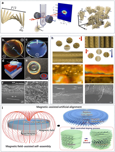 |
| | Fig. 8 (a) Ordered CNC tactoids aligned with a helical axis with respect to the magnetic field.138 Copyright 2016, American Chemical Society. (b and c) Examples of films that were cast spanning two magnets, as indicated by the schematic in (d). (e) Exotically patterned films can be obtained when casting on a patterned polydomain magnet displaying opposite magnetization direction on the same face. (f) SEM of the cross-sections of CNC films prepared: (f) in a tilted magnetic field (H), and (g) in a nearly horizontal field.121 Copyright 2017, Wiley. (h) Phase Separation of Magnetite Nanoparticle-Doped Lyotropic Liquid CNCs (left) in only the presence of gravity and (right) in a vertical gradient magnetic field. Furthermore, the corresponding POM images (scale bar: 50 μm) and SEM images (scale bar: 10 μm).144 Copyright 2019, Cell Press. (i) Schematic of magnetic film formation in the presence of a magnetic field and formation of unidirectional nematic ordering that replaces tactoids with chiral nematic organization.25 Copyright 2022, Springer Nature. | |
5.4 Electric field
Electric field is an easily implemented tool to induce an alignment of anisotropic particles in a suspension.145,146 For the first time, Bordel et al.147 provided the evidence of the possibility of cellulose orientation under an electric field. They observed that both ramie fiber fragments and cellulose whiskers could be oriented parallel to the electric field, which might be originated from either a positive dielectric anisotropy and/or from the form of birefringence arising from the elongated shape of the particles. Habibi et al.148 observed an oriented nematic ordering of individual CNCs when drying a CNC suspension on a micron-scaled electric junction. Thereafter, the remarkable reorientation of CNCs under electric field is evidenced by Heux and co-workers.149 They revealed that this reorientation is highly related to the presence of both permanent and induced dipole moments on individual CNCs. Furthermore, Frka-Petesic et al.122 applied electric field as an efficient and convenient tool to control the iridescence properties of concentrated CNCs in an apolar solvent (Fig. 9). They successfully control the orientation of the cholesteric phase under a low electric field, tune the iridescence under intermediate fields, and produce a purely nematic phase at higher fields. They demonstrated that the electric field not only allows a precise tuning of the pitch but also enables sample homogeneity at the macroscopic scale, hence allowing the dynamic control of the structural colours.
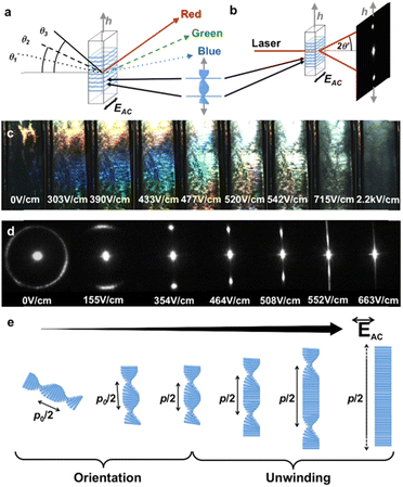 |
| | Fig. 9 (a and b) Schematics illustrating the iridescence and laser diffraction as effects of the same light diffraction caused by the underlying cholesteric structure. (c) Iridescence evolution of a polydomain cholesteric sample upon first electric field application, displaying an increase in light intensity, red shift and, finally, color disappearance. (d) Evolution of the laser diffraction pattern upon electric field increase, showing cholesteric orientation, pitch increase and, finally, complete cholesteric unwinding. (e) Schematic of the sequential cholesteric orientation and unwinding upon electric field increase.122 Copyright 2017, Wiley. | |
6. Photonic stacking with multi sizes
6.1 Biphotonic structure
In nature, striking and bright color generated from the multiple photonic–photonic colour mixing effect. For example, flowers like the tulip Queen of the Night displays bright color due to the wavelength-selective absorbing pigments combined with the light-scattering effect generated by the long-range periodic surface striations.150 In another case such as beetles,151 the metallic green colour results from the combination of helical fibrous chitin with periodic blazed diffraction grating-like surface structures. This yields morphology-induced light scattering coupled with the helical matrix-derived structural colour. The fabrication of nano-scale structures on a large area with the additional control on their micro-scale morphology152 is very demanding to develop novel materials with advanced optical properties. In this regard, previously, Chu et al.153 reported a series of floral-mimetic cholesteric wrinkled films (CWFs) using CNCs as the photonic ink to cast onto a wrinkled poly(dimethylsiloxane) (PDMS) mould. After evaporation, the dried film possesses the helical cellulose matrix with long-range ordered wrinkles that imprinted from the template on the surface (Fig. 10a–d). The cholesteric ordering in the bulk phase and the grating-like photonic surface together yield a biphotonic architecture (Fig. 10e). As a result, the interplay between such two photonic structures lead to the selective scattering of circularly polarized light with specific handedness. Further, they demonstrated the possibility to engineer photonic colour in a custom-made cellulose paper based on the chiral nematic organization and surface topography.154 Consequently, the as-prepared cellulose paper shows striking colour appearance arising from the selective Bragg reflection as well as the further scattering of LCP light, which is related to the hierarchical structure. This shares a programmable photonic–photonic coupling very similar to the exocuticle of Chalcothea smaragdina. In addition, Xiong et al.155 fabricated patterned CNC films, which have the interior ordered helicoidal structures and the highly oriented CNCs gratings at the top-most layer (Fig. 10f). It turns out that the as-fabricated films exhibited brilliant and angle-dependent structural colours with a narrow, selective reflection band and enable the diffraction pattern (Fig. 10g and h). Further, they demonstrated that combining arrays of 2D photonic crystals and 3D microlens photonic elements onto chiral CNC films is an efficient strategy to control the selective light reflection and circular polarization light propagation with highly asymmetrical circular dichroism.
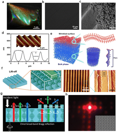 |
| | Fig. 10 (a) Photograph and (b) surface SEM image of the cholesteric wrinkled films, showing bi-structural colour and periodic surface wrinkles similar to those of floral petals. (c) SEM image of a cracked cholesteric wrinkled film showing porous layered structure under the wrinkles. (d) AFM image and numerical analysis of the cholesteric wrinkled films. (e) Illustration of the hierarchical structure of the cholesteric wrinkled films.153 Copyright 2019, Cell Press. (f) Assembly of chiral CNC photonic structures with surface gratings, and topographical AFM image of CNC grating surfaces with highly aligned CNC ordering within trenches. (g) Schematics of enhanced circularly polarized light from CNC films with grating structures. (h) Diffraction pattern by the CNC film.155 Copyright 2020, Wiley. | |
6.2 Sandwich photonic structure
It is well known that CNC helicoidal structures selectively reflect LCP light and allow the transmission of RCP light, showing a circular polarization feature. It means that the theoretical optical performance of traditional CNC-based photonic materials is limited to 50%. Very interestingly, other photonic structures capable of reflecting both RCP and LCP light exist in nature, as found in the cuticle of 156 This is due to a structure that exists in its cuticle, which consists of an anisotropic domain, functioning as a half-wave phase retarder sandwiched between two left-handed cholesteric layers.157 Inspired by this sandwich photonic structure, for the first time, Fernandes et al.158 fabricated a new cellulose-based photonic structure consisting of an anisotropic layer sandwiched between two left-handed cellulose cholesteric domains with different pitches (Fig. 11a), which is achieved by simply inserting a nematic liquid crystal layer of 4-cyano-4′-pentylbiphenyl (5CB) between two left-handed cholesteric domains. The middle 5CB layer acts as a λ/2 retardation plate capable to change the RCP into the left-handed one. Specifically, the LCP component of natural light is selectively reflected by the first cholesteric-like film, through which its right-handed counterpart is transmitted and then converted into left-handed circular polarization mode by the nematic like a half-wave retarder, followed by reflection from the second cholesteric-like layer. As a result, the resulting films can reflect simultaneously RCP and LCP light (Fig. 11b). Based on this, De La Cruz et al.159 boosted the reflection coefficient to nearly 100% by designing three-layer sandwich photonic structures that consist of two left-handed cholesteric films separated by an optical retarder. This reflection is also tuneable and can be achieved in the near-infrared range, which expands the application of biomaterial cellulose nanocrystals in the field of thermal management.
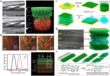 |
| | Fig. 11 (a) SEM images of the CNC film with the gap filled with an anisotropic liquid crystal of 4CB, and the scheme showing the gap filled with the anisotropic layer sandwiched between the two left cholesteric domains. Scale bars: 3 μm. (b) Photographs of the CNC and 5CB composite film observed through unpolarized white light and circularly polarized light showing different colour reflection in LCP and RCP light channels (top), and the optical characteristics of the film with a liquid-crystal layer acting as a λ/2 plate (bottom).158 Copyright 2017, Wiley. (c) Scheme of CNC–CNF stacked biocomposite films fabricated from alternating layered chiral nematic CNC and random CNF phases. (d) Cross-sectional SEM image showing multi-layer stacking structure. (e) Strength and toughness of the CNC–CNF stacking structure.76 Copyright 2020, American Chemical Society. | |
6.3 Multi-layered photonic stacking
To date, to overcome the mechanical brittleness issue for CNC photonic materials, main efforts focus on developing multiphase bio-enabled materials and structures by directly blending CNCs with the additives, followed by evaporation-induced drying. The introduction of additives enhances the mechanical flexibility but unfortunately disturbs the uniform helicoidal organization of CNCs and ultimately causes a collapse in photonic-capable organization. Attaining high mechanical performance for chiral nematic photonic structure without compromising the vivid optical iridescence is a challenging task. In this regard, previously, our group reported robust multi-layer photonic laminate with an alternatively stacked chiral nematic CNC phase and a random cellulose nanofiber (CNF) phase via layer-by-layer strategy (Fig. 11c).76 The resulting composite films show a perfect laminated stacking morphology (Fig. 11d), where CNC and CNF layers are closely packed with discrete interfacial boundaries, and the CNF layer can be easily identified with a “squashed” layer sandwiched between two CNC layers with oriented helicoidal morphology. Such multi-layer photonic stacking possesses many-fold enhancement in both mechanical strength and toughness (Fig. 11e), meanwhile well maintaining the optical effects of individual layers, i.e., the vivid structural color generated from the helicoidal organization of the CNC layer and the excellent transparency enabled by the CNF layer.
7. Macro-optical materials with varied geometries
7.1 Two-dimensional (2D) films
For CNC-based optical materials, the simplest example of geometrical confinement is the production of 2D thin films, which are generated from the evaporation of a small volume of CNC suspension in a Petri dish.160 In this case, a planar orientation of the cholesteric nanostructure with helical axes perpendicular to the surface is commonly obtained. Exceptionally, MacLachlan's group161 prepared sheet films with the helical axis of the chiral nematic structure parallel to the film surface. Such an arrangement is achieved by confining the self-assembly of CNCs in a vertically-oriented narrow chamber with the assistance from the cooperative effects of gravity on phase separation and a strong magnetic field for the uniform alignment of the chiral nematic liquid crystal (Fig. 12a). For now, diverse aspects of photonic films have been made in terms of their fabrication and functionalization; unfortunately, the traditionally self-assembly process in the Petri dish is limited to the small millimeter scale for CNC photonic films. For this regard, very impressively, Silvia Vignolini's group162 demonstrated an industrially relevant route to scale-up the production of structurally coloured CNC films using a commercial roll-to-roll (R2R) coating unit (Fig. 12b). By optimizing the parameters affecting the self-assembly upon R2R process, the author could produce structurally coloured films in succession (Fig. 12c and d). Recently, our group77 successfully constructed metre-scale chiroptical CNC films via the hierarchical assembly of CNCs on the topography-tailored textile (Fig. 12e). In this case, the featured textile substrate as the template allows CNC chiral-nematically assembled along the topographical surface. This generates templated CNC photonic “cast” in situ tessellated onto the textile surface, which thereby facilitates the scaling-up capability for chiroptical CNC films.
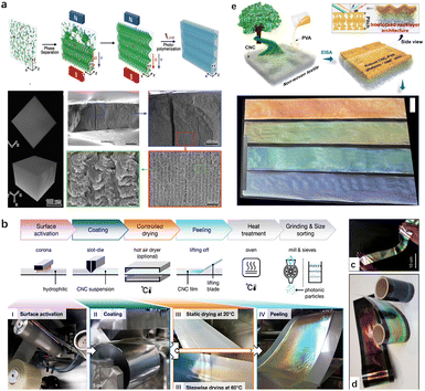 |
| | Fig. 12 (a) Schematic representation of the formation of the optical grating hydrogel sheet film and their microstructure.161 Copyright 2020, Wiley. (b) Overview of the R2R processing of a CNC suspension into photonic films. (c) Red, green and blue R2R-cast CNC films deposited onto a black PET web. (d) Free-standing R2R-cast CNC film.162 Copyright 2021, Springer Nature. (e) Schematic of hierarchical cholesteric assemblies onto featured nonwoven textile surface, and the obtained meter-scaled textile-supported chiroptical CNC films.77 Copyright 2023, American Chemical Society. | |
7.2 Zero-dimensional (0D) photonic microparticles
Aside from the traditional 2D film, researchers have paid considerable attention to combine the cholesteric organization with more complex geometries to broaden the optical properties of macroscope CNC photonic materials. The self-assembly of CNCs has been confined in 0D spherical geometry (i.e., droplets), which is based on the emulsification of cholesteric CNC microdroplets in immiscible oil163,164 to prepare hierarchically structured microparticles with a distinct chiral nematic morphology. For example, Vignolini's group51 fabricated a nanostructured microparticle from the progressive loss of solvent from a dilute CNC droplet (Fig. 13a), during which phase transition occurs and the CNCs self-organize into a Frank–Pryce cholesteric architecture. MacLachlan's group, for the first time, investigated the growth of the liquid crystals from tiny tactoids to droplets with spherical symmetry163 and proposed that the chiral nematic bands of a CNC tactoid in a microdroplet grown along the water–oil interface. Later, Kumacheva's group165,166 observed that with progressive confinement, phase separation occurs within cholesteric CNCs droplets, which then evolved into a micrometer-size isotropic core and a cholesteric shell formed by concentric nanocrystal layer. It is further demonstrated that the hierarchical structure of cholesteric spherical droplets is highly related to their size scale. Specifically, for droplets with radius below 150 μm, the planar anchoring at the liquid–liquid interface not only enables the cholesteric phase to assemble into a monodomain Frank–Pryce architecture over the whole droplet surface167,168 but also generates radial disclinations that connect the isotropic central core comprised by the topological defect. However, on the contrary, the smaller droplets (radius of <40 μm) have the core formed by a central tactoid, which is surrounded by a thin Frank–Pryce shell. Despite these successful attempts on the self-assembly of CNCs confined within the emulsified spherical droplets, the resulting microparticles fail to present structural colour in the visible range due to the large pitch inherent to spheroidal CNC microparticles, which resulted from the reduced compression upon CNC self-assembly confined in spherical confinement. For this reason, Parker et al.169 introduced the interfacial buckling to provide additional pitch compression during the confined self-assembly of CNCs droplets (Fig. 13b). This produces structurally coloured cellulose photonic particle pigments, which can reflect colour across the full visible spectrum (Fig. 13c). Very interestingly, for the first time, Geng et al.170 dried the cholesteric CNC suspension shells instead of droplets by confining the fully liquid crystalline suspensions of high aspect-ratio CNCs between immiscible hexadecane oil phases (Fig. 13d), in this case generating spherically shape cholesteric shells that rapidly anneal with uniformly radial helix orientation (Fig. 13e and f). The internal oil droplet minimizes radial shrinkage and maximizes helix pitch compression simultaneously. This facilitates the production of solid CNC microparticles, which features the spherical curvature and the radial helix with sufficiently short pitch, consequently forming cholesteric spherical reflectors to allow striking visible retroreflection.
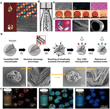 |
| | Fig. 13 (a) Images of the microfluidic water-in-oil droplets and the dried CNC microparticle under cross-polarizers, and the helicoidal assembly within the dried particle.51 Copyright 2016, American Chemical Society. (b) Schematic showing the preparation of photonic microparticles, and the SEM images of a microparticle prior to and after treatment with methanol, showing the volume contraction and increase in buckling. (c) Photographs showing red, green, and blue cellulosic photonic pigments and their dark-field microscopy images in refractive index oil.169 Copyright 2022, Springer Nature. (d) Microscopic photo of shell production using nested glass capillary microfluidic device. Black and orange arrows indicate oil and CNC suspension flows, respectively. (e) Shells with good alignment, and side views of a shell with dyed inner phase during drying. Scale bar: 50 μm. (f) POM and SEM images of dried CNC shells.170 Copyright 2024, Wiley. | |
7.3 One-dimensional (1D) photonic fibers
Compared with fully enclosed spherical geometries, continuous cylindrical geometry with an infinitely extended axial-symmetrical space is an amazing cholesteric liquid crystal configuration. 1D fibers with self-assembled photonic structures are of special interest for their unique photonic properties. Previously, for the first time, Meng et al.171 designed and fabricated CNC-based fibers through a simple wet-spinning process, in which the CNCs act as the photonic matrix with PVA as the additives to the help in fiber shaping as well as tuning the photonic properties. For fiber production, high-concentration CNC/PAV composite spinning solution was extruded from a plastic syringe into an ethanol coagulating bath. During the spinning process, CNC phases tend to be helically arranged along the long axis of the macroscopic fiber, forming a twisted organization but with a low ordering. Later, Wu's group172 developed a new breed of liquid metacrystal (LMC) fibers through the self-assembly of CNCs within an in situ formed hydrogel sheath using a simple microfluidic strategy (Fig. 14a and b). For fiber preparation, the key challenge for creating a continuous and smooth microtubule of CNC assemblies is to suppress Plateau–Rayleigh instabilities173 of the ejected stream. For this issue, a robust hydrogel sheath formed by the fast gelation of sodium alginate and Ca2+ ions are introduced,174 which contributes to fluid shear stress concentrated on the surface of the ejected stream near the nozzle (Fig. 14c), giving rise to counter shape change as well as provide a stable and continuous assembly environment. After fabrication, the CNC cholesteric alignments within the colloidal core are determined using POM and CD spectroscopy (Fig. 14d–f). Furthermore, the POM images (Fig. 14g and h) of the radial direction shows the distinct Maltese cross pattern and the corresponding radial section of the LMC fibers show the circularly symmetrical structures (Fig. 14i), corresponding to the radial topological configuration. Overall, the obtained liquid crystal fibers show complex hierarchical architectures across different length scales, including long-range cholesteric order, 3D topological defects, and core-sheath architectures (Fig. 14d and e). This work paves a new way to develop the length-scale colloidal organization with continuous and stable topologies. However, the as-fabricated CNC cholesteric fibers only show vivid interference colors under a polarizer. The construction of structural colored cholesteric fibers is still a great challenge.
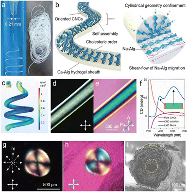 |
| | Fig. 14 (a) Photographs showing the uninterrupted generation of LMC fibers. (b) Schematic depicting the formation of the cholesteric phase within the LMC fibers in a generation process and the self-organization principle of LMC fibers in a dynamically confined, cylindrical geometry. (c) Simulated shear stress field distribution on the surface of LMC fibers. (d and e) POM image of right-tilted LMC fibers under crossed polarizers. Scale bar: 500 μm. (f) CD spectra of pure CNCs, injection solution, and the LMC fibers. (g and h) POM images of the radial section of LMC fibers with a Maltese cross pattern. (i) SEM image of the radial section of LMC fibers with a concentrically-ringed structure. The yellow dashed line in (i) illustrates the aligned direction of LMCs.172 Copyright 2020, Wiley. | |
7.4 Three-dimensional (3D) photonic aerogels
Additionally, imparting chiral nematic structure into a 3D architecture, like an aerogel, would allow CNC optical materials with promising novel applicability in material science. Previously, Chu et al.175 constructed hierarchical long-range structured aerogels by the unidirectional freeze-casting of liquid crystalline CNCs (Fig. 15a). They proposed that during the directional freezing process, the difference in the growth speed of ice crystals in length and thickness generates a flowing that induces CNCs aligned in a direction parallel to the movement of the freezing front. Specifically, for the isotropic CNCs suspension, the shear pressure developed in the squeezed film effectively aligns and traps the rod-like CNCs into a nematic orientation with an ordered state (Fig. 15b). For the dense liquid crystalline CNCs on directional freezing, the resulting shear flow can align the fluid CNCs liquid crystals into a lamellar arrangement (Fig. 15b), with the formation of ice crystals between them. These orientations can be preserved by the sublimation of the ice template. Later, MacLachlan's group176,177 prepared aerogel materials with periodic structures derived from chiral nematic liquid crystalline CNCs through critical point drying of an alcogel of CNCs (Fig. 15c). Moreover, the chiral nematic CNC aerogel was extended to the fabrication of periodic silica/cellulose aerogel, silica aerogel, CNC/GeO2 composite aerogel, and the carbonized carbon aerogel with well-maintained chirality. Nonetheless, for these CNC chiral nematic aerogels, the helical pitch is tens of micrometers, far from the wavelength range of visible light, consequently restricting the application of CNC aerogels in photonic materials. In this regard, MacLachlan’ group178 fabricated pressure-responsive chiral photonic aerogels by combining liquid crystal self-assembly of CNCs with the ice-templating processes (Fig. 15d). The authors claimed that during the freeze-drying step, the ice crystals not only act as template for the macropores within the final aerogel 3D network but also compress the helical pitch of the CNC liquid crystal phase. Consequently, the resulting aerogels feature a hierarchical structure in which the primary 2D chiral nematic structured walls of cellulose nanocrystals form ribbons that support a secondary 3D cellular network. Such a hierarchical structure combined with the flexibility enables the 3D structure of the aerogel that can easily be transformed to a dense 2D structure by pressure-induced rearrangement, upon which the pressure-responsive photonic aerogel converts from a light scattering to a vivid structure colour.
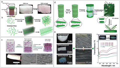 |
| | Fig. 15 (a) Schematic of the directional freeze-casting for CNCs suspension and photographs of the CNCs-ice monolith and CNCs aerogel. (b) Schematic of the ice-assisted hierarchical self-assembly approach of CNCs in isotropic and anisotropic phases, respectively.175 Copyright 2017, American Chemical Society. (c) Schematic for the formation of a CNC aerogel, and the cross-section SEM images revealing its layered periodic structure with lefthanded chiral nematic order.176 Copyright 2018, the Royal Society of Chemistry. (d) Formation of pressure-responsive chiral photonic aerogels, and (e) their pressure-responsive characterization: the change in the color appearance, microstructure, and transmission UV-vis spectra for chiral photonic aerogels before and after compressing.178 Copyright 2019, Wiley. | |
Conclusion and outlook
CNCs as versatile and sustainable nanomaterials are drawing increasing attention to offer a renewable, biodegradable, and biocompatible route to develop artificial functional materials with diverse applications such as structural coloration and optics arise from their ability to self-organize into chiral nematic structure via the evaporation-induced assembly process. Manipulating the assembly behaviour and hence controlling the alignment of nanorods and the orientation of the cholesteric helix are fundamental to design defect-free CNC-based optical grade materials, which demonstrate great potential towards applications including security labelling, soft actuator, and shape morphing, remote communication and visual sensing.
As a matter of fact, each of the intermediate steps upon the cholesteric self-organization process, from hydrolysing cellulose, to isotropic CNC nanoparticles, cholesteric liquid crystal, kinetic arrest and ultimately drying, can be readily manipulated by a diversity of intrinsic and extrinsic factors as that to control the eventual photonic structure. In this review, we summarize the current research frontiers on the modulation of CNC photonic structure with diverse aspects of strategies from the perspectives of the intrinsic features of bulk building block, solution environment, extra additives, and external forces. Importantly, the influences of these intrinsic to extrinsic factors on the inter-particle interaction, mesophase formation, and the evolution of photonic structure were studied, and further, an in-depth understanding of structure–property correlations is provided. Furthermore, the roles of the multi-sized photonic architecture associated with photonic–photonic coupling and the complex macrogeometry related to the confined self-assembly are highlighted to offer new optical advances and functionalities beyond traditional CNC optical films with single-sized photonic organization.
Despite the remarkable progress made in the study on the self-assembly of CNCs, there are several challenges that need to be addressed. Firstly, some fundamental scientific questions about the self-assembly mechanisms of CNCs are still unclear. Despite the cholesteric self-organization of CNCs prior to kinetic arrest being well elucidated, the precise mechanisms of kinetic arrest itself and how the mesophase solidifies on the microscale at this stage are still not completely clear. A better understanding of the kinetic arrest transition could yield new strategies to delay kinetic arrest and hence extend the self-assembly window, which improves the ordering and further greater control of the optical performance of CNC photonic materials. However, the difficulty arises from the fact that the self-assembly process of CNCs is kinetic and time-dependent in nature, which involves the volume-spanning thermodynamic transition and hence varies over time and across the system. In addition, despite the R2R commercial unit being available for the continuous production of CNCs photonic films, the obtained films suffer inhomogeneity at all length-scales, ranging from the macroscopic accumulation of the material at the edges, leading to colour gradients. Efficient self-assembly for large-scale continuity of photonic films with uniform coloration is the target for industrial production to maximize the yield and ensure consistent optical performance, but it is constrained by the trade-off between the requirement to dry the film quickly (to maximize throughput) and the desire to allow sufficient time for self-assembly (to maximize quality). In this regard, it will be imperative to optimize each of the intermediate steps upon the drying process as it allows more time for the self-assembly window (i.e., prior to kinetic arrest) and minimize the drying time after the local organization cannot be further improved.
Data availability
No primary research results, software or code has been included and no new data were generated or analysed as part of this review.
Author contributions
Baiqi Song, Richu Luo: writing – original draft, visualization. Haixing Jiao: conceptualization. Juan Yu: supervision. Fangling Li: investigation. Xiaofang Zhang: writing – review & editing. Weilin Xu: supervision.
Conflicts of interest
There are no conflicts to declare.
Acknowledgements
This work was financially supported by National Natural Science Foundation of China (52373086), and Hubei Provincial Natural Science Foundation of China (2022CFB555).
References
- M. Liu, S. Wang and L. Jiang, Nat. Rev. Mater., 2017, 2, 1–17 CrossRef.
- R. Lakes, Nature, 1993, 361, 511 CrossRef.
- Y. Peng, Y. Zhuang, Y. Liu, H. Le, D. Li, M. Zhang, K. Liu, Y. Zhang, J. Zuo and J. Ding, Exploration, 2023, 3, 20210043 CrossRef CAS PubMed.
- Z. Zhang, F. Vogelbacher, Y. Song, Y. Tian and M. Li, Exploration, 2023, 3, 20220052 CrossRef CAS PubMed.
- A. G. Dumanli and T. Savin, Chem. Soc. Rev., 2016, 45, 6698 RSC.
- A. E. Goodling, S. Nagelberg, B. Kaehr, C. H. Meredith, S. I. Cheon, A. P. Saunders, M. Kolle and L. D. Zarzar, Nature, 2019, 566, 523 CrossRef CAS PubMed.
- M. M. Ito, A. H. Gibbons, D. Qin, D. Yamamoto, H. Jiang, D. Yamaguchi, K. Tanaka and E. Sivaniah, Nature, 2019, 570, 363 CrossRef CAS PubMed.
- V. Sharma, M. Crne, J. O. Park and M. Srinivasarao, Science, 2009, 325, 449 CrossRef CAS PubMed.
- J. Teyssier, S. V. Saenko, D. van der Marel and M. C. Milinkovitch, Nat. Commun., 2015, 6, 6368 CrossRef CAS PubMed.
- S. Vignolini, P. J. Rudall, A. V. Rowland, A. Reed, E. Moyroud, R. B. Faden, J. J. Baumberg, B. J. Glover and U. Steiner, Proc. Natl. Acad. Sci. U. S. A., 2012, 109, 15712 CrossRef CAS PubMed.
- B. R. Wasik, S. F. Liew, D. A. Lilien, A. J. Dinwiddie, H. Noh, H. Cao and A. Monteiro, Proc. Natl. Acad. Sci. U. S. A., 2014, 111, 12109 CrossRef CAS PubMed.
- V. Saranathan, S. Narayanan, A. Sandy, E. R. Dufresne and R. O. Prums, Proc. Natl. Acad. Sci. U. S. A., 2021, 118, e2101357118 CrossRef CAS PubMed.
- S. Magkiriadou, J. G. Park, Y. S. Kim and V. N. Manoharan, Phys. Rev. E, 2014, 90, 062302 CrossRef CAS PubMed.
- S. Tadepalli, J. M. Slocik, M. K. Gupta, R. R. Naik and S. Singamaneni, Chem. Rev., 2017, 117, 12705 CrossRef CAS PubMed.
- S. Kinoshita, S. Yoshioka and J. Miyazaki, Rep. Prog. Phys., 2008, 71, 076401 CrossRef.
- M. Xiao, Z. Hu, Z. Wang, Y. Li, A. D. Tormo, N. L. Thomas, B. Wang, N. C. Gianneschi, M. D. Shawkey and A. Dhinojwala, Sci. Adv., 2017, 3, 1701151 CrossRef PubMed.
- X. Zhu, W. Yan, U. Levy, N. A. Mortensen and A. Kristensen, Sci. Adv., 2017, 3, 1602487 CrossRef PubMed.
- S. L. Burg and A. J. Parnell, J. Phys.: Condens. Matter, 2018, 30, 413001 CrossRef PubMed.
- Y. Zhao, Z. Xie, H. Gu, C. Zhu and Z. Gu, Chem. Soc. Rev., 2012, 41, 3297 RSC.
- P. V. Braun, Nature, 2011, 472, 423 CrossRef CAS PubMed.
-
R. Hooke, Micrographia: or some physiological descriptions of minute bodies made by magnifying glasses, with observations and inquiries thereupon. Courier Corporation, 2003 Search PubMed.
- B. Yang, H. Cheng, S. Chen and J. Tian, Mater. Chem. Front., 2019, 3, 750 RSC.
- A. Tran, C. E. Boott and M. J. MacLachlan, Adv. Mater., 2020, 32, 1905876 CrossRef CAS PubMed.
- B. Frka-Petesic and S. Vignolini, Nat. Photonics, 2019, 13, 365 CrossRef CAS PubMed.
- X. Zhang, S. Kang, K. Adstedt, M. Kim, R. Xiong, J. Yu, X. Chen, X. Zhao, C. Ye and V. V. Tsukruk, Nat. Commun., 2022, 13, 5804 CrossRef CAS PubMed.
- Q. Song, Z. Wang, D. Xu, S. Liu, H. Liu and K. Zhang, Prog. Polym. Sci., 2023, 101768 Search PubMed.
- R. M. Parker, G. Guidetti, C. A. Williams, T. Zhao, A. Narkevicius, S. Vignolini and B. Frka-Petesic, Adv. Mater., 2018, 30, 1704477 CrossRef PubMed.
- A. P. C. Almeida, J. P. Canejo, S. N. Fernandes, C. Echeverria, P. L. Almeida and M. H. Godinho, Adv. Mater., 2018, 30, 1703655 CrossRef PubMed.
- Y. Habibi, L. A. Lucia and O. J. Rojas, Chem. Rev., 2010, 110, 3479 CrossRef CAS PubMed.
- K. W. Klockars, B. L. Tardy, M. Borghei, A. Tripathi, L. G. Greca and O. J. Rojas, Biomacromolecules, 2018, 19, 2931 CrossRef CAS PubMed.
- B. Frka-Petesic, T. G. Parton, C. Honorato-Rios, A. Narkevicius, K. Ballu, Q. Shen, Z. Lu, Y. Ogawa, J. S. Haataja, B. E. Droguet, R. M. Parker and S. Vignolini, Chem. Rev., 2023, 123, 12595 CrossRef CAS PubMed.
- C. Duan, Z. Cheng, B. Wang, J. Zeng, J. Xu, J. Li, W. Gao and K. Chen, Small, 2021, 17, 2007306 CrossRef CAS PubMed.
- D. Qu, O. J. Rojas, B. Wei and E. Zussman, Adv. Opt. Mater., 2022, 10, 2201201 CrossRef CAS.
- H. Hu, X. Zhang, W. Liu, Q. Hou and Y. Wang, Chem. Eng. J., 2023, 474, 145980 CrossRef CAS.
- A. Pinkert, K. N. Marsh, S. Pang and M. P. Staiger, Chem. Rev., 2009, 109, 6712 CrossRef CAS PubMed.
- R. M. Brown, J. Macromol. Sci., Part A: Pure Appl.Chem., 1996, 33, 1345 CrossRef.
-
B. B. Buchanan, W. Gruissem and R. L. Jones, Biochemistry & Molecular Biology of Plants, John Wiley and Sons, Chichester, UK, 2nd edn, 2015 Search PubMed.
- Y. Nishiyama, U. J. Kim, D. Y. Kim, K. S. Katsumata, R. P. May and P. Langan, Biomacromolecules, 2003, 4, 1013 CrossRef CAS PubMed.
- B. G. Ränby, Discuss. Faraday Soc., 1951, 11, 158 RSC.
- R. Marchessault, F. Morehead and N. Walter, Nature, 1959, 184, 632 CrossRef CAS.
- E. J. Foster, R. J. Moon, U. P. Agarwal, M. J. Bortner, J. Bras, S. Camarero-Espinosa, K. J. Chan, M. J. D. Clift, E. D. Cranston, S. J. Eichhorn, D. M. Fox, W. Y. Hamad, L. Heux, B. Jean, M. Korey, W. Nieh, K. J. Ong, M. S. Reid, S. Renneckar, R. Roberts, J. A. Shatkin, J. Simonsen, K. Stinson-Bagby, N. Wanasekaraq and J. Youngbloodl, Chem. Soc. Rev., 2018, 47, 2609 RSC.
- Z. J. Jakubek, M. Chen, M. Couillard, T. Leng, L. Liu, S. Zou, U. Baxa, J. D. Clogston, W. Y. Hamad and L. J. Johnston, J. Nanopart. Res., 2018, 20, 1 CrossRef CAS.
- A. Brinkmann, M. Chen, M. Couillard, Z. J. Jakubek, T. Leng and L. J. Johnston, Langmuir, 2016, 32, 6105 CrossRef CAS PubMed.
- O. M. Vanderfleet and E. D. Cranston, Nat. Rev. Mater., 2021, 6, 124 CrossRef CAS.
- M. S. Reid, M. Villalobos and E. D. Cranston, Langmuir, 2017, 33, 1583 CrossRef CAS PubMed.
- F. Kimura, T. Kimura, M. Tamura, A. Hirai, M. Ikuno and F. Horii, Langmuir, 2005, 21, 2034 CrossRef CAS PubMed.
- S. Elazzouzi-Hafraoui, Y. Nishiyama, J. L. Putaux, L. Heux, F. Dubreuil and C. Rochas, Biomacromolecules, 2008, 9, 57 CrossRef CAS PubMed.
- Y. Nishiyama, P. Langan and H. Chanzy, J. Am. Chem. Soc., 2002, 124, 9074 CrossRef CAS PubMed.
- H. Kargarzadeh, I. Ahmad, I. Abdullah, A. Dufresne, S. Y. Zainudin and R. M. Sheltami, Cellulose, 2012, 19, 855 CrossRef CAS.
- B. Frka-Petesic, J. Sugiyama, S. Kimura, H. Chanzy and G. Maret, Macromolecules, 2015, 48, 8844 CrossRef CAS.
- R. M. Parker, B. Frka-Petesic, G. Guidetti, G. Kamita, G. Consani, C. Abell and S. Vignolini, ACS Nano, 2016, 10, 8443 CrossRef CAS PubMed.
- E. D. Cranston and D. G. Gray, Colloids Surf., A, 2008, 325, 44 CrossRef CAS.
- A. Šturcová, G. R. Davies and S. J. Eichhorn, Biomacromolecules, 2005, 6, 1055 CrossRef PubMed.
- F. L. Dri, L. G. Hector, R. J. Moon and P. D. Zavattieri, Cellulose, 2013, 20, 2703 CrossRef CAS.
- W. J. Orts, L. Godbout, R. H. Marchessault and J. F. Revol, Macromolecules, 1998, 31, 5717 CrossRef CAS.
- I. Usov, G. Nyström, J. Adamcik, S. Handschin, C. Schütz, A. Fall, L. Bergström and R. Mezzenga, Nat. Commun., 2015, 6, 7564 CrossRef CAS PubMed.
- J. Araki and S. Kuga, Langmuir, 2001, 17, 4493 CrossRef CAS.
- S. Paavilainen, T. Róg and I. Vattulainen, J. Phys. Chem. B, 2011, 115, 37475 CrossRef PubMed.
- T. G. Parton, R. M. Parker, G. T. van de Kerkhof, A. Narkevicius, J. S. Haataja, B. Frka-Petesic and S. Vignolini, Nat. Commun., 2022, 13, 2657 CrossRef CAS PubMed.
- L. Onsager, Ann. N. Y. Acad. Sci., 1949, 51, 627 CrossRef CAS.
- M. Esmaeili, S. Norouzi, K. George, G. Rezvan, N. Taheri-Qazvini and M. Sadati, Small, 2023, 19, 2206847 CrossRef CAS PubMed.
- J. F. Revol, H. Bradford, J. Giasson, R. H. Marchessault and D. G. Gray, Int. J. Biol. Macromol., 1992, 14, 170 CrossRef CAS PubMed.
- J. F. Revol, L. Godbout and D. G. Gray, J. Pulp Pap. Sci., 1998, 24, 146 CAS.
- P. X. Wang, W. Y. Hamad and M. J. MacLachlan, Nat. Commun., 2016, 7, 11515 CrossRef PubMed.
- X. M. Dong, T. Kimura, J. F. Revol and D. G. Gray, Langmuir, 1996, 12, 2076 CrossRef CAS.
- A. G. Dumanli, G. Kamita, J. Landman, H. van der Kooij, B. J. Glover, J. J. Baumberg, U. Steiner and S. Vignolini, Adv. Opt. Mater., 2014, 2, 646 CrossRef CAS PubMed.
- I. Usov, G. Nyström, J. Adamcik, S. Handschin, C. Schütz, A. Fall, L. Bergström and R. Mezzenga, Nat. Commun., 2015, 6, 7564 CrossRef CAS PubMed.
- S. Shafiei-Sabet, W. Y. Hamad and S. G. Hatzikiriakos, Cellulose, 2014, 21, 3347 CrossRef CAS.
- V. Marco, Langmuir, 2017, 33, 7403 CrossRef PubMed.
- Q. Liu, M. G. Campbell, J. S. Evans and I. I. Smalyukh, Adv. Mater., 2014, 26, 7178 CrossRef CAS PubMed.
- A. Tran, W. Y. Hamad and M. J. MacLachlan, Langmuir, 2018, 34, 646 CrossRef CAS PubMed.
- J. Araki and S. Kuga, Langmuir, 2001, 17, 4493 CrossRef CAS.
- M. Giese, M. K. Khan, W. Y. Hamad and M. J. MacLachlan, ACS Macro Lett., 2013, 2, 818 CrossRef CAS PubMed.
- K. Yao, Q. Meng, V. Bulone and Q. Zhou, Adv. Mater., 2017, 29, 1701323 CrossRef PubMed.
- K. E. Shopsowitz, H. Qi, W. Y. Hamad and M. J. MacLachlan, Nature, 2010, 468, 422 CrossRef CAS PubMed.
- S. Dussi, S. Belli, R. Van Roij and M. Dijkstra, J. Chem. Phys., 2015, 142, 74905 CrossRef PubMed.
- X. Zhang, R. Xiong, S. Kang, Y. Yang and V. V. Tsukruk, ACS Nano, 2020, 14, 14675 CrossRef CAS PubMed.
- F. Li, B. Song, R. Luo, Y. Zhou, R. Xiong, X. Zhang and W. Xu, ACS Nano, 2023, 17, 22591 CrossRef CAS PubMed.
- Y. Hu and N. Abidi, Langmuir, 2016, 32, 9863 CrossRef CAS PubMed.
- Y. Zhang, Q. Cheng, C. Chang and L. Zhang, J. Appl. Polym. Sci., 2018, 135, 45702 CrossRef.
- C. Miao, L. Reid and W. Y. Hamad, Appl. Mater. Today, 2021, 24, 101082 CrossRef.
- J. Pan, W. Hamad and S. K. Straus, Macromolecules, 2010, 43, 3851 CrossRef CAS.
- S. Beck and J. Bouchard, Nord. Pulp Pap. Res. J., 2014, 29, 6–14 CrossRef CAS.
- X. M. Dong and D. G. Gray, Langmuir, 1997, 13, 2404 CrossRef CAS.
- O. R. Juárez-Rivera, R. A. Mauricio-Sánchez, K. Järrendahl and H. Arwin, Nanomaterials, 2021, 11, 2239 CrossRef PubMed.
- J. F. Revol, J. Godbout and D. G. Gray, J. Pulp Paper Sci., 1998, 24, 146 CAS.
- N. Lin and A. Dufresne, Nanoscale, 2014, 6, 5384 RSC.
- E. Kloser and D. G. Gray, Langmuir, 2010, 26, 13450 CrossRef CAS PubMed.
- R. Bruckner, A. Kuhnhold, C. Honorato-Rios, T. Schilling and J. P. F. Lagerwall, Langmuir, 2016, 32, 9854 CrossRef PubMed.
- Y. Meng, Z. Long, Z. He, X. Fu and C. Dong, Biomacromolecules, 2021, 22, 4479 CrossRef CAS PubMed.
- H. S. Park, S. W. Kang, L. Tortora, S. Kumar and O. D. Lavrentovich, Langmuir, 2011, 27, 4164 CrossRef CAS PubMed.
- T. Sanchez, D. T. N. Chen, S. J. DeCamp, M. Heymann and Z. Dogic, Nature, 2012, 491, 431 CrossRef CAS PubMed.
- M. Gu, C. Jiang, D. Liu, N. Prempeh and I. I. Smalyukh, ACS Appl. Mater. Interfaces, 2016, 8, 32565 CrossRef CAS PubMed.
- S. Asakura and F. Oosawa, J. Polym. Sci., 1958, 33, 183 CrossRef CAS.
- R. Bardet, N. Belgacem and J. Bras, ACS Appl. Mater. Interfaces, 2015, 7, 4010–4018 CrossRef CAS PubMed.
- M. Lin, V. S. Raghuwanshi, C. Browne, G. P. Simon and G. Garnier, J. Colloid Interface Sci., 2021, 584, 216 CrossRef CAS PubMed.
- A. Jalal Uddin, J. Araki and Y. Gotoh, Biomacromolecules, 2011, 12, 617 CrossRef PubMed.
- M. S. Peresin, Y. Habibi, J. O. Zoppe, J. J. Pawlak and O. J. Rojas, Biomacromolecules, 2010, 11, 674 CrossRef CAS PubMed.
- F. Zhang, W. Ge, C. Wang, X. Zheng, D. Wang, X. Zhang, X. Wang, X. Xue and G. Qing, ACS Appl. Mater. Interfaces, 2021, 13, 17118 CrossRef CAS PubMed.
- B. Wang and A. Walther, ACS Nano, 2015, 9, 10637 CrossRef CAS PubMed.
- N. Cohen, G. Ochbaum, Y. Levi-Kalisman, R. Bitton and R. Yerushalmi-Rozen, ACS Appl. Polym. Mater., 2019, 2, 732–740 CrossRef.
- Y. Xu, A. D. Atrens and J. R. Stokes, Soft Matter, 2018, 14, 1953 RSC.
- S. Fortin and G. Charlet, Macromolecules, 1989, 22, 2286 CrossRef CAS.
- F. Su, D. Liu, M. Li, Q. Li, C. Liu, L. Liu, J. He and H. Qiao, Carbohydr. Polym., 2020, 233, 115843 CrossRef CAS PubMed.
- D. V. Saraiva, R. Chagas, B. M. D. Abreu, C. N. Gouveia, P. E. Silva, M. H. Godinho and S. N. Fernandes, Crystals, 2020, 10, 122 CrossRef CAS.
- C. M. Walters, C. E. Boott, T. D. Nguyen, W. Y. Hamad and M. J. MacLachlan, Biomacromolecules, 2020, 21, 1295 CrossRef CAS PubMed.
- L. J. Andrew, C. M. Walters, W. Y. Hamad and M. J. MacLachlan, Biomacromolecules, 2023, 24, 896–908 CrossRef CAS PubMed.
- Y. Gao and Z. Jin, ACS Sustainable Chem. Eng., 2018, 6, 6192 CrossRef CAS.
- B. Wang and A. Walther, ACS Nano, 2015, 9, 10637 CrossRef CAS PubMed.
- M. I. Voronova, D. L. Gurina, O. V. Surov and A. G. Zakharov, J. Mol. Liq., 2021, 341, 117409 CrossRef CAS.
- X. Mu and D. G. Gray, Langmuir, 2014, 30, 9256 CrossRef CAS PubMed.
- Z. Y. Xu, L. Li, L. Du, L. Wang, L. Y. Shi, K. K. Yang and Y. Z. Wang, Appl. Mater. Today, 2022, 26, 101276 CrossRef.
- S. Q. Yang, L. X. Xing, G. H. Li and Z. W. Yuan, ACS Appl. Nano Mater., 2022, 5, 6585 CrossRef CAS.
- A. Querejeta-Fernández, G. Chauve, M. Methot, J. Bouchar and E. Kumacheva, J. Am. Chem. Soc., 2014, 136, 4788–4793 CrossRef PubMed.
- M. Liu, K. Kuang, G. Li, S. Yang and Z. Yuan, Carbohydr. Polym., 2021, 257, 117641 CrossRef CAS PubMed.
- X. Tong, H. Wang, H. Y. Ding, J. Li, H. F. Zhao, Z. Y. Lin, H. X. Xi and X. J. Zhang, Nanomaterials, 2022, 12, 1970 CrossRef CAS PubMed.
- U. Ngoensawat, A. Parnsubsakul, S. Kaitphaiboonwet, T. Wutikhun, C. Sapcharoenkun, P. Pienpinijtham and S. Ekgasit, Carbohydr. Polym., 2021, 262, 117864 CrossRef CAS PubMed.
- L. Liu, L. J. Wang, S. Luo, Y. Qing, N. Yan and Y. Q. Wu, J. Mater. Sci., 2019, 54, 6699 CrossRef CAS.
- R. Xiong, S. T. Yu, M. J. Smith, J. Zhou, M. Krecker, L. J. Zhang, D. Nepal, T. J. Bunning and V. V. Tsukruk, ACS Nano, 2019, 13, 9074 CrossRef CAS PubMed.
- R. Kádár, S. Spirk and T. Nypelo, ACS Nano, 2021, 15, 7931–7945 CrossRef PubMed.
- B. Frka-Petesic, G. Guidetti, G. Kamita and S. Vignolini,
Adv. Mater., 2017, 29, 1701469 CrossRef PubMed.
- B. Frka-Petesic, H. Radavidson, B. Jean and L. Heux, Adv. Mater., 2017, 29, 1606208 CrossRef PubMed.
- F. Pignon, M. Challamel, A. De Geyer, M. Elchamaa, E. F. Semeraro, N. Hengl, B. Jean, J. L. Putaux, E. Gicquel, J. Bras, S. Prevost, M. Sztucki, T. Narayanan and H. Djeridi, Carbohydr. Polym., 2021, 260, 117751 CrossRef CAS PubMed.
- S. Beck, J. Bouchard and R. Berry, Biomacromolecules, 2011, 12, 167 CrossRef CAS PubMed.
- D. Liu, S. Wang, Z. Ma, D. Tian, M. Gu and F. Lin, RSC Adv., 2014, 4, 39322 RSC.
- S. Hanley, J.-F. Revol, L. Godbout and D. Gray, Cellulose, 1997, 4, 209 CrossRef CAS.
- Y. Nishiyama, S. Kuga, M. Wada and T. Okano, Macromolecules, 1997, 30, 6395 CrossRef.
- F. Khelifa, Y. Habibi, P. Leclère and P. Dubois, Nanoscale, 2013, 5, 1082 RSC.
- R. A. Chowdhury, S. X. Peng and J. Youngblood, Cellulose, 2017, 24, 1957 CrossRef CAS.
- H. N. Xu, Y. Y. Tang and X. K. Ouyang, Langmuir, 2017, 33, 235 CrossRef CAS PubMed.
- A. Dessombz, D. Chiche, P. Davidson, P. Panine, C. Chanéac and J. P. Jolivet, J. Am. Chem. Soc., 2007, 129, 5904 CrossRef CAS PubMed.
- F. Pignon, E. F. Semeraro, W. Chèvremont, H. Bodiguel, N. Hengl, M. Karrouch and M. Sztucki, J. Phys. Chem. C, 2021, 125, 18409–18419 CrossRef CAS.
- T. Ebeling, M. Paillet, R. Borsali, O. Diat, A. Dufresne, J. Y. Cavaillé and H. Chanzy, Langmuir, 1999, 15, 6123 CrossRef CAS.
- J. H. Park, J. Noh, C. Schütz, G. Salazar-Alvarez, G. Scalia, L. Bergström and J. P. Lagerwall, ChemPhysChem, 2014, 15, 1477 CrossRef CAS PubMed.
- X. Feng, B. Chen, D. Kong, T. Wang, X. Cui and Y. Tian, J. Phys. Chem. C, 2023, 127, 6974 CrossRef CAS.
- A. D. Haywood and V. A. Davis, Cellulose, 2017, 24, 705 CrossRef CAS.
- J. Sugiyama, H. Chanzy and G. Maret, Macromolecules, 1992, 25, 4232 CrossRef CAS.
- K. J. De France, K. G. Yager, T. Hoare and E. D. Cranston, Langmuir, 2016, 32, 7564 CrossRef CAS PubMed.
- J. F. Revol, L. Godbout, X. M. Dong, D. G. Gray, H. Chanzy and G. Maret, Liq. Cryst., 1994, 16, 127 CrossRef CAS.
- X. M. Dong and D. G. Gray, Langmuir, 1997, 13, 3029 CrossRef CAS.
- G. Song, F. Kimura, T. Kimura and G. Piao, Macromolecules, 2013, 46, 8957 CrossRef CAS.
- M. Tatsumi, F. Kimura, T. Kimura, Y. Teramoto and Y. Nishio, Biomacromolecules, 2014, 15, 4579 CrossRef CAS PubMed.
- F. Kimura and T. Kimura, Sci. Technol. Adv. Mater., 2008, 9, 24212 CrossRef PubMed.
- P. X. Wang, W. Y. Hamad and M. J. MacLachlan, Chem, 2019, 5, 681–692 CAS.
- M. E. Leunissen, H. R. Vutukuri and A. van Blaaderen, Adv. Mater., 2009, 21, 3116 CrossRef CAS.
- M. Mittal and E. M. Furst, Adv. Funct. Mater., 2009, 19, 3271 CrossRef CAS.
- D. Bordel, J. L. Putaux and L. Heux, Langmuir, 2006, 22, 4899 CrossRef CAS PubMed.
- Y. Habibi, T. Heim and R. Douillard, J. Polym. Sci., Part B: Polym. Phys., 2008, 46, 1430 CrossRef CAS.
- B. Frka-Petesic, B. Jean and L. Heux, Europhys. Lett., 2014, 107, 28006 CrossRef.
- S. Vignolini, E. Moyroud, B. J. Glover and U. Steiner, J. R. Soc., Interface, 2013, 10, 20130394 CrossRef PubMed.
- L. T. McDonald, E. D. Finlayson, B. D. Wilts and P. Vukusic, Interface Focus, 2017, 7, 20160129 CrossRef PubMed.
- A. E. Seago, P. Brady, J. P. Vigneron and T. D. Schultz, J. R. Soc., Interface, 2008, 6, 165 Search PubMed.
- G. Chu, A. Camposeo, R. Vilensky, G. Vasilyev, P. Martin, D. Pisignano and E. Zussman, Matter, 2019, 1, 988 CrossRef.
- G. Chu, D. Qu, A. Camposeo, D. Pisignano and E. Zussman, Mater. Horiz., 2020, 7, 511 RSC.
- R. Xiong, S. Yu, S. Kang, K. M. Adstedt, D. Nepal, T. J. Bunning and V. V. Tsukruk, Adv. Mater., 2020, 32, 1905600 CrossRef CAS PubMed.
- J. Hwang, M. H. Song, B. Park, S. Nishimura, T. Toyooka, J. W. Wu, Y. Takanishi, K. Ishikawa and H. Takezoe, Nat. Mater., 2005, 4, 383 CrossRef CAS PubMed.
- S. Caveney, Proc. R. Soc. London, Ser. B, 1971, 178, 205 CAS.
- S. N. Fernandes, P. L. Almeida, N. Monge, L. E. Aguirre, D. Reis, C. L. P. de Oliveira, A. M. F. Neto, P. Pieranski and M. H. Godinho, Adv. Mater., 2017, 29, 1603560 CrossRef PubMed.
- J. A. De La Cruz, Q. Liu, B. Senyuk, A. W. Frazier, K. Peddireddy and I. I. Smalyukh, ACS Photonics, 2018, 5, 2468 CrossRef CAS.
- B. D. Wilts, A. G. Dumanli, R. Middleton, P. Vukusic and S. Vignolini, APL Photonics, 2017, 2, 40801 CrossRef.
- Y. Cao, P. X. Wang, F. D'Acierno, W. Y. Hamad, C. A. Michal and M. J. MacLachlan, Adv. Mater., 2020, 32, 1907376 CrossRef CAS PubMed.
- B. E. Droguet, H. L. Liang, B. Frka-Petesic, R. M. Parker, M. F. De Volder, J. J. Baumberg and S. Vignolini, Nat. Mater., 2022, 21, 352–358 CrossRef CAS PubMed.
- P. X. Wang, W. Y. Hamad and M. J. MacLachlan, Angew. Chem., Int. Ed., 2016, 128, 12648 CrossRef.
- Z. Chen, Z. Lv, Z. Zhang, D. A. Weitz, H. Zhang, Y. Zhang and W. Cui, Exploration, 2021, 1, 20210036 CrossRef PubMed.
- Y. Li, E. Prince, S. Cho, A. Salari, Y. Mosaddeghian Golestani, O. D. Lavrentovich and E. Kumacheva, Proc. Natl. Acad. Sci., 2017, 114, 2137 CrossRef CAS PubMed.
- Y. Li, J. Suen, E. Prince, E. M. Larin, A. Klinkova, H. Thérien-Aubin, S. Zhu, B. Yang, A. S. Helmy, O. D. Lavrentovich and E. Kumacheva, Nat. Commun., 2016, 7, 12520 CrossRef CAS PubMed.
- J. Bezić and S. Žumer, Liq. Cryst., 1992, 11, 593 CrossRef.
- F. Xu and P. Crooker, Phys. Rev. E, 1997, 56, 6853 CrossRef CAS.
- R. M. Parker, T. H. Zhao, B. Frka-Petesic and S. Vignolini, Nat. Commun., 2022, 13, 3378 CrossRef CAS PubMed.
- Y. Geng, C. Honorato-Rios, J. Noh and J. P. Lagerwall, Adv. Mater., 2024, 36, 2305251 CrossRef CAS PubMed.
- X. Meng, H. Pan, T. Lu, Z. Chen, Y. Chen, D. Zhang and S. Zhu, Nanotechnology, 2018, 29, 325604 CrossRef PubMed.
- Y. Liu and P. Wu, Adv. Funct. Mater., 2020, 30, 2002193 CrossRef CAS.
- X. Liu, S. Shi, Y. Li, J. Forth, D. Wang and T. P. Russell, Angew. Chem., Int. Ed., 2017, 56, 12594 CrossRef CAS PubMed.
- P. Xu, R. Xie, Y. Liu, G. Luo, M. Ding and Q. Liang, Adv. Mater., 2017, 29, 1701664 CrossRef PubMed.
- G. Chu, D. Qu, E. Zussman and Y. Xu, Chem. Mater., 2017, 29, 3980 CrossRef CAS.
- Y. T. Xu, Y. Dai, T. D. Nguyen, W. Y. Hamad and M. J. MacLachlan, Nanoscale, 2018, 10, 3805 RSC.
- C. M. Walters, G. K. Matharu, W. Y. Hamad, E. Lizundia and M. J. MacLachlan, Chem. Mater., 2021, 33, 5197 CrossRef CAS.
- Y. Cao, L. Lewis, W. Y. Hamad and M. J. MacLachlan, Adv. Mater., 2019, 31, 1808186 CrossRef PubMed.
Footnote |
| † These authors contributed equally to this manuscript. |
|
| This journal is © The Royal Society of Chemistry 2024 |
Click here to see how this site uses Cookies. View our privacy policy here.  Open Access Article
 *b and
Xiaofang
Zhang
 *a
*a


