
 Open Access Article
 This Open Access Article is licensed under a Creative Commons Attribution-Non Commercial 3.0 Unported Licence
Improved high-current-density hydrogen evolution reaction kinetics on single-atom Co embedded in an order pore-structured nitrogen assembly carbon support†
Jiaqi
Yu‡
a,
Yu
Yan‡
b,
Yuemin
Lin‡
af,
Hengzhou
Liu
c,
Yuting
Li
 d,
Shaohua
Xie
e,
Simin
Sun
a,
Fudong
Liu
e,
Zhiguo
Zhang
f,
Wenzhen
Li
c,
Jin-Su
Oh
d,
Lin
Zhou
d,
Long
Qi
*d,
Bin
Wang
*b and
Wenyu
Huang
*ad
d,
Shaohua
Xie
e,
Simin
Sun
a,
Fudong
Liu
e,
Zhiguo
Zhang
f,
Wenzhen
Li
c,
Jin-Su
Oh
d,
Lin
Zhou
d,
Long
Qi
*d,
Bin
Wang
*b and
Wenyu
Huang
*ad
aDepartment of Chemistry, Iowa State University, Ames, IA 50011, USA. E-mail: whuang@iastate.edu
bSchool of Sustainable Chemical, Biological and Materials Engineering, University of Oklahoma, Norman, OK 73019, USA. E-mail: wang_cbme@ou.edu
cDepartment of Chemical and Biological Engineering, Iowa State University, Ames, IA 50011, USA
dU.S. DOE Ames National Laboratory, Iowa State University, Ames, IA 50011, USA. E-mail: lqi@iastate.edu
eDepartment of Chemical and Environmental Engineering, University of California, Riverside, CA 92521, USA
fKey Laboratory of Biomass Chemical Engineering of Ministry of Education, College of Chemical and Biological Engineering, Zhejiang University, Hangzhou 310058, P. R. China
First published on 10th September 2024
Abstract
Single-atom catalysis is a subcategory of heterogeneous catalysis with well-defined active sites. Numerous endeavors have been devoted to developing single-atom catalysts for industrially applicable catalysis, including the hydrogen evolution reaction (HER). High-current-density electrolyzers have been pursued for single-atom catalysts to increase active-site density and enhance mass transfer. Here, we reasoned that a single-atom metal embedded in nitrogen assembly carbon (NAC) catalysts with high single-atom density, large surface area, and ordered mesoporosity, could fulfil an industrially applicable HER. Among several different single-atom catalysts, the HER overpotential with the best performing Co-NAC reached a current density of 200 mA cm−2 at 310 mV, which is relevant to industrially applicable current density. Density functional theory (DFT) calculations suggested feasible hydrogen binding on single-atom Co resulted in the promising HER activity over Co-NAC. The best-performing Co-NAC showed robust performance under alkaline conditions at a current density of 50 mA cm−2 for 20 h in an H-cell and at a current density of 150 mA cm−2 for 100 h in a flow cell.
New conceptsThis work demonstrates a novel approach to a high-current-density hydrogen evolution reaction (HER) using single-atom cobalt sites embedded in ordered porous nitrogen assembled carbon (Co-NAC). The concept addresses key challenges in single-atom catalysis for industrial-scale water electrolysis by combining a high density of active sites with enhanced capabilities of mass transfer in one catalyst. Using a hard-template synthetic method, we achieved atomically dispersed cobalt sites within a high-surface-area, ordered mesoporous carbon structure. This unique design enabled rapid current increase from 50 to 200 mA cm−2 with a minimal overpotential increase of 18 mV. Density functional theory calculations revealed that different Co–N co-ordinations in the NAC structure moderated Co–H binding, with CoN3C1 sites showing particularly favorable energetics for the HER. The stability of the catalyst under alkaline conditions and high current densities for extended periods demonstrated its potential for practical applications. This work demonstrates a new concept of designing single-atom catalysts that can meet the demands of industrial-scale hydrogen production. Our method could bridge the gap between fundamental research and practical implementation of HER in renewable-energy technologies. |
Introduction
To achieve net-zero carbon emissions, clean and renewable energy resources have drawn extensive attention for sustainable development and deployment. “Green” hydrogen generated from water electrocatalytic splitting is recognized as one of the most promising clean fuels if the electricity comes from renewable sources such as wind, solar, and hydropower. To accommodate both hydrogen and oxygen evolution reactions in the same electrolyte solution, the hydrogen evolution reaction (HER) under alkaline conditions is more desirable to simplify the water-splitting process due to the sluggish kinetics of the oxygen evolution reaction (OER) under acidic conditions.1 Under alkaline conditions, Pt-based catalysts are superior for the HER, but the high cost with limited supply restricts their large-scale applications.2–6 Alternatively, earth-abundant metal catalysts such as Ni, Co, and Mo2C have gained significant attention for the HER.7–11Numerous efforts have been devoted to developing single-atom catalysts because of their high atomic utilization and unique activity in contrast to nanomaterials.12,13 The kinetics of single-atom catalysts are critically dependent on the loading of active sites, the interaction between the metal and support, and the support structure. In particular, porous supports with high surface area usually lead to reduced mass transfer and, hence, improved catalytic kinetics.14 In electrocatalytic reactions, the conductivity of the catalyst is another essential factor affecting activities. Some single-atom catalysts with 3d transition metals, such as Fe–N–C, Co–TiO2, and Co–N–C, have shown promising activity for the HER with low onset potentials that are comparable with those of precious metal catalysts.15–19 Nevertheless, atomically dispersed non-precious metal HER catalysts remain to be investigated to suit industrial applications, especially under large currents.
Herein, we designed single-atom catalysts with nitrogen assembly carbon (NAC) as an ordered porous support to study the HER at high current density under alkaline electrolyte conditions.20 The high nitrogen content of a NAC support enables the regulated anchoring of five 3d to 4d metals (e.g., Co, Fe, Ni, Cu, and Ru) generally with high metal site loading. The high surface area combined with the ordered mesoporous structure ensures high surface exposure of metal sites and facilitates mass transfer under large currents and fast reaction kinetics for the alkaline HER. Among all studied catalysts, Co-NACs exhibited the best performance with the smallest overpotential followed by rapid current increase. The synthesis of Co-NAC was optimized further by varying the Co loading and carbonization temperature. Co-100-NAC-800, prepared at 800 °C with the highest Co single atom loading (1.9 wt%), reached 200 mA cm−2 at an overpotential of 310 mV during linear sweep voltammetry (LSV) test. The Tafel slope of Co-NAC materials was >130 mV dec−1, indicating that the Volmer step was rate-determining. The density functional theory (DFT)-calculated free energy diagram suggested that the outstanding HER activity was due to moderate binding of hydrogen over Co-NAC with various levels of nitrogen coordination. The high robustness of Co-100-NAC-800 was further demonstrated by stable potential over a 100-h test at a current density of 150 mA cm−2 in a membrane electrode assembly (MEA).
Results and discussion
Synthesis and characterization of single-atom NAC
Single-atom metal-NAC catalysts were prepared following a reported hard-template method (Scheme S1, ESI†).21,22 First, ethylenediamine was coordinated with metal precursors as the acetylacetonate salt (for Co, Ni, Fe, Cu, and Ru) and polymerized with tetrachloride carbon using SBA-15 silica with a long-range ordered mesopore structure as the template. The resulting mixture was carbonized under Ar at different temperatures ranging from 600 to 800 °C. The single-atom NAC was obtained after removing the SBA-15 template upon etching. We designated the as-prepared single-atom NAC samples as “M-x-NAC-y”, where M represents the metal type, x denotes the mass of metal precursor added during synthesis in milligrams, and y indicates the carbonization temperature in degrees Celsius. For instance, “Co-100-NAC-800” stands for a cobalt single-atom catalyst embedded in NAC prepared using 100 mg of cobalt precursor and carbonized at 800 °C.Using Co-NAC as an example, the powder X-ray diffraction (PXRD) patterns in Fig. S1 (ESI†) show primarily two peaks at 25° and 44° assigned to a graphitic carbon structure, while no peak is observed for metallic Co particles. N2 physisorption studies showed that the surface area of the prepared Co-NACs was typically larger than 600 m2 g−1 (Fig. 1 and Table S2, ESI†). The mesoporous structures were indicated by a type-IV hysteresis loop observed from N2 adsorption/desorption isotherm curves (Fig. 1(a) and (c)). Pore distribution simulated with the BJH model confirmed the ordered mesoporous structure of Co-NAC with an average pore size of ∼4.0 nm (Fig. 1(b), (d) and Table S2, ESI†). The large surface area and ordered mesoporous morphology hold the promise of improved mass transfer, which could facilitate the high current density electrochemical applications at the industrial scale. Additionally, scanning electron microscopy (SEM) and transmission electron microscopy (TEM) images showed the synthesized Co-NAC preserved the morphology and aligned pore structure of the SBA-15 template (Fig. S2 and S3, ESI†).
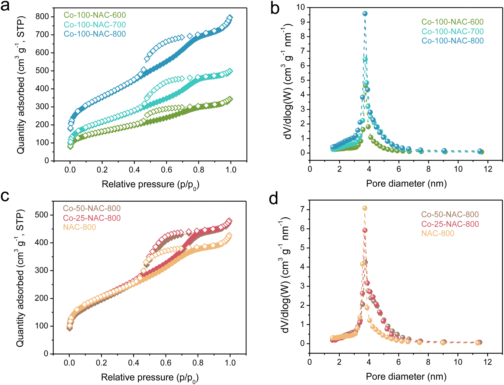 | ||
| Fig. 1 N2-sorption isotherm (a) and (c) and pore-size distribution (b) and (d) of Co-NAC catalysts carbonized at 600, 700, and 800 °C with different metal loadings. The samples are named as “Co-x-NAC-y”, which are prepared with x mg of added Co(acac)2 and under a carbonization temperature of y °C. The actual Co loadings are summarized in Table S1 (ESI†). NAC-800 is a sample prepared using the same method but without addition of a Co precursor. | ||
High-resolution scanning transmission electron microscopy (HR-STEM) study of the representative Co-100-NAC-800 revealed single Co atoms embedded on NAC, with no observable nanoparticles or clusters (Fig. 2(a); Co single atoms are indicated by blue arrows). The uniform distribution of Co on the NAC substrate was confirmed through energy dispersive X-ray spectroscopy (EDS) elemental mapping (Fig. 2(b)–(e)), Indicating the successful preparation of the single-atom Co-NAC catalyst.
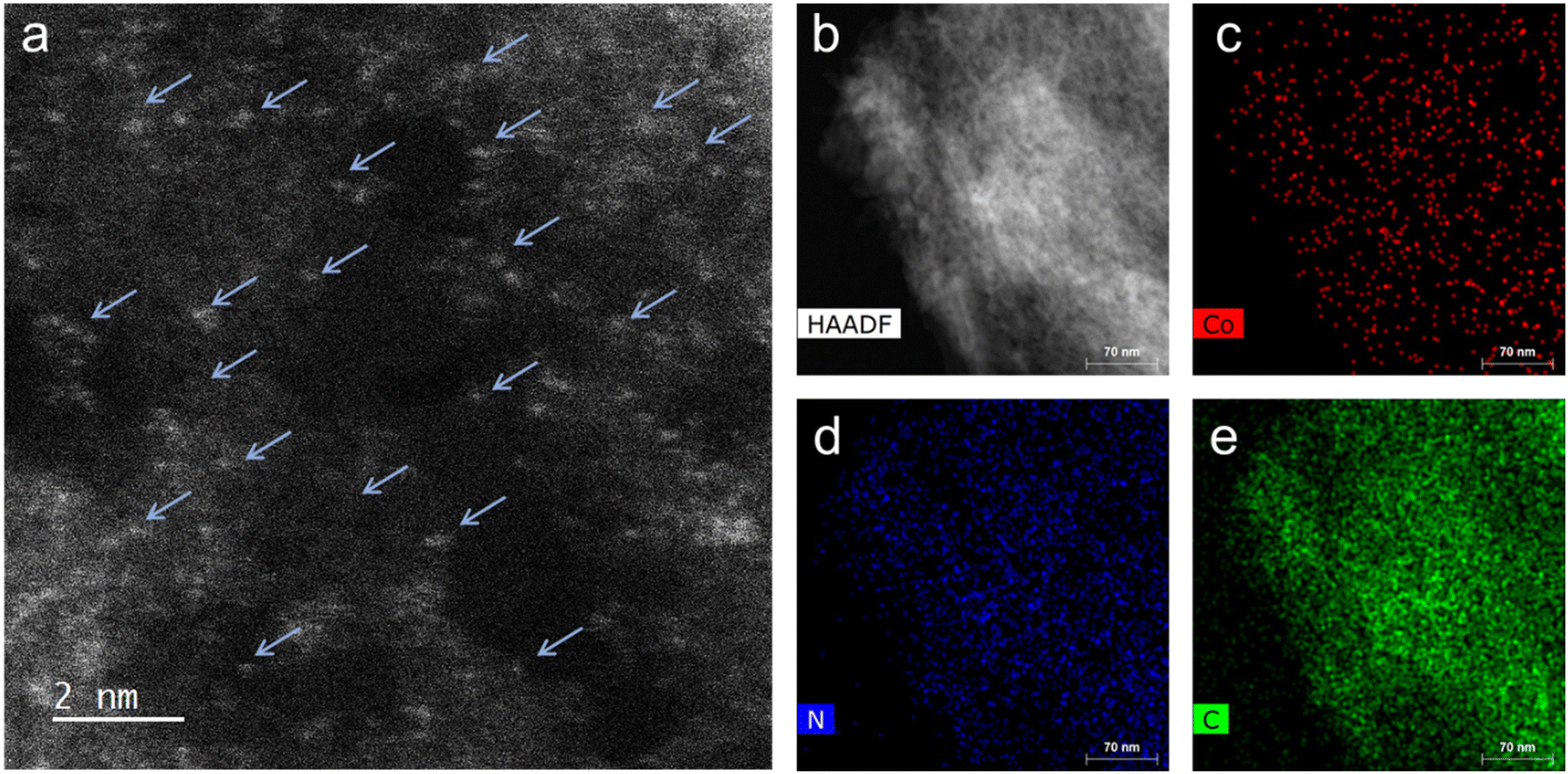 | ||
| Fig. 2 Electron-microscopy characterization of Co-100-NAC-800. (a) HR-STEM image of Co-NAC, the arrows indicate the single-atom Co on the NAC support. (b)–(e) EDS elemental mapping images of Co-NAC: (b) HAADF-STEM image; (c) Co mapping; (d) C mapping; (e) N mapping. | ||
X-ray absorption experiments of the Co K-edge were carried out for representative Co-NAC samples. As shown in Fig. S5a (ESI†), X-ray absorption near-edge structure (XANES) spectra of all three samples present a higher energy pre-edge and a more intense white line than those of Co foil, suggesting oxidized Co species. The XANES spectra of Co-NAC catalysts are consistent with 4-coordinate cobalt atoms reported in the literature.23–25 In the extended X-ray absorption fine structure (EXAFS) spectra, only one main peak was observed for the first shell (Fig. S5b, ESI†). Fittings of the EXAFS spectra with defined coordination numbers of 4 for all samples gave bond lengths of 1.94, 1.94 and 1.99 Å (Fig. S6 and Table S3, ESI†) for Co-NAC-800, Co-NAC-700, and Co-NAC-600, respectively, best assigned as Co–N bonds.26,27 There was no detection of Co–Co at 2.49 Å (after phase correction) in the second shell. Consequently, the results of XANES and EXAFS suggested that cobalt atoms were atomically dispersed and bonded with most likely four nitrogen atoms on the NAC support. X-ray photoelectron spectroscopy (XPS) suggested that the Co species in the Co-NAC were mainly Co2+, while there were several N species, including graphitic, pyrrolic, and pyridinic N, existing in the Co-NAC (Fig. S7, ESI†).
Electrocatalytic HER
Screening of the HER activity over different metal-NACs was carried out under alkaline electrolyte (1 M KOH) in a H-cell. Carbon fiber paper (1 cm2) with single-atom catalyst deposition, Hg/HgO (1 M KOH), and Pt mesh were used as the working, reference, and counter electrodes, respectively. Nafion 117 membrane was used to separate the cathode and anode. LSV was performed from 0 to −0.5 V versus the reverse hydrogen electrode (RHE) to monitor the HER performance of metal-NACs and compared with metal-free NAC-800 support and commercial Pt/Vulcan. Fe-100-NAC-800, Co-100-NAC-800, and Ni-100-NAC-800 showed similar current change behavior with larger overpotential than Pt/Vulcan but rapid current increase, while Cu-NAC and Ru-NAC showed a sluggish HER over the test range (Fig. S8, ESI†). Among these catalysts, Co-100-NAC-800 demonstrated the smallest overpotential, 207 mV at 10 mA cm−2 and 292 mV at 50 mA cm−2. The rapid current increase for Co-NAC permitted a high-current-density HER under relatively small overpotential compared with the single-atom catalysts reported in the literature.12,14,17We further performed HER in a single cell with Co-NAC catalysts to test the effect of different synthetic parameters. The single-cell setup helped to eliminate the cation exchange limitation on the Nafion membrane at a high current density. Synthetic parameters, particularly the carbonization temperature, can directly impact the physiochemical properties of catalysts, including the N content of the NAC support (Table S4, ESI†), local coordination of metal sites, conductivity, and surface area. Besides, the density of catalytically active sites is essential for a high-current HER application. Therefore, Co-NAC catalysts were prepared and examined for the large-current HER with different amounts of Co precursors and carbonization at different temperatures. The exact Co loading was measured using inductively coupled plasma mass spectrometry (ICP-MS) (Table S1, ESI†). From the LSV profile of Co-NACs shown in Fig. 3(a), Co-100-NAC-800 prepared at 800 °C with the highest Co loading showed the smallest overpotential (310 mV) at a current density of 200 mA cm−2. Co-NAC catalysts prepared at lower temperatures had a larger onset overpotential; in contrast, Co-100-NAC-600 showed negligible activity in the HER within the tested potential range. Like Co-100-NAC-800, Co-100-NAC-700 also enabled a rapid current increase but started at a larger overpotential after a considerable window of the sluggish current response. As summarized in Fig. 3(b), the trend of change in the HER overpotential with respect to Co loadings of Co-NAC-800 catalysts aligned with our prediction that catalysts with high Co loading provide more active sites for the HER, improve the overall kinetics, and lower the HER overpotential at a high current density.
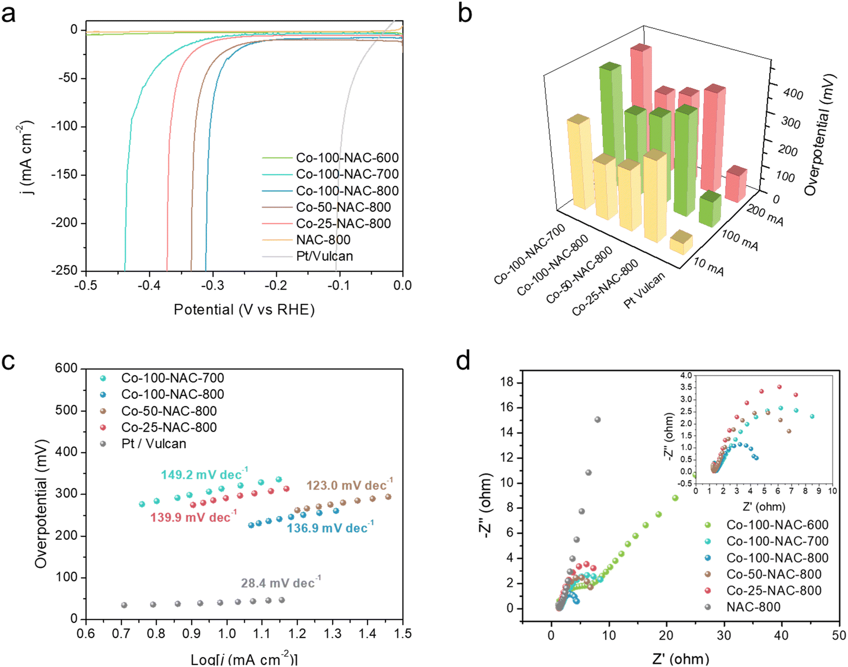 | ||
| Fig. 3 HER evaluation on Co-NAC. (a) LSV; (b) overpotential at 10, 100, and 200 mA cm−2; (c) Tafel plots; (d) Nyquist plots at −0.3 V; insert: zoom-in Nyquist plot. Co-100-NAC-600 overlaps with NAC-800 in (a). | ||
The Tafel plots of Co-NAC catalysts provided insight into the HER mechanism, as shown in Fig. 3(c).28 In the region of low current density, Co-NAC catalysts presented a Tafel plot larger than 120 mV dec−1, indicating the Volmer step to be the rate-determining step.28 It is generally accepted that the good conductivity of electrodes is more desirable in the electrocatalytic process to maximize the efficiency of electron utilization.29 Electrochemical impedance spectroscopy (EIS) was conducted to study the conductivity properties of Co-NACs under an overpotential of 300 mV. As shown from the Nyquist plot in Fig. 3(d), the resistances of the Co-100-NAC-800 were better than Co-100-NAC-600 and Co-100-NAC-700. With better conductivity, the Joule loss of Co-100-NAC-800 at a high current density was smaller than those of Co-100-NAC-600 and Co-100-NAC-700.
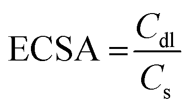
The surface area of the electrode can affect mass transfer, especially under large-current conditions. Large electrode surface areas are therefore pursued to eliminate the limitation of mass transfer. The electrochemical surface areas (ECSA) of Co-NACs were estimated using double-layer capacitance (Cdl), as shown in Fig. S9–S14 (ESI†). Cyclic voltammetry (CV) was performed at different scanning rates in a potential range without any faradaic process. The slope of current density versus scanning rate is the double-layer capacitance of the Co-NAC electrode, and the ECSA can be calculated using the ratio between Cdl and specific capacitance (Cs), as shown in eqn (1). Measuring the Cs of a material involves an unachievable flat electrode with this single-atom porous material. However, researchers have measured a series of materials for their specific capacitance, which typically ranges between 0.022 to 0.130 mF cm−2 in alkaline electrolytes.30,31 In this case, we estimated the ECSA of Co-NAC using Cs = 0.06 mF cm−2. As mentioned above, the NAC support has a large surface area and ordered mesoporous structure; as a result, the corresponding ECSA of NAC catalysts was calculated to be from 531.7 to 2455 cm2 (per cm2 geometric electrode surface). The large ECSA maximizes exposure to active sites and thus minimizes the mass-transfer limitation, which makes the HER at a high current density feasible.
 | (1) |
The durability of electrodes is a crucial parameter for industrial applications. Enhancing durability under a high current density is challenging because the large current could change the structure of the electrode, leading to site deactivation or metal leaching. A 20-h stability test was performed at a current density of 50 mA cm−2 in 1 M KOH electrolyte with stirring. As shown in Fig. 4(a), the potential remained unchanged over the 20-h test with the Co-100-NAC-800 catalyst. At the same time, a hydrogen bubble was continuously generated from the electrode (shown in Fig. S15 and Supplementary Video, ESI†). No structure evolution of Co-100-NAC-800 was observed from the XRD pattern after the 20-h stability test (Fig. S16, ESI†).
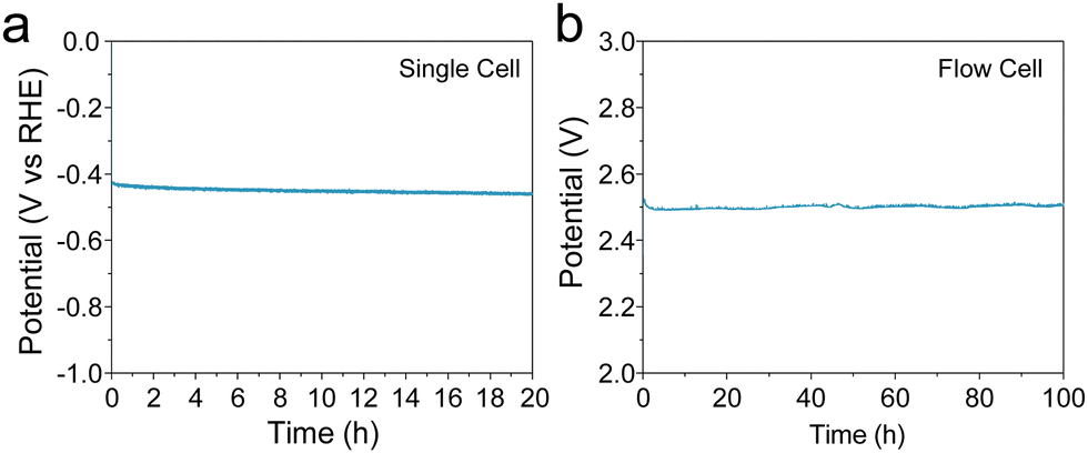 | ||
| Fig. 4 Stability test of Co-100-NAC-800. (a) Chronopotentiometry (CP) plot showing the stability test at 50 mA cm−2; (b) 100-h water-splitting test at 150 mA cm−2 current density in flow cell with Co-100-NAC-800 as the cathode catalyst and Pt on carbon as the anode catalyst. | ||
To evaluate the long-term stability of the Co-NAC under practical conditions, we conducted a continuous flow test. A membrane electrode assembly (MEA) was built with Co-100-NAC-800 as the cathode catalyst and Pt/Vulcan as the anode catalyst to test the stability of the Co-NAC catalyst. As shown in Fig. 4(b), the initial voltage of the water-splitting was 2.50 V at a current density of 150 mA cm−2. Despite the observed overpotential of water-splitting being compromised by the sluggish OER on the Pt electrode, the cell voltage remained stable at 2.50 V during the 100-h stability test with no voltage increase.
Theoretical insights
DFT calculations were performed to provide insights into the atomic structure of the potential active sites for the HER. Gibbs free energy of H adsorption was used as a descriptor for the HER activity, as shown in the literature.32,33Fig. 5 shows that the H binding energy on the CoN4 is 0.18 eV. As indicated in our previous study, the binding configuration between the single metal atom and the substrate atom (nitrogen or carbon) could be altered among the coordination (NxC4−x) of the NAC.22 Thus, DFT calculations were carried out on Co-NAC with these possible coordinations (Fig. 5). To compare their metal–substrate binding configuration, the values with different bond lengths between the Co and N (or C) atoms are provided in Table S5 (ESI†). The shorter metal–support bond and the increased number of N coordinations enabled the CoN4 structure to have a stronger metal–substrate interaction, in agreement with the EXAFS results (Fig. S5 and S6, ESI†). The HER energy profiles of Co-NACs were further investigated for different Co-Nx-NAC structures. The different N coordinations moderated the Co–H binding, with CoN3C1 showing the least difference in free energy for H adsorption on the metal centre, indicating the lowest overpotential based on the computational hydrogen electrode (CHE) model.34 The thermodynamic calculations in Fig. 5 thus suggest that Co-NACs, possibly with the CoN3 site, could also show promising HER activity. Our DFT calculations could not unambiguously determine the exact local binding configuration of Co (e.g., N4vs. N3C1) in Co-NAC, and in the real samples, different metal-coordination likely coexist. Nevertheless, the calculations reveal that single-atom Co with various Co–N coordination displayed favorable hydrogen binding that was close to thermoneutral at the metal centre.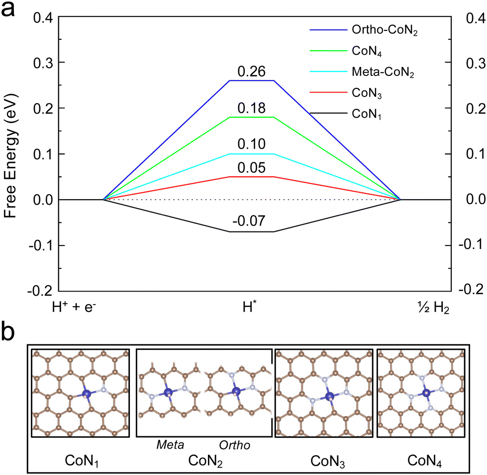 | ||
| Fig. 5 DFT calculations of hydrogen adsorption. (a) Calculated HER free-energy diagram over different configurations of Co-Nx-NAC. The H binding energy is labeled on top of each configuration. (b) Atomic structures of H adsorbed on Co-Nx-NAC. | ||
Conclusions
We systematically studied the single-atom Co materials, Co-NACs, which efficiently catalyzed the HER under a high current density. The synthetic parameters, including Co metal loading and carbonization temperature, were varied as critical parameters for HER-performance studies. High Co loading and a high carbonization temperature led to low overpotential and high current density. On the contrary, a low carbonization temperature resulted in high resistance, which limited the achievable current density in the HER. Both kinetic analysis and theoretical calculations suggested that the Volmer step was the rate-limiting step. The high surface area of the NAC support boosted the HER current by maximizing exposed active species and minimizing mass-transfer limitations. With a combination of high Co loading and large electrode surface area, enhanced kinetics enabled Co-100-NAC-800 to overcome a large HER onset potential and access a high current density (200 mA cm−2) at a moderate overpotential (310 mV) in LSV tests. In addition, Co-NAC-800 demonstrated stability in the HER over 100 h under strong alkaline conditions and at a high current density, making it feasible for scalable industrial applications.Methods
Materials
Iron(III) acetylacetonate (purity ≥99.5%, trace metal), cobalt(II) acetylacetonate (≥99%), nickel(II) acetylacetonate (95%), copper(II) acetylacetonate (≥99.9%, trace metal), Ruthenium(III) acetylacetonate (97%), carbon tetrachloride (≥99.9%), ethylenediamine (≥99.5%), tetraethyl orthosilicate (TEOS, 98%), and pluronic P123 (Mn ∼ 5800) were purchased from MilliporeSigma. Hydrofluoric acid (trace metal), hydrochloric acid (trace metal), and nitric acid (trace metal) were purchased from Thermo Fisher. All chemicals were used as received.Synthesis of transition metal single-atom on NAC
Characterization
Powder X-ray diffraction (XRD) was performed using a Bruker D8A25 diffractometer with Cu Kα radiation (λ = 1.54184 Å). N2 physisorption was performed using an auto-adsorption analyzer (3Flex; Micromeritics) at −196 °C. Inductively coupled plasma mass spectroscopy (ICP-MS) for metal loadings was measured with a spectrometer (X Series 2; Thermo Scientific). HAADF-STEM imaging was performed on a Titan Themis 300 equipped with a gun monochromator and probe spherical aberration (Cs) corrector operated at 200 kV. EDS mapping data were collected with a Super-X EDX detector. CHNS analysis was conducted using an Elemetar Unicube Analyzer. X-ray adsorption spectroscopy (XAS) experiments, including X-ray absorption near edge structure (XANES) and extended X-ray absorption fine structure (EXAFS), were conducted at 7-BM QAS beamline in National Synchrotron Light Source II at Brookhaven National Laboratory. The Co K-edge of Co-NAC samples was collected in fluorescence mode at room temperature and ambient pressure. Co foil was also collected to act as a reference for energy calibration and drift correction of the monochromator.“Athena” and “Artemis” from the Demeter software package were used to analyze the data of each sample.36,37 The FEFF program was used for the calculation and appropriate fitting of EXAFS spectra. A k range between 2.5 to 8.5 Å−1 was used for Fourier-transformed (FT) EXAFS spectra.
HER
| ERHE = EHg/HgO + E0Hg/HgO + 0.059pH | (2) |
![[thin space (1/6-em)]](https://www.rsc.org/images/entities/char_2009.gif) :1. The catholyte and anolyte of 1 M KOH were circulated by a peristaltic pump (Masterflex® L/S®) at 20 mL min−1. The applied current was controlled by a SP-300 potentiostat/galvanostat (biologic). The membrane used to separate the catholyte and anolyte was an anion exchange membrane (A201; Tokuyama). The test was performed at room temperature.
:1. The catholyte and anolyte of 1 M KOH were circulated by a peristaltic pump (Masterflex® L/S®) at 20 mL min−1. The applied current was controlled by a SP-300 potentiostat/galvanostat (biologic). The membrane used to separate the catholyte and anolyte was an anion exchange membrane (A201; Tokuyama). The test was performed at room temperature.
Computational details
DFT calculations were performed using the VASP package.38 The Perdew–Burke–Ernzerhof (PBE) functional within the generalized gradient approximation (GGA) was used for the exchange–correlation energy.39 The electron–ion interaction was described by the projector augmented wave (PAW) approach.40,41 The van der Waals interaction was included using the DFT-D3 method.42 All electronic energies were converged to 10−5 eV, and the atomic force on each atom was minimized to be <0.02 eV Å−1. The structures of single-atom NACs were taken from a previous work.22 A (3 × 3 × 1) Monkhorst–Pack k-point was used to sample the first Brillouin zone. The Gibbs free energy of adsorption was computed using the computational hydrogen electrode model where the chemical potential of (H+ + e−) at pH = 0 equalled the chemical potential of 1-bar H2 in the gas phase at 298 K.32,34 We added 0.24 eV onto the DFT-calculated total energies to take into account the entropy lost and zero-point energy change for the adsorbed state.32Author contributions
All authors contributed to the conceptualization of this study. JY conducted the electrochemical evaluation and part of the materials characterization under the supervision of WH. YY performed the theoretical study under the supervision of BW. YL synthesized the materials and conducted part of the characterization under the supervision of ZZ, LQ, and WH. HL assisted with electrochemical tests under the supervision of WL. SS assisted with the electrochemical tests under the supervision of WH. YL, SX, and FL conducted the XAS study. JSO and LZ conducted the HR-STEM characterization of catalysts. JY and YY drafted the manuscript under the supervision of BW and WH. YL and LQ drafted the XAS part of the manuscript. All authors contributed to the revision and finalization of this manuscript.Data availability
All data are available in the main text and the ESI.†Conflicts of interest
There are no conflicts to declare.Acknowledgements
This work was partially supported by NSF grant CHE-2108306/2108307 and the Trapp award from Iowa State University. L. Q. and Y. L. were supported by the U.S. Department of Energy (DOE), Office of Basic Energy Sciences, Division of Chemical Sciences, Geosciences, and Biosciences, Catalysis Science program. The Ames Laboratory is operated for the U.S. DOE by Iowa State University under contract number DE-AC02-07CH11358. Z. Z. was supported by NSFC grant 22078288. Y. L. was supported by the International Doctoral Exchange Fellowship Program of Zhejiang University. Computations were performed at the OU Supercomputing Center for Education & Research and the National Energy Research Scientific Computing Center (NERSC), a U.S. DOE of Science User Facility, and were supported by the U.S. DOE, Basic Energy Sciences (DE-SC0018284). This research study used beamline 7-BM (QAS) of the National Synchrotron Light Source II, a U.S. DOE Office of Science User Facility operated for the DOE Office of Science by Brookhaven National Laboratory under contract number DE-SC0012704. All electron microscopy and related work were performed using instruments in the Sensitive Instrument Facility in Ames National Laboratory.References
- M. Zeng and Y. Li, J. Mater. Chem. A, 2015, 3, 14942–14962 RSC.
- Z. Zhao, H. Liu, W. Gao, W. Xue, Z. Liu, J. Huang, X. Pan and Y. Huang, J. Am. Chem. Soc., 2018, 140, 9046–9050 CrossRef CAS PubMed.
- F. Y. Yu, Z. L. Lang, L. Y. Yin, K. Feng, Y. J. Xia, H. Q. Tan, H. T. Zhu, J. Zhong, Z. H. Kang and Y. G. Li, Nat. Commun., 2020, 11, 490 CrossRef.
- L. Zhang, H. Liu, S. Liu, M. Norouzi Banis, Z. Song, J. Li, L. Yang, M. Markiewicz, Y. Zhao, R. Li, M. Zheng, S. Ye, Z.-J. Zhao, G. A. Botton and X. Sun, ACS Catal., 2019, 9, 9350–9358 CrossRef CAS.
- T. He, W. Wang, F. Shi, X. Yang, X. Li, J. Wu, Y. Yin and M. Jin, Nature, 2021, 598, 76–81 CrossRef CAS PubMed.
- Z. Shi, X. Zhang, X. Lin, G. Liu, C. Ling, S. Xi, B. Chen, Y. Ge, C. Tan, Z. Lai, Z. Huang, X. Ruan, L. Zhai, L. Li, Z. Li, X. Wang, G.-H. Nam, J. Liu, Q. He, Z. Guan, J. Wang, C.-S. Lee, A. R. J. Kucernak and H. Zhang, Nature, 2023, 621, 300–305 CrossRef CAS PubMed.
- L. Liao, S. Wang, J. Xiao, X. Bian, Y. Zhang, M. D. Scanlon, X. Hu, Y. Tang, B. Liu and H. H. Girault, Energy Environ. Sci., 2014, 7, 387–392 RSC.
- H. Wang, N. Ma, Y. Cao, H. Yu, J. Zuo, W. Fan and F. Peng, Int. J. Hydrogen Energy, 2019, 44, 3649–3657 CrossRef CAS.
- H. Wang, X. Xiao, S. Liu, C. L. Chiang, X. Kuai, C. K. Peng, Y. C. Lin, X. Meng, J. Zhao, J. Choi, Y. G. Lin, J. M. Lee and L. Gao, J. Am. Chem. Soc., 2019, 141, 18578–18584 CrossRef CAS PubMed.
- X. Li, R. Zhang, Y. Luo, Q. Liu, S. Lu, G. Chen, S. Gao, S. Chen and X. Sun, Sustainable Energy Fuels, 2020, 4, 3884–3887 RSC.
- T.-X. Huang, X. Cong, S.-S. Wu, J.-B. Wu, Y.-F. Bao, M.-F. Cao, L. Wu, M.-L. Lin, X. Wang, P.-H. Tan and B. Ren, Nat. Catal., 2024, 7, 646–654 CrossRef CAS.
- Q. Zhang and J. Guan, Adv. Funct. Mater., 2020, 2000768, DOI:10.1002/adfm.202000768.
- Q. Yang, H. Liu, P. Yuan, Y. Jia, L. Zhuang, H. Zhang, X. Yan, G. Liu, Y. Zhao, J. Liu, S. Wei, L. Song, Q. Wu, B. Ge, L. Zhang, K. Wang, X. Wang, C.-R. Chang and X. Yao, J. Am. Chem. Soc., 2022, 144, 2171–2178 CrossRef CAS.
- R. Liu, Z. Gong, J. Liu, J. Dong, J. Liao, H. Liu, H. Huang, J. Liu, M. Yan, K. Huang, H. Gong, J. Zhu, C. Cui, G. Ye and H. Fei, Adv. Mater., 2021, 33, e2103533 CrossRef.
- T. Sun, S. Zhao, W. Chen, D. Zhai, J. Dong, Y. Wang, S. Zhang, A. Han, L. Gu, R. Yu, X. Wen, H. Ren, L. Xu, C. Chen, Q. Peng, D. Wang and Y. Li, Proc. Natl. Acad. Sci. U. S. A., 2018, 115, 12692–12697 CrossRef CAS.
- J. Li, H. Li, W. Xie, S. Li, Y. Song, K. Fan, J. Y. Lee and M. Shao, Small Methods, 2022, 6, e2101324 CrossRef.
- X. Liu, Y. Deng, L. Zheng, M. R. Kesama, C. Tang and Y. Zhu, ACS Catal., 2022, 5517–5526, DOI:10.1021/acscatal.2c01253.
- X. Wan, X. Liu, Y. Li, R. Yu, L. Zheng, W. Yan, H. Wang, M. Xu and J. Shui, Nat. Catal., 2019, 2, 259–268 CrossRef CAS.
- D. Lyu, Y. Du, S. Huang, B. Y. Mollamahale, X. Zhang, S. W. Hasan, F. Yu, S. Wang, Z. Q. Tian and P. K. Shen, ACS Appl. Mater. Interfaces, 2019, 11, 39809–39819 CrossRef CAS.
- Z. Yin, J. Yu, Z. Xie, S.-W. Yu, L. Zhang, T. Akauola, J. G. Chen, W. Huang, L. Qi and S. Zhang, J. Am. Chem. Soc., 2022, 144, 20931–20938 CrossRef CAS.
- Y. Lin, R. Nie, Y. Li, X. Wu, J. Yu, S. Xie, Y. Shen, S. Mao, Y. Chen, D. Lu, Z. Bao, Q. Yang, Q. Ren, Y. Yang, F. Liu, L. Qi, W. Huang and Z. Zhang, Nano Res., 2022, 15, 10006–10013 CrossRef CAS.
- Z. Luo, Z. Yin, J. Yu, Y. Yan, B. Hu, R. Nie, A. F. Kolln, X. Wu, R. K. Behera, M. Chen, L. Zhou, F. Liu, B. Wang, W. Huang, S. Zhang and L. Qi, Small, 2022, 18, 2107799 CrossRef CAS.
- T. Jiang and D. E. Ellis, J. Mater. Res., 1996, 11, 2242–2256 CrossRef CAS.
- G. Jacobs, Y. Ji, B. H. Davis, D. Cronauer, A. J. Kropf and C. L. Marshall, Appl. Catal., A, 2007, 333, 177–191 CrossRef CAS.
- M. Hunault, G. Calas, L. Galoisy, G. Lelong and M. Newville, J. Am. Ceram. Soc., 2014, 97, 60–62 CrossRef CAS.
- C. Zhu, Q. Shi, B. Z. Xu, S. Fu, G. Wan, C. Yang, S. Yao, J. Song, H. Zhou, D. Du, S. P. Beckman, D. Su and Y. Lin, Adv. Energy Mater., 2018, 8, 1801956 CrossRef.
- Z.-L. Wang, X.-F. Hao, Z. Jiang, X.-P. Sun, D. Xu, J. Wang, H.-X. Zhong, F.-L. Meng and X.-B. Zhang, J. Am. Chem. Soc., 2015, 137, 15070–15073 CrossRef CAS.
- T. Shinagawa, A. T. Garcia-Esparza and K. Takanabe, Sci. Rep., 2015, 5, 13801 CrossRef.
- Y. Xue, B. Huang, Y. Yi, Y. Guo, Z. Zuo, Y. Li, Z. Jia, H. Liu and Y. Li, Nat. Commun., 2018, 9, 1460 CrossRef PubMed.
- C. C. L. McCrory, S. Jung, J. C. Peters and T. F. Jaramillo, J. Am. Chem. Soc., 2013, 135, 16977–16987 CrossRef CAS PubMed.
- D. Qu and H. Shi, J. Power Sources, 1998, 74, 99–107 CrossRef CAS.
- J. K. Nørskov, T. Bligaard, A. Logadottir, J. R. Kitchin, J. G. Chen, S. Pandelov and U. Stimming, J. Electrochem. Soc., 2005, 152, J23 CrossRef.
- V. Fung, G. Hu, Z. Wu and D.-E. Jiang, J. Phys. Chem. C, 2020, 124, 19571–19578 CrossRef CAS.
- J. K. Nørskov, J. Rossmeisl, A. Logadottir, L. Lindqvist, J. R. Kitchin, T. Bligaard and H. Jónsson, J. Phys. Chem. B, 2004, 108, 17886–17892 CrossRef.
- D. Zhao, J. Feng, Q. Huo, N. Melosh, G. H. Fredrickson, B. F. Chmelka and G. D. Stucky, Science, 1998, 279, 548–552 CrossRef CAS PubMed.
- D. Bazin and L. Guczi, Appl. Catal., A, 2001, 213, 147–162 CrossRef CAS.
- B. Ravel and M. Newville, J. Synchrotron Rad., 2005, 12, 537–541 CrossRef CAS PubMed.
- G. Kresse and J. Hafner, Phys. Rev. B: Condens. Matter Mater. Phys., 1993, 47, 558–561 CrossRef CAS.
- J. P. Perdew, K. Burke and M. Ernzerhof, Phys. Rev. Lett., 1996, 77, 3865–3868 CrossRef CAS PubMed.
- P. E. Blöchl, Phys. Rev. B: Condens. Matter Mater. Phys., 1994, 50, 17953–17979 CrossRef.
- G. Kresse and D. Joubert, Phys. Rev. B: Condens. Matter Mater. Phys., 1999, 59, 1758–1775 CrossRef CAS.
- S. Grimme, J. Antony, S. Ehrlich and H. Krieg, J. Chem. Phys., 2010, 132, 154104 CrossRef.
Footnotes |
| † Electronic supplementary information (ESI) available. See DOI: https://doi.org/10.1039/d4nh00299g |
| ‡ These authors contributed equally to this work. |
| This journal is © The Royal Society of Chemistry 2024 |