
Incorporation of green synthesized ZnO with the support of rGO sheets into PVDF membranes to improve their filtration and antifouling properties for wastewater treatment
Ankush
Agrawal
 a,
Nishel
Saini
b,
Kamlendra
Awasthi
b and
Anjali
Awasthi
*a
a,
Nishel
Saini
b,
Kamlendra
Awasthi
b and
Anjali
Awasthi
*a
aDepartment of Zoology, University of Rajasthan, Jaipur 302004, India. E-mail: anjkam.awasthi@gmail.com
bDepartment of Physics, Malaviya National Institute of Technology Jaipur, Jaipur 302017, India
First published on 16th September 2024
Abstract
The growing scarcity of clean water necessitates urgent interventions in wastewater treatment. Polymeric membranes are prevalent in this domain. However, due to their hydrophobic behaviour, they become more prone to fouling. To address this issue, we synthesized hydrophilic nanomaterials as additives to prepare polymer nanocomposite membranes with enhanced hydrophilicity. The eco-friendly zinc oxide (ZnO) nanomaterial was synthesized via a green route, and reduced graphene oxide (rGO) and a rGO/ZnO composite were synthesized using a chemical process and characterized using FESEM, FTIR, XRD, and zeta potential techniques. The synthesized nanomaterials were incorporated into PVDF membranes, and the prepared membranes were characterized using FESEM with EDX, FTIR, and contact angle measurements, along with mechanical strength determination. The filtration properties of the membranes were evaluated using a dead-end filtration module. The FESEM images revealed the finger-like structure in the membranes, which increases with the incorporation of nanomaterials. The results demonstrated that among all the membranes, the rGO/ZnO-PVDF showed the highest membrane permeability due to increased membrane porosity, pore size, and finger-like macrovoid sponge structures. The rejection of BSA protein and CBB dye increased due to the negative charge provided by the ZnO in the rGO/ZnO nanocomposite. The antifouling study reveals that the rGO/ZnO-PVDF membrane had the highest FRR value of ∼50.05% among the various synthesized membranes. The disk diffusion data of the synthesized nanomaterials and nanocomposite membranes confirms their antibacterial activity and suggests that the addition of rGO/ZnO nanomaterial can provide anti-biofouling behaviour to the polymer membranes by minimizing the adhesion of bacteria on the surface of the membrane. The results showed that the rGO/ZnO-PVDF membrane possesses antifouling and anti-biofouling behaviour, useful for minimising the pollutants from wastewater.
1. Introduction
At the present time, the rapid growth of the population is causing inadequate quality and quantity of water supply all over the world.1 The anthropogenic activities generate wastes such as industrial wastes, residential wastes, and agricultural wastes, which contain higher levels of liquid wastes that are disposed of directly into water bodies.2 As a result, the primary challenge becomes to treat the harmful wastewater generated by the increasing population and industrialization. Wastewater treatment is a way of cleaning and enhancing water quality by removing any impurities or toxins before reusing or discharging them into the environment.3Membrane technology has gained popularity in recent times for purifying water, desalination, wastewater processing, re-use, and regeneration. Polymer membranes are frequently used in wastewater treatment because of their ease of use, selective segregation, excellent productivity, high efficacy of removal, and the absence of toxic by-products.4,5 Polymeric membranes offer excellent versatility, flexibility, high film-forming capabilities, physical durability, and stable chemical properties, which makes them especially effective for wastewater treatment.6 Polymeric membranes can be made with a variety of polymers, including polyvinylidene fluoride (PVDF), polyvinyl chloride (PVC), polyvinyl alcohol (PVA), polyether sulfone (PES), cellulose acetate (CA), polyamide (PA), chitosan, and others.2 Among these membranes, pressure serves as a typical operating factor for membrane separation.7 PVDF polymer is widely used for the synthesis of membranes for wastewater treatment due to its several advantages, including easy wetting, and strong chemical resistivity with great mechanical and thermal properties, which are crucial for membrane applications, especially in harsh environments.8 PVDF also provides ease of processing, and well-established fabrication techniques, making it an ideal choice for developing advanced filtration membranes.9 However, the characteristic hydrophobic and poor surface features of the PVDF polymer cause membrane fouling, which reduces water permeability and membrane life while raising operational costs.10 As a result, it is required to modify the membranes through various strategies such as functionalization, incorporation of nanomaterials, etc. for increased permeability and selectivity, as well as strong antifouling qualities. Engineering of nanochannels in polymer membranes can become an advanced filtration technology for the removal of persistent pollutants from wastewater.11
The usage of various nanomaterials on spacers or their incorporation into membranes has proved to be an efficient strategy. Spacers provide the advantages of easy modification and simpler performance but lack structural integrity and long-term stability.12–14 Inorganic nanoparticles, which include metal/metal oxide and carbon-based nanomaterials, can be distributed in a polymeric membrane matrix to form nanocomposite membranes due to their hydrophilicity, larger surface area, proper pore channels, and other antifouling features.15 Nanoparticles such as ZnO,16,17 SiO2,18 CuO,19 ZrO2,20 TiO2,21 Fe3O4,22 Ag,23–25 zeolite,26,27 GO,28,29 and carbon nanotubes30 are recommended for modifying polymer membranes. Among these, zinc oxide (ZnO) nanomaterials have great potential because of their low cost, higher surface area, catalytic behaviour, and wide band gap. The ZnO nanoparticles (NPs) have a strong affinity for water so they are used as additives into polymer membranes to increase membrane hydrophilicity.31 ZnO NPs can also act as a crosslinking agent, increasing the membrane's mechanical strength. Balta et al.32 and Shen et al.33 discovered that the addition of ZnO NPs into the PES membrane matrix improved membrane properties and reduced fouling. The addition of ZnO NPs into PVDF polymer matrices yields strong self-cleaning and antifouling properties.34 Zhao et al.35 reported that the integration of ZnO NPs into the PVDF polymer considerably enhanced the Bovine serum albumin (BSA) protein rejection and membrane mechanical properties. Furthermore, ZnO NPs have antimicrobial activity against different microorganisms, and they can provide antibiofouling behaviour to polymer membranes.16,36 The chemical and physical production of ZnO NPs is often expensive and hazardous to human health & the environment. Furthermore, the antimicrobial nanoparticles should be environmentally friendly and low in toxicity. For this, ZnO is synthesized via a green route using various plant extracts to produce eco-friendly and cost-effective materials.37–39
Graphene oxide (GO) has recently seen widespread usage in membrane filtration due to its distinctive 2D structure with strong chemical durability and better physical qualities.40,41 GO nanosheets have a propensity to agglomerate in the polymer matrices due to π–π stacking, which restricts their employment in membrane construction and causes instability in the dope solution. The functionalization of GO sheets can be a significant solution to this problem.42 ZnO is the most common metal oxide used for GO functionalization because of its valuable properties such as cost-effectiveness, low toxicity, ecological compatibility, thermal and mechanical stability, higher surface area and antimicrobial features.16,28,43 The hybrid inorganic nanoparticle composite membrane demonstrated increased water flow, hydrophilicity, mechanical strength, rejection, and high surface area. Kusworo et al. introduced the GO and ZnO NPs into polysulfone (PSf) membranes using the phase inversion method to increase the hydrophilicity and antifouling properties of the membrane for petroleum refinery wastewater treatment.44 They found that mixing 2% GO and 2% ZnO NPs into the PSf membrane increases surface shape, porosity, chemical structure, and mechanical strength, resulting in considerable hydrophilicity and antifouling ability. Kazemi et al. synthesized GO, and GO–ZnO NPs and added them into the matrices of a PVC membrane to increase antifouling properties.42 The FESEM images showed that the alteration of GO with ZnO decreases its agglomeration into PVC polymer matrices. The findings demonstrated that PVC/GO–ZnO membranes showed lesser flux reduction and greater turbidity removal capacity than pure PVC and PVC/GO membranes.
The GO sheets are synthesized by the common Hummers’ method. An addition of the exfoliation step, which is done under alkaline conditions, is the deoxygenation of GO into reduced graphene oxide (rGO), which is a less toxic form of graphene.45,46 The reduction of GO into rGO results in partial repair of the graphene network, which promotes an improvement in membrane conductivity.47 The incorporation of ZnO into rGO gives dual functionality to the polymer membrane by providing both antifouling and antibacterial properties.48 Zhang et al. synthesized a dual functional rGO/ZnO–PES membrane followed by surface grafting of a low-fouling polyampholyte hydrogel (rGO/ZnO–z-PES).48 The results demonstrated that the synthesised membrane exhibited strong, stable, and safe antifouling and anti-biofouling performance, indicating a high potential for wastewater treatment. Kusworo et al. studied the effect of low loadings of ZnO, rGO, and their combination into PES nanohybrid membranes. The SEM results exhibited that the addition of rGO reduces the agglomeration of nanomaterials.49 The membrane morphology, hydrophilicity, and mechanical strength have all improved significantly when using the dual filler rGO/ZnO. In addition, the customized membranes performed better than the plain PES membrane in terms of separation.
In this study, we synthesized an eco-friendly ZnO nanomaterial via a green route using Saraca asoca plant leaves. The use of plant extract for the synthesis of ZnO nanomaterials by considering greener compounds and the use of less hazardous material approach matches the 12 green principles proposed by Szekely.50 Furthermore, less waste generation and the lower cost of membranes with high performances and scalable design make it more advanced towards wastewater treatment. GO sheets were synthesized using the modified hummers method then converted into rGO. The combination of both ZnO and rGO was prepared by an ex situ synthesis method. The synthesized nanomaterials were characterized, and their antibacterial activity was studied using the disk diffusion method. These synthesized nanomaterials are added to the PVDF polymer matrix to enhance their hydrophilicity and membrane performance. These produced membranes were examined for fundamental membrane properties such as shape, structure, mechanical power, water flux, and hydrophilicity, including antibacterial analysis. Also, the rejection and antifouling performance of the fabricated membranes were evaluated using BSA protein and CBB dye.
2. Experimental
2.1 Materials
Saraca asoca (RUBL 21255) plant leaves were collected from Jaipur district, Rajasthan (India). Zinc nitrate hexahydrate (N2O6Zn·6H2O AR, 98%, crystal, MW – 297.49 g mol−1, CAS-no. 10196-18-6, purchased from Merck) and sodium hydroxide (NaOH, 99%, pellets, MW – 40 g mol−1, CAS-no. 1310-73-2, purchased from Merck) were used for the synthesis of ZnO. For the synthesis of GO and rGO, graphite powder (C, 99.5%, black powder, MW – 12.01 g mol−1, CAS-no. 7782-42-5, purchased from CDH), potassium permanganate (KMnO4, ≥99%, MW – 158.03 g mol−1, CAS-no. 7722-64-7, purchased from Merck), hydrogen peroxide (H2O2, ≥30%, solution, MW – 34.01 g mol−1, CAS-no. 7722-84-1, purchased from Merck), hydrogen chloride (HCl, 37%, solution, MW – 36.46 g mol−1, CAS-no. 7647-01-0, purchased from Merck), and L-ascorbic acid (C6H8O6, ≥99%, MW – 176.12 g mol−1, CAS-no. 50-81-7, purchased from Himedia) were used. The polymer membranes were synthesised using PVDF (poly(vinylidene fluoride)) powder ((–CH2CF2–)n, white powder, MP – 155–160 °C, CAS-no. 24937-79-9, purchased from Alfa Aesar) and 1-methyl-2-pyrrolidone (NMP) (C5H9NO, ≥99%, MW – 99.13 g mol−1, CAS-no. 872-50-4, purchased from Thermo Scientific). The membrane fouling and rejection properties were evaluated using bovine serum albumin (BSA) protein (MW – 66.5 kDa, CAS no. 9048-46-8, purchased from Himedia) and Coomassie brilliant blue (CBB) G-250 dye (C47H48N3O7S2Na, MW – 854.01 g mol−1, CAS-no. 6104-58-1, purchased from aMRESCO). All chemicals were commercially sourced at analytical grade and used without further purification.2.2 Synthesis of zinc oxide nanomaterial
The zinc oxide (ZnO) nanomaterial was produced using a leaf extract from the Saraca asoca plant.38,51 For this, 10 g of dried plant leaf powder was stirred with 100 mL of DI water at 80 °C for 2 hours; it was then cooled to room temperature and filtered out. In a beaker, 20 mL of zinc nitrate hexahydrate solution (0.002 M) was prepared, and 10 mL of plant extract was added into the aforesaid solution with constant stirring. Following that, 0.002 M sodium hydroxide (NaOH) solution was added dropwise until the pH reached 12 and then stirred for 2 hours. The presence of a yellowish colloidal solution confirms the synthesis of ZnO nanoparticles. The solution was centrifuged, rinsed, and dried at 80 °C overnight.2.3 Synthesis of reduced graphene oxide nanosheets
Reduced graphene oxide (rGO) sheets were obtained from the reduction of graphene oxide (GO). For this purpose, the graphite powder was converted into graphene oxide using the modified Hummers’ method. First, 45 mL H2SO4 was taken in a beaker, kept in an ice bath, and stirred for around 10 min. To this beaker, 2 g graphite powder was added and mixed for 2 hours on a stirrer, with slow addition of 2 g potassium permanganate (KMnO4). The ice bath was then removed, and the solution was kept on the stirrer for another 2 hours at 35 °C. Then, 90 mL DI was added drop by drop to the mixture and left stirring another 30 min. After this, 10 mL of hydrogen peroxide was added gently to eliminate excess KMnO4 present, which was then followed by the addition of 150 mL DI dropwise. The solution was centrifuged at 10![[thin space (1/6-em)]](https://www.rsc.org/images/entities/char_2009.gif) 000 rpm for 5 min, and the obtained residual was washed with 5% HCl in DI solution, followed by DI washing to obtain a pH value of 7. Then, the obtained GO was washed using DI water and dried in an oven at 90 °C to produce GO powder.
000 rpm for 5 min, and the obtained residual was washed with 5% HCl in DI solution, followed by DI washing to obtain a pH value of 7. Then, the obtained GO was washed using DI water and dried in an oven at 90 °C to produce GO powder.
The obtained GO powder was converted into rGO by using L-ascorbic acid as a reducing agent.52 For this purpose, GO powder was mixed with 0.5 M L-ascorbic acid solution in DI and heated for 1 hour at 95 °C temperature, followed by sonication for 15 min. After the reaction, the resultant black precipitate was filtered through micropore filters and further washed using 1 M HCl solution and DI water to obtain a pH value of 7. The final product is then kept for drying overnight to produce a black-colored powder of rGO.
2.4 Synthesis of the rGO/ZnO nanocomposite
The rGO/ZnO nanocomposites were synthesized using the procedure reported by Boopathy et al.53 For this purpose, 100 mg of synthesized ZnO nanomaterial was mixed into 30 mL of methanol and kept in an ultrasonicater for 50 minutes. Then, 100 mg of synthesized rGO sheets were added to the aforementioned solution and again sonicated for another 50 minutes. Methanol is a polar solvent, which can partially wet both ZnO and rGO surfaces, which might help in achieving better adhesion. Then, the solution was centrifuged and dried at 80 °C overnight.2.5 Fabrication of bare and nanocomposite PVDF membranes
Initially, the PVDF polymer was kept in the oven at 80 °C overnight to eliminate humidity before preparing dope solutions. All types of PVDF membrane, including bare and nanocomposites, were fabricated using the phase inversion method at the composition described in Table 1. The filler nanomaterials were well-dispersed within the PVDF polymer matrix through ultrasonication and stirring methods, which aided in breaking down agglomerates and promoting uniform distribution, enhancing the interfacial contact between the materials.| Membrane | PVDF (wt%) | Nanomaterials (wt%) | |||
|---|---|---|---|---|---|
| ZnO | rGO | RGO/ZnO | NMP (wt%) | ||
| 1. | 18 | — | — | — | 82 |
| 2. | 18 | 0.5 | — | — | 81.5 |
| 3. | 18 | — | 0.5 | — | 81.5 |
| 4. | 18 | — | — | 0.5 | 81.5 |
In brief, for the preparation of pure PVDF membrane, 18 wt% PVDF powder was gradually mixed into the NMP solvent and constantly stirred at 300 rpm for 12 h. For the nanocomposite dope solution preparation, 0.5 wt% of rGO, ZnO, and rGO/ZnO nanomaterial were added to the NMP solvent and ultrasonicated for 20 min. Then, 18 wt% PVDF powder was gradually mixed into the above solution and again stirred for an additional 12 h. After stirring, the prepared dope solution was vacuumed for 3 h to eliminate air bubbles.
To cast membranes, the prepared homogeneous dope solution was poured at the edge of the glass plate and cast using a homemade casting knife with a thickness of approximately 350 μm. Then, membranes were allowed to evaporate in the air for about 30 seconds to produce a thin layer.53 Finally, glass plates were submerged in a coagulation water bath to promote the generation of a high flux membrane by increasing the solvent to non-solvent exchange rate.54
2.6 Characterization of nanomaterials and membranes
The hydrophobic and hydrophilic features of the synthesized membranes were determined by measuring their contact angles with DI water. The contact angle was measured at room temperature using the sessile drop method. For this, the membranes were dried overnight at 60 °C temperature, and then a 10 μL drop of DI water was put on the membrane surface using a microliter syringe. The contact angle value was determined using contact angle meters (Acam-NSC).
The mechanical strength of the pure and nanocomposite membranes was evaluated by measuring their tensile strength. The membrane samples were cut into rectangular pieces 1 cm wide and 5 cm long and fixed on the stage. Then, tensile strength measurements were recorded at an extension rate of 1.0 mm min−1 at ambient temperature using a universal testing machine (UTM Instron-5967).
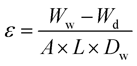
The porosity of the membranes was calculated using the gravimetric method.55 The membrane porosity, denoted as ε (%), is the percentage of pores to total membrane volume. The porosity was calculated by the following equation
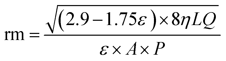
The Guerout–Elford Ferry equation was used to calculate membrane pore size as mean pore radius (rm).56 The equation is
2.7 Antibacterial analysis of nanomaterials
The disk diffusion method was used for assessing the antibacterial properties of the fabricated nanomaterials against Bacillus subtilis (MTCC 121).37,57,58 Bacillus species are known for their biofilm-producing behaviour and contribute to biofouling in both marine and industrial water systems. The overnight-grown bacterial culture was prepared and diluted (1:100) to use as an inoculum. On the other hand, 10 mg mL−1 concentrations of ZnO, rGO, and rGO/ZnO were prepared, and 20 μL of each was placed onto UV-sterilized Whatman filter paper disks (diameter 6 mm). After the spreading of the inoculum on agar plates, nanomaterial-loaded disks were put on agar plates alongside a blank disk (water-loaded) and an antibiotic-loaded disk (gentamicin). The agar plates were placed into an incubator overnight at 37 °C temperature, and then the zone of inhibition was measured to assess the antibacterial activity of the synthesized nanomaterials.
2.8 Membrane filtration properties
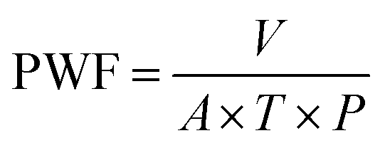
where PWF denotes the pure water flux (L m−2 h−1 bar−1), V indicates the volume of water (L), A stands for an actual membrane area (19.64 m2), T is the filtration time (h), and P represents the pressure in bar.
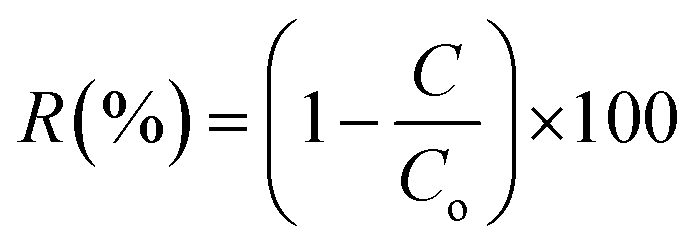
where R is denoted as rejection (%), and C and Co are the concentration of solute in the filtrate and feed solutions (mg L−1), respectively.
2.9 Antifouling properties of the membranes
The flux recovery ratio (FRR) is a renowned metric for assessing membrane antifouling performance. Right after the completion of the pure water filtration, Pwf1 (L m−2 h−1 bar−1) was recorded, and a 500 mg L−1 concentration of BSA solution was substituted with the previous feed. The same process conditions (0.5 bar and 90 minutes) were applied again to obtain the protein flux, Pwp (L m−2 h−1 bar−1). Bovine serum albumin (BSA) protein is an effective fouling agent for rejection and antifouling testing. Following the fouling test, the assessed membranes were removed from the filtration system and submerged into a water container for 20 minutes to eliminate any attached fouling. In the next section, the pure water filtration test Pwf2 (L m−2 h−1 bar−1) was done for the second time under identical process conditions immediately after membrane washing. Finally, the flux recovery ratio (FRR) was measured to evaluate antifouling properties using the following equation61
2.10 Antibacterial analysis of the synthesized membranes
The disk diffusion analysis of the synthesized membranes was done using the procedure as described above. For this, the membranes were punched into a disk (diameter 6 mm). The overnight-grown bacterial culture was prepared and diluted (1:100) to use as an inoculum. After the spreading of the inoculum on agar plates, the prepared membrane disks were put on agar plates alongside a blank disk (water-loaded) and an antibiotic-loaded disk (gentamicin). The agar plates were incubated overnight at 37 °C temperature, and then the ZOI was evaluated to assess the antibacterial activity of the synthesized nanomaterials.
2.11 Statistical analysis
The data was examined using Microsoft Excel. The data were presented as the standard deviation of three replicates. A probability threshold of 0.05 (P < 0.05) was used to assess the significance of differences between treatments.3. Results and discussion
3.1 Characterization result of the nanomaterials
 | ||
| Fig. 1 FESEM images of (A) ZnO, (B) rGO, and (C) rGO/ZnO nanomaterials. | ||
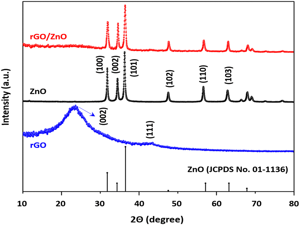 | ||
| Fig. 2 XRD spectrum of the synthesized nanomaterials. | ||
![[double bond, length as m-dash]](https://www.rsc.org/images/entities/char_e001.gif) O stretching of the COOH group, respectively.68 Similar kinds of results were also observed in a previous study.69 In the case of the ZnO nanomaterial, the sharp peak at around 576 cm−1 corresponds to the characteristic Zn–O stretching vibrations, and a broad band at around 3431 cm−1 is due to the presence of the hydroxyl group.70 The peak observed at 893 cm−1 is due to the formation of tetrahedral coordination of zinc (Zn). Apart from that, there are several minute peaks observed at 1383 cm−1, 1628 cm−1 and 2925 cm−1, which can be attributed to asymmetric and symmetric CO stretching vibrations, and C–H stretching vibrations, respectively.71 Similarly, in the FTIR spectrum of the rGO/ZnO composite material, the characteristic peaks of both the pristine ZnO as well as pristine rGO are present. For instance, the peaks at 576 cm−1, 893 cm−1 and 1383 cm−1 correspond to ZnO, while the peaks at 1226 cm−1, 1584 cm−1, and 1726 cm−1 correspond to the rGO material, confirming the successful formation of the composite (Table 2).
O stretching of the COOH group, respectively.68 Similar kinds of results were also observed in a previous study.69 In the case of the ZnO nanomaterial, the sharp peak at around 576 cm−1 corresponds to the characteristic Zn–O stretching vibrations, and a broad band at around 3431 cm−1 is due to the presence of the hydroxyl group.70 The peak observed at 893 cm−1 is due to the formation of tetrahedral coordination of zinc (Zn). Apart from that, there are several minute peaks observed at 1383 cm−1, 1628 cm−1 and 2925 cm−1, which can be attributed to asymmetric and symmetric CO stretching vibrations, and C–H stretching vibrations, respectively.71 Similarly, in the FTIR spectrum of the rGO/ZnO composite material, the characteristic peaks of both the pristine ZnO as well as pristine rGO are present. For instance, the peaks at 576 cm−1, 893 cm−1 and 1383 cm−1 correspond to ZnO, while the peaks at 1226 cm−1, 1584 cm−1, and 1726 cm−1 correspond to the rGO material, confirming the successful formation of the composite (Table 2).
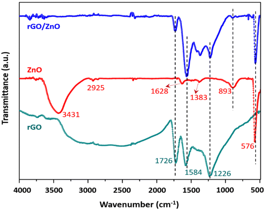 | ||
| Fig. 3 FTIR spectrum of the synthesized nanomaterials. | ||
| Peak position (cm−1) | Peak assignment |
|---|---|
| rGO | |
| 1226 | Ester (C–O–C) group stretching |
| 1584 | C–C (phenyl group) bond stretching |
| 1726 | CO stretching of COOH group |
| ZnO | |
| 576 | Zn–O vibrations (metal–oxygen stretching) |
| 893 | Tetrahedral coordination of zinc |
| 1383 | CO asymmetric stretching vibrations |
| 1628 | CO symmetric stretching vibrations |
| 2925 | C–H stretching vibrations |
| 3431 | Hydroxyl (–OH) group |
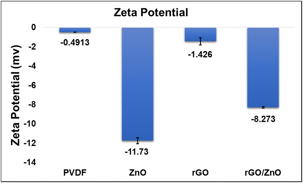 | ||
| Fig. 4 Zeta potential data of the synthesized materials. | ||
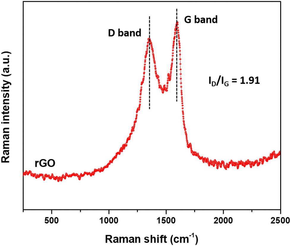 | ||
| Fig. 5 Raman spectrum of the synthesized rGO nanomaterial. | ||
3.2 Characterisation result of the membranes
 | ||
| Fig. 6 (i) Surface and (ii) cross-sectional FESEM images of (A) neat PVDF, (B) ZnO-PVDF, (C) rGO-PVDF, and (D) rGO/ZnO-PVDF membranes. | ||
In the cross-section images of the membranes, asymmetric finger-like structures with a small sponge layer were seen in the pure PVDF membrane. The finger-like structure extended and large sponge-like structures increased due to the incorporation of the additive materials of ZnO, rGO, and rGO/ZnO.53 This is mostly owing to the additives' hydrophilic properties, which increase the interchange effects of the solvent and non-solvent during the phase inversion process.72 The cross-sectional morphology was consistent with the water flux investigations.
Furthermore, FESEM-EDX mapping for carbon (C), oxygen (O), fluorine (F), and zinc (Zn) elements was performed to demonstrate the uniform dispersion and existence of ZnO and rGO/ZnO nanomaterials in the ZnO-PVDF and rGO/ZnO-PVDF membranes, as shown in Fig. 7.
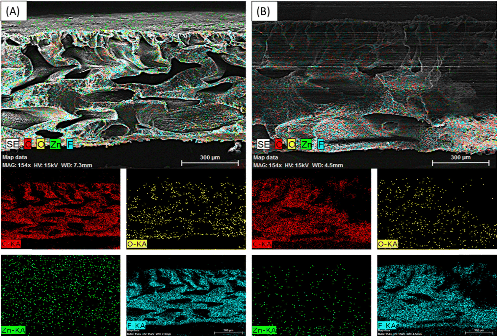 | ||
| Fig. 7 EDX mapping image of (A) ZnO-PVDF and (B) rGO/ZnO-PVDF membranes with C, O, Zn, and F elements. | ||
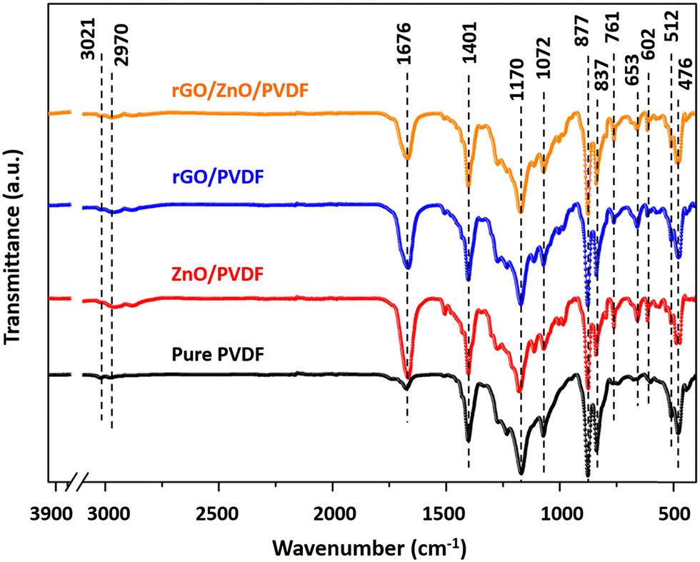 | ||
| Fig. 8 FTIR spectrum of the fabricated membranes. | ||
| Peak position (cm−1) | Peak assignment |
|---|---|
| 476 | Symmetric vibrations of O–C–O deformation |
| 602 | CF2 bending |
| 761 | CH2 rocking |
| 877 | C–H stretching modes |
| 1072 | C–C stretching modes |
| 1170 | Asymmetrical C–F stretching |
| 1401 | CH2 bending |
| 2970 | Symmetric stretching of CH2 group |
| 3021 | –CH2 group asymmetric stretching |
 | ||
| Fig. 9 (A) Contact angle and (B) mechanical strength of the synthesized membranes. | ||
The mechanical characteristics of all the fabricated membranes, as measured by tensile strength, are shown in Fig. 9B. PVDF is a mechanically strong polymer, and PVDF membranes have exceptional mechanical qualities when compared to other composite membranes. The result showed that the tensile strength of the neat PVDF membrane was ∼7.09 MPa. It is also similar to the findings of Pramono et al.8 In nanocomposite membranes, the increment in membrane porosity and agglomeration of the nanocomposite may lead to early breaking of the membrane, which decreases their mechanical strength.42 The tensile strength of the PVDF composite membranes after the incorporation of ZnO, rGO and rGO/ZnO nanomaterials are 2.82 MPa, 4.33 MPa, and 5.76 MPa, respectively. The improved tensile strength of the composite after rGO incorporation is due to the high mechanical strength of the rGO sheets, which have excellent interface adaptability in the PVDF polymer matrices and can enhance the mechanical stability of the rGO-PVDF and rGO/ZnO-PVDF nanocomposite membranes. When rGO and ZnO were incorporated together, they provided complementary reinforcement mechanisms that enhanced the overall mechanical stability of the membranes. The rGO can help in dispersing ZnO nanoparticles more evenly throughout the PVDF matrix as ZnO alone tends to agglomerate, and rGO can act as a stabilizing agent to keep ZnO particles well-dispersed. The combination of rGO/ZnO nanocomposite in the rGO/ZnO-PVDF membrane minimizes agglomeration and improves the dispersion of nanomaterials within the polymer matrix, leading to a more uniform reinforcement which provides improved stress distribution and mechanical strength. Furthermore, as demonstrated in FESEM experiments, membranes having large finger-like morphology, have higher tensile strength.73
| Membrane type | Contact angle (°) | Porosity (%) | Mean pore size (nm) | Rejection (%) | |
|---|---|---|---|---|---|
| BSA (%) | CBB dye (%) | ||||
| Pure PVDF | ∼78.14 | ∼39 | ∼10.1 | ∼4.41 | ∼1.15 |
| ZnO-PVDF | ∼63.18 | ∼59.31 | ∼13.29 | ∼33.07 | ∼38.23 |
| rGO-PVDF | ∼73.38 | ∼40.84 | ∼28.96 | ∼26.32 | ∼15.83 |
| rGO/ZnO-PVDF | ∼69.92 | ∼46 | ∼30.75 | ∼47.29 | ∼37.73 |
The pore sizes of the bare PVDF and modified membranes are important criteria for evaluating membrane performances. To obtain membrane pore size, the Guerout–Elford Ferry equation was used and the obtained data are presented in Table 4. A comparison between pure and nanocomposite PVDF membranes showed that the incorporation of the additives in the polymeric matrix had a positive effect on the mean pore size. However, the ZnO-PVDF membrane showed a lower pore size compared to other modified membranes due to the agglomeration of the smaller-sized ZnO nanomaterial into the polymer matrix. The incorporation of rGO sheets into a polymer matrix increases the membrane mean pore size (rm) because of its larger size and homogenous dispersion. The highest pore size was shown by the rGO/ZnO-PVDF membrane due to the addition of hydrophilic ZnO nanomaterials onto the rGO sheets, which prevents their agglomeration into a polymer matrix. This kind of phenomenon was also reported by various researchers.19,74–76
3.3 Antibacterial activity of the nanomaterials
The obtained disk diffusion results revealed that the green synthesized ZnO nanomaterial had a good antibacterial property, which is also observed in the rGO/ZnO nanocomposite. In Fig. 10, gentamicin, which is an antibiotic; and blank, which is a water-dipped disk, were used as a positive control and negative control. The ZnO-loaded disk showed a zone of inhibition around 16.5 mm, and the rGO/ZnO-loaded disk showed a zone of inhibition around 14.9 mm (including the diameter of the disk). The rGO sheets did not show a zone of inhibition. The incorporation of these bactericidal nanomaterials into the polymer membranes may provide them with antibacterial and anti-biofouling properties.77,78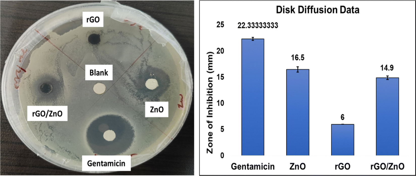 | ||
| Fig. 10 Disk diffusion data of the synthesized nanomaterials. | ||
3.4 Membrane filtration properties
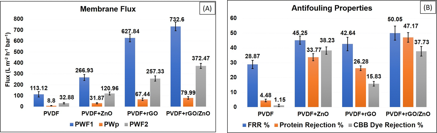 | ||
| Fig. 11 (A) Membrane flux, (B) protein rejection, and antifouling properties of the prepared membranes. | ||
The pore diameters of the membranes revealed that all membranes are ultrafiltration compatible. The high pore-size membrane demonstrated strong rejection, which might be attributed to its high hydrophilicity or low contact angle. However, the PVDF membrane with a small pore size showed reduced rejection, which can be explained by its hydrophobic character.
3.5 Antifouling properties of the membranes
The antifouling characteristics of the synthesized membranes were estimated using the approach described in Section 2.9. All produced membranes had their initial pure water flux (Pwf1), BSA protein flux (Pwp), and pure water flux (Pwf2). During the pure water flux experiment, the membrane surface was cleaned. The BSA feed flux experiment revealed a reduction in flux owing to BSA fouling on the membrane surface. After water immersion, pure water fluxes in all the membranes were improved due to the elimination of loosely attached BSA protein from the membrane surface.According to these findings, the rGO/ZnO-PVDF membrane surface demonstrated better BSA protein removal compared to other membranes. The flux recovery ratio (FRR) is a crucial factor in membrane antifouling studies, and it is usually considered that higher FRR values indicate better antifouling performance. As demonstrated in Fig. 11B, all modified membranes had higher FRR values than the pure PVDF membrane. The rGO/ZnO-PVDF membrane had the best FRR value (50.05%) and demonstrated higher antifouling properties.
Many other researchers reported similar kinds of results, which are compared in Table 5. In comparison to others, our synthesized rGO/ZnO-PVDF membrane showed higher water flux with a moderate antifouling property. Also, various researchers confirmed that the incorporation of ZnO, as an antibacterial agent, into a polymer matrix increases the anti-biofouling behaviour of the synthesized nanocomposite membranes.48,79,80
| Membrane composition | Nanofiller concentration | Contact angle (°) | Porosity (%) | Mean pore size (nm) | Pure water flux (Pwf) | FRR (%) | Ref. |
|---|---|---|---|---|---|---|---|
| ZnO/PVC | 0.1 g ZnO | ∼53.58 | — | ∼311.08 | ∼122 L m−2 h−1 | ∼70 | 79 |
| ZnO/PEG/PEES | 1.5 wt% ZnO | ∼47.46 | ∼30.20 | ∼5.9 | ∼233.76 L m−2 h−1 | ∼76.30 | 80 |
| CuO/ZnO/PES | 0.2 wt% CuO/ZnO | ∼65.5 | — | ∼39.76 | ∼679.0 kg m−2 h−1 | ∼50.1 | 60 |
| GO/ZnO/PVDF | 0.2 wt% GO/ZnO | ∼49.8 | ∼66.07 | ∼43 | ∼170.73 L m−2 h−1 | ∼92.79 | 72 |
| rGO/ZnO/PES | 0.5 wt% rGO | ∼52.31 | ∼89.28 | ∼8.75 | ∼12 L m−2 h−1 | ∼82 | 49 |
| 0.5 wt% ZnO | |||||||
| SGO/ZnO/PES | 1 wt% SGO/ZnO | ∼51.9 | ∼74.8 | ∼11.76 | ∼152 L m−2 h−1 | ∼73.2 | 53 |
| rGO/ZnO/PES | 5 wt% rGO/ZnO | ∼70 | — | — | ∼641 L m−2 h−1 | — | 48 |
| rGO/ZnO/PVDF | 0.5 wt% rGO/ZnO | ∼69.92 | ∼46 | ∼30.25 | ∼732.6 L m−2h−1bar−1 | ∼50.5 | This work |
3.6 Antibacterial properties of the membranes
The obtained disk diffusion results revealed that only ZnO-PVDF and rGO/ZnO-PVDF nanocomposite membranes showed a zone of inhibition among all types of membranes. As earlier in Section 3.3, we said that both ZnO and rGO/ZnO nanocomposite materials had good antibacterial properties. The results confirm that the addition of these materials into the PVDF membrane gives them antibacterial properties. In Fig. 12, gentamicin as an antibiotic and blank, which is a water-dipped disk, were used as a positive control and negative control. The ZnO-PVDF and rGO/ZnO-PVDF nanocomposite membrane disks both showed a zone of inhibition around 10 mm (including the diameter of the disk). The rGO composite and pure PVDF membrane did not show a zone of inhibition.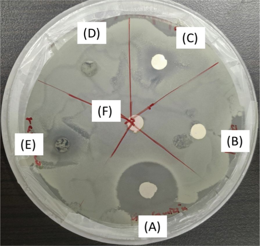 | ||
| Fig. 12 Disk diffusion test of the synthesized membranes against Bacillus subtilis, where A (gentamicin), B (only PVDF), C (ZnO), D (rGO), E (rGO/ZnO), and F represent water-dipped disk (blank). | ||
4. Conclusion
The addition of ZnO, rGO, and rGO/ZnO nanomaterials enhanced the PVDF membrane hydrophilicity, membrane flux, and antifouling performances. The incorporation of ZnO nanomaterial into rGO sheets not only increases the hydrophilicity of the rGO/ZnO nanocomposite but also provides bactericidal properties to them. So, the addition of this hydrophilic nanocomposite into the PVDF membrane matrix decreases the water contact angle and increases the membrane permeability, rejection, and flux recovery ratio (FRR) in comparison to the pure PVDF membrane. This might be due to rGO/ZnO's increased hydrophilicity, which allows for improved solvent migration from the polymer matrix to the non-solvent (water), thereby facilitating the creation of larger porosity and pore size. FESEM analysis of the membrane showed that the rGO/ZnO nanocomposite made finger-like microvoids and a sponge structure, which resulted in a higher flux of the membrane. Also, the rejection of BSA and CBB dye increased due to the negative charge provided by the ZnO in the rGO/ZnO nanocomposite. The antifouling study reveals that the rGO/ZnO-PVDF membrane had the highest FRR value of ∼50.05% among the various synthesized membranes. The disk diffusion data of the synthesized nanomaterials confirms their antibacterial activity and the addition of rGO/ZnO nanomaterial provides anti-biofouling behaviour to the polymer membranes by minimizing the adhesion of bacteria onto the membrane surface. Conducting such antibacterial tests against these bacteria can help in controlling the contaminants in both industrial processes and consumer products, demonstrating the practical relevance of the work. Based on the observed results, the rGO/ZnO-PVDF membrane holds significant potential for effectively reducing the pollutants from wastewater and may evolve as a high-performance multifunctional antifouling membrane with additional modification in the future.Author contributions
All authors have contributed to the study conception and design of the manuscript. Ankush Agrawal: material preparation, experimental designing, data collection and analysis, writing manuscript. Nishel Saini: data collection and analysis, writing manuscript. Kamlendra Awasthi: formal analysis and editing. Anjali Awasthi: formal analysis, conceptualization, supervision and editing. All authors read and approved the final manuscript.Data availability
The data obtained from the experiments conducted for this study has been included in the main manuscript in the form of figures and tables. No supplementary/public data/code/crystallographic data etc. have been used in the present manuscript.Conflicts of interest
The authors declare no conflict of interest.Acknowledgements
The author (Ankush Agrawal) acknowledges the Council for Scientific and Industrial Research (CSIR), Govt. of India, for funding assistance and the Materials Research Centre (MRC), MNIT Jaipur, for providing the characterization facilities.References
- A. Nagar and T. Pradeep, ACS Nano, 2020, 14, 6420–6435 CrossRef CAS PubMed.
- A. Agrawal, A. Sharma, K. K. Awasthi and A. Awasthi, Mater. Today Chem., 2021, 21, 100532 CrossRef CAS.
- A. Nasir, F. Masood, T. Yasin and A. Hameed, J. Ind. Eng. Chem., 2019, 79, 29–40 CrossRef CAS.
- D. Li, Y. Yan and H. Wang, Prog. Polym. Sci., 2016, 61, 104–155 CrossRef CAS.
- M. A. Shannon, P. W. Bohn, M. Elimelech, J. G. Georgiadis, B. J. Marĩas and A. M. Mayes, Nature, 2008, 452, 301–310 CrossRef CAS PubMed.
- M. Zahid, A. Rashid, S. Akram, Z. A. Rehan and W. Razzaq, J. Membr. Sci. Technol., 2018, 08, 1–20 Search PubMed.
- Y. Wen, J. Yuan, X. Ma, S. Wang and Y. Liu, Environ. Chem. Lett., 2019, 17, 1539–1551 CrossRef CAS.
- E. Pramono, A. L. Simamora, C. L. Radiman and D. Wahyuningrum, IOP Conf. Ser. Earth Environ. Sci., 2017, 75, 012027 CrossRef.
- D. Zou and Y. M. Lee, Prog. Polym. Sci., 2022, 128 Search PubMed.
- H. Wang and K. Ding, Membranes, 2022, 12, 216.
- N. Saini, A. Awasthi, K. Pandey and K. Awasthi, Eur. Phys. J.-Spec. Top., 2024 DOI:10.1140/epjs/s11734-024-01187-2.
- R. Meng, X. Wang, D. Li, K. Zhang, X. Li, Y. Li, L. Chen and L. Ci, Desalination, 2024, 587, 117919 CrossRef CAS.
- K. T. Huisman, M. H. Abdellah, D. S. Alvarez Sosa, F. R. Fernandes Simoes, B. Blankert, J. S. Vrouwenvelder and G. Szekely, Desalination, 2024, 582, 117604 CrossRef CAS.
- Z. Esmaili, Z. Sadeghian and S. N. Ashrafizadeh, J. Membr. Sci., 2023, 688, 122147 CrossRef CAS.
- P. S. Goh and A. F. Ismail, Desalination, 2018, 434, 60–80 CrossRef CAS.
- Y. T. Chung, E. Mahmoudi, A. W. Mohammad, A. Benamor, D. Johnson and N. Hilal, Desalination, 2017, 402, 123–132 CrossRef CAS.
- H. Rajabi, N. Ghaemi, S. S. Madaeni, P. Daraei, B. Astinchap, S. Zinadini and S. H. Razavizadeh, Appl. Surf. Sci., 2015, 349, 66–77 CrossRef CAS.
- M. Ahsani, H. Hazrati, M. Javadi, M. Ulbricht and R. Yegani, Sep. Purif. Technol., 2020, 249, 116938 CrossRef CAS.
- N. Nasrollahi, S. Aber, V. Vatanpour and N. M. Mahmoodi, Development of hydrophilic microporous PES ultrafiltration membrane containing CuO nanoparticles with improved antifouling and separation performance, Elsevier B.V., 2019, vol. 222 Search PubMed.
- N. Yaacob, P. S. Goh, A. F. Ismail, N. A. M. Nazri, B. C. Ng, M. N. Z. Abidin and L. T. Yogarathinam, Membranes, 2020, 10, 1–18 CrossRef PubMed.
- T. Marino, M. Boerrigter, M. Faccini, C. Chaumette, L. Arockiasamy, J. Bundschuh and A. Figoli, in Application of Nanotechnology in Membranes for Water Treatment, 2017 Search PubMed.
- A. Noormohamadi, M. Homayoonfal, M. R. Mehrnia and F. Davar, Environ. Technol., 2020, 41, 2683–2704 CrossRef CAS PubMed.
- X. Li, R. Pang, J. Li, X. Sun, J. Shen, W. Han and L. Wang, Desalination, 2013, 324, 48–56 CrossRef CAS.
- X. Zhao, Y. Chen, H. Xuan and C. He, New J. Chem., 2016, 40, 441–446 RSC.
- M. Yi, C. H. Lau, S. Xiong, W. Wei, R. Liao, L. Shen, A. Lu and Y. Wang, ACS Appl. Mater. Interfaces, 2019, 11, 15698–15708 CrossRef CAS PubMed.
- S. G. Kim, D. H. Hyeon, J. H. Chun, B. H. Chun and S. H. Kim, J. Membr. Sci., 2013, 443, 10–18 CrossRef CAS.
- H. Shi, F. Liu and L. Xue, J. Membr. Sci., 2013, 437, 205–215 CrossRef CAS.
- O. T. Mahlangu, R. Nackaerts, J. M. Thwala, B. B. Mamba and A. R. D. Verliefde, J. Membr. Sci., 2017, 524, 43–55 CrossRef CAS.
- H. Wu, B. Tang and P. Wu, J. Membr. Sci., 2014, 451, 94–102 CrossRef CAS.
- A. Khalid, A. Abdel-Karim, M. Ali Atieh, S. Javed and G. McKay, Sep. Purif. Technol., 2018, 190, 165–176 CrossRef CAS.
- J. Hong and Y. He, Desalination, 2014, 332(1), 67–75 CrossRef CAS.
- S. Balta, A. Sotto, P. Luis, L. Benea, B. Van der Bruggen and J. Kim, J. Membr. Sci., 2012, 389, 155–161 CrossRef CAS.
- L. Shen, X. Bian, X. Lu, L. Shi, Z. Liu, L. Chen, Z. Hou and K. Fan, Desalination, 2012, 293, 21–29 CrossRef CAS.
- C. P. Leo, W. P. Cathie Lee, A. L. Ahmad and A. W. Mohammad, Sep. Purif. Technol., 2012, 89, 51–56 CrossRef CAS.
- S. Zhao, W. Yan, M. Shi, Z. Wang, J. Wang and S. Wang, J. Membr. Sci., 2015, 478, 105–116 CrossRef CAS.
- W. Y. Pang, A. L. Ahmad and N. D. Zaulkiflee, J. Environ. Manage., 2019, 249, 109358 CrossRef CAS PubMed.
- S. Owais Mushtaq, R. Sharma, A. Agrawal, A. Sharma, S. Kumar, K. Awasthi, C. S. Yadav and A. Awasthi, Mater. Today Proc., 2022, 69, 74–81 CrossRef CAS.
- R. Sharma, A. Agrawal, A. Sharma, S. Kumar, P. K. Sharma, K. K. Awasthi, K. Pandey and A. Awasthi, Mater. Today Proc., 2022, 69, 1587–1595 CrossRef.
- N. T. Nguyen and V. A. Nguyen, J. Nanomater., 2020, 1768371 CAS.
- H. Huang, Y. Ying and X. Peng, J. Mater. Chem. A, 2014, 2, 13772–13782 RSC.
- A. T. Smith, A. M. LaChance, S. Zeng, B. Liu and L. Sun, Nano Mater. Sci., 2019, 1, 31–47 CrossRef.
- F. Kazemi, Y. Jafarzadeh, S. Masoumi and M. Rostamizadeh, J. Environ. Chem. Eng., 2021, 9(1), 104992 CrossRef CAS.
- O. T. Mahlangu, R. Nackaerts, B. B. Mamba and A. R. D. Verliefde, Water Sci. Technol., 2017, 76(3), 501–514 CrossRef CAS PubMed.
- T. D. Kusworo, F. Dalanta, N. Aryanti and N. H. Othman, J. Water Process Eng., 2021, 41, 102030 CrossRef.
- M. Kryuchkova, A. Danilushkina, Y. Lvov and R. Fakhrullin, Environ. Sci.: Nano, 2016, 3, 442–452 RSC.
- S. Liu, T. H. Zeng, M. Hofmann, E. Burcombe, J. Wei, R. Jiang, J. Kong and Y. Chen, ACS Nano, 2011, 5(9), 6971–6980 Search PubMed.
- E. L. Subtil, J. Gonçalves, H. G. Lemos, E. C. Venancio, J. C. Mierzwa, J. dos Santos de Souza, W. Alves and P. Le-Clech, Chem. Eng. J., 2020, 390, 124612 Search PubMed.
- W. Zhang, H. Huang and R. Bernstein, J. Colloid Interface Sci., 2022, 613, 426–434 CrossRef CAS PubMed.
- T. D. Kusworo, A. C. Kumoro, N. Aryanti and D. P. Utomo, J. Environ. Chem. Eng., 2021, 9, 106421 Search PubMed.
- G. Szekely, RSC Sustainability, 2024, 2, 871–880 RSC.
- A. Agrawal, R. Sharma, A. Sharma, K. C. Gurjar, S. Kumar, S. Chatterjee, H. Pandey, K. Awasthi and A. Awasthi, Environ. Sci. Pollut. Res., 2023, 30, 86328–86337 CrossRef CAS PubMed.
- M. F. Zainuddin, N. H. Nik Raikhan, N. H. Othman and W. F. H. Abdullah, IOP Conf. Ser.: Mater. Sci. Eng., 2018, 358, 012046 Search PubMed.
- G. Boopathy, A. Gangasalam and A. Mahalingam, J. Chem. Technol. Biotechnol., 2020, 95, 3012–3023 CrossRef CAS.
- Y. L. Thuyavan, N. Anantharaman, G. Arthanareeswaran and A. F. Ismail, J. Chem. Technol. Biotechnol., 2016, 91, 2568–2581 CrossRef CAS.
- J. Zhang, Z. Xu, W. Mai, C. Min, B. Zhou, M. Shan, Y. Li, C. Yang, Z. Wang and X. Qian, J. Mater. Chem. A, 2013, 1, 3101–3111 RSC.
- S. Ayyaru and Y. H. Ahn, J. Membr. Sci., 2017, 525, 210–219 CrossRef CAS.
- K. Chand Gurjar, A. Agrawal, S. Kumar, R. Sharma, K. Pandey, H. Pandey and A. Awasthi, Mater. Today Proc., 2023, 95, 61–66 CrossRef CAS.
- A. Agrawal, A. Sharma, G. Awasthi, Kamakshi, A. Awasthi and K. K. Awasthi, Toxicity assessment and antibacterial activity of ZnO nanoparticles, in Nanostructured Zinc Oxide, ed. K. Awasthi, Metal Oxides, Elsevier, 2021, pp. 511–552.
- X. Zhao, J. Ma, Z. Wang, G. Wen, J. Jiang, F. Shi and L. Sheng, Desalination, 2012, 303, 29–38 CrossRef CAS.
- N. Nasrollahi, V. Vatanpour, S. Aber and N. M. Mahmoodi, Sep. Purif. Technol., 2018, 192, 369–382 CrossRef CAS.
- B. Li and Y. Wang, Superlattices Microstruct., 2010, 47, 615–623 CrossRef CAS.
- D. C. Marcano, D. V. Kosynkin, J. M. Berlin, A. Sinitskii, Z. Sun, A. Slesarev, L. B. Alemany, W. Lu and J. M. Tour, ACS Nano, 2010, 4, 4806–4814 CrossRef CAS PubMed.
- G. Yasin, M. Arif, M. Shakeel, Y. Dun, Y. Zuo, W. Q. Khan, Y. Tang, A. Khan and M. Nadeem, Adv. Eng. Mater., 2018, 20, 1701166 CrossRef.
- B. M. Gunasekaran, S. Manoj, G. K. Rajendran, S. Muthiah, N. Nesakumar, J. R. Sivanesan, S. Srinivasan, A. K. Gunasekaran and G. Gopu, J. Mater. Sci.: Mater. Electron., 2023, 34, 1–23 CrossRef.
- S. Agarwal, S. Kumar, H. Agrawal, M. G. Moinuddin, M. Kumar, S. K. Sharma and K. Awasthi, Sens. Actuators, B, 2021, 346, 130510 CrossRef CAS.
- S. Kumar, S. D. Lawaniya, S. Agarwal, Y.-T. Yu, S. R. Nelamarri, M. Kumar, Y. K. Mishra and K. Awasthi, Sens. Actuators, B, 2023, 375, 132943 CrossRef CAS.
- S. Liu, Z. Wang, Y. Zhang, Z. Dong and T. Zhang, RSC Adv., 2015, 5, 91760–91765 RSC.
- H. V. Kiranakumar, C. S. Naveen, R. Thejas, G. D. Prasanna, G. Nagaraju and M. V. Murugendrappa, Sens. Technol., 2024, 2, 2310479 CrossRef.
- H. Liu, T. Kuila, N. H. Kim, B. C. Ku and J. H. Lee, J. Mater. Chem. A, 2013, 1, 3739–3746 RSC.
- K. Kacem, S. Ameur, J. Casanova-Chafer, M. F. Nsib and E. Llobet, J. Mater. Sci.: Mater. Electron., 2022, 33, 16099–16112 CrossRef CAS.
- S. Mahalakshmi, N. Hema and P. P. Vijaya, Bionanoscience, 2020, 10, 112–121 CrossRef.
- S. Ayyaru, T. T. L. Dinh and Y. H. Ahn, Chemosphere, 2020, 241, 125068 CrossRef CAS PubMed.
- M. Alhoshan, J. Alam, L. A. Dass and N. Al-Homaidi, Adv. Polym. Technol., 2013, 32, 21369 CrossRef.
- V. Vatanpour, S. S. Madaeni, R. Moradian, S. Zinadini and B. Astinchap, J. Membr. Sci., 2011, 375, 284–294 CrossRef CAS.
- Z. Wang, H. Yu, J. Xia, F. Zhang, F. Li, Y. Xia and Y. Li, Desalination, 2012, 299, 50–54 CrossRef CAS.
- S. Zinadini, A. A. Zinatizadeh, M. Rahimi, V. Vatanpour and H. Zangeneh, J. Membr. Sci., 2014, 453, 292–301 CrossRef CAS.
- W. Zhang, Y. Yang, E. Ziemann, A. Be’Er, M. Y. Bashouti, M. Elimelech and R. Bernstein, Environ. Sci.: Nano, 2019, 6, 3080–3090 RSC.
- A. R. Malik, S. Sharif, F. Shaheen, M. Khalid, Y. Iqbal, A. Faisal, M. H. Aziz, M. Atif, S. Ahmad, M. Fakhar-e-Alam, N. Hossain, H. Ahmad and T. Botmart, J. Saudi Chem. Soc., 2022, 26, 101438 CrossRef CAS.
- Q. F. Alsalhy, F. H. Al-Ani, A. E. Al-Najar and S. I. A. Jabuk, Chem. Eng. Process., 2018, 130, 262–274 CrossRef CAS.
- M. Purushothaman, A. Harikrishnan, P. Senthil Kumar, J. George, G. Rangasamy and V. K. Vaidyanathan, Environ. Res., 2023, 216, 114696 CrossRef CAS PubMed.
| This journal is © The Royal Society of Chemistry and the Centre National de la Recherche Scientifique 2024 |