
Electric field-assisted laser ablation fabrication and assembly of zinc oxide/carbon nanocomposites into hierarchical structures for supercapacitor electrodes
Natalie N.
Tarasenka
 *a,
Vladislav G.
Kornev
a,
Mikhail I.
Nedelko
a,
Hanna M.
Maltanova
b,
Sergey K.
Poznyak
b and
Nikolai V.
Tarasenko
a
*a,
Vladislav G.
Kornev
a,
Mikhail I.
Nedelko
a,
Hanna M.
Maltanova
b,
Sergey K.
Poznyak
b and
Nikolai V.
Tarasenko
a
aB.I. Stepanov Institute of Physics, National Academy of Sciences of Belarus, Minsk 220072, Belarus. E-mail: natalie.tarasenka@dragon.bas-net.by
bBelarusian State University, Research Institute for Physical Chemical Problems, Minsk 220006, Belarus
First published on 23rd November 2023
Abstract
One of the major challenges in the field of electrochemical energy storage device performance improvement is the development of suitable synthetic materials for electrodes that can provide high power and high energy density features combined with their long-term stability. Here, we have developed a novel two-step approach based on DC glow discharge plasma pre-treatment of a carbon cloth substrate followed by electric field-assisted laser ablation for the synthesis of ZnO/C nanocomposites in a liquid and their simultaneous assembly into hierarchically organized nanostructures onto the pre-processed carbon cloth to produce a supercapacitor electrode. To form such nanostructures, a processed carbon cloth was included in the electrical circuit as a cathode during laser ablation of zinc in water, while a zinc target served as an anode. A series of studies have been performed to explore the structure, morphology, composition and electrochemical characteristics of the synthesized ZnO/C nanocomposites. Application of the external field provided additional possibilities for tuning the particle morphology. The parameters of the obtained nanostructures were shown to depend on the direction of the applied electric field and liquid composition. SEM studies revealed a nanoflower-like morphology of the prepared nanomaterial having potential in supercapacitor applications due to a large surface area. The ZnO/C nanoflowers, deposited onto a carbon cloth substrate, were tested for energy storage by cyclic voltammetry (CV) and galvanostatic charge–discharge (GCD) analysis. The results showed a pseudocapacitor behavior with a maximum specific capacitance of about 3045 F g−1 (at a scan rate of 1 mV s−1). These results demonstrate a promising storage efficiency of the synthesized ZnO/C nanocomposite as a material for supercapacitors.
1. Introduction
Development of environmentally-friendly and renewable energy sources such as ion batteries, fuel cells and supercapacitors that can meet the growing demand for energy sources has recently become a topic of major significance.1–3 Supercapacitors, including electric double-layer capacitors (EDLCs) and pseudocapacitors (PC), depending on the dominant charge storage mechanism, play the leading role among the indicated energy storage devices due to high energy density, fast charging and long lifespans.4,5 Since the performance of supercapacitors is determined by the composition and configuration of an electrode material, extensive research efforts have been attempted to design suitable electrode materials capable of improving the electrochemical properties of supercapacitors.6,7 As a result, numerous possible configurations were proposed and tested, mostly based on carbon-based materials and transition metal oxides as common materials of EDLCs and PC, respectively.8,9 Among carbon-based materials, graphene, graphene oxide,10 carbon nanotubes11 and carbon nanofibers12 have been recently studied and utilized as electrode materials in EDLCs. However, the obtained values of capacitance and energy density using EDLCs are still not very high. Therefore, novel strategies should be developed for the improvement of the major parameters of supercapacitor electrodes.As a possible route for enhancing the supercapacitor electrochemical performance, formation of nanocomposite electrode materials by assembling carbon materials and transition metal oxides has been recognized to be effective.13,14 Nanosized materials offer a row of improved characteristics, which can significantly contribute to the specific capacitance enhancement of electrochemical energy storage devices owing to the larger surface area of nanomaterial-based electrodes.10 Among many transition metal oxides, ZnO represents a promising electrode-building material owing to its abundance, stability and low toxicity. In addition, nanosized ZnO properties are morphology-dependent while ZnO can be nanostructured in a variety of morphologies by different fabrication methods. A number of publications have been devoted to the preparation of ZnO nanoparticles (NPs);13–16 however, in previous works, insufficient attention was paid to the deposition of NPs onto surface layers and the corresponding preparation of the substrate surface. Nevertheless, as will be shown in this work, these factors play an important role in further increasing the capacitive properties of the created energy storage devices.
Another strategy for enhancing the supercapacitor electrochemical performance can be premised on the development of novel methods for deposition and assembling of nanomaterials into organized binder-free electrodes. Typically, the supercapacitor production includes the addition of a binder, most commonly polymers such as polyvinylidene fluoride (PVDF) or polytetrafluoroethylene (PTFE). Despite increasing the electrode stability and its mechanical properties, this additive induces undesired interfacial resistance in the system that hinders the electron transport between carbon and metal oxide counterparts.17 Therefore, it is of interest to utilize various binder-free nanomaterials with a hierarchical structure as electrode materials that allows boosting the electrochemical performance by reaching nanoscale dimensions, enhancing the electrode surface area and combining EDLC and PC active materials. Recently, the development and utilization of hierarchical nanostructures has become an emerging field in modern research showing promising behavior for a broad range of technological applications, especially for catalysis, sensing, water splitting, energy generation and storage.18 Such architecture enables the achievement of novel functions and distinctive properties such as development of a large surface area with plenty of active sites, formation of developed diffusion channels and diverse junction interfaces. Specifically, the application of hierarchical structures in supercapacitor electrode construction provides advantages such as an improved surface-to-volume ratio, abundant electrochemically active sites facilitating direct electron transport and enhanced electrolyte penetration, and avoidance of random aggregation of particles and agglomeration at the surface. Self-assembly of nanoparticulate structures with their oriented growth enables contact between nano-sized constituent layers that allows avoiding a typical problem of increased resistance in nanostructured materials.18 As recent works demonstrated, utilization of hierarchical nanostructures allows a significant enhancement of the supercapacitor electrode performance. In ref. 19, binder-free hierarchical NiCo2O4@NiO was grown on a C cloth substrate that allowed reaching a high specific capacitance of 921.9 mF cm−2 at 2 mA cm−2 and high cycling stability. In the work of Bao et al.20 the developed hydrothermally grown hierarchical NiCo2O4@MnO2 core–shell nanosheets allowed further increasing the specific capacitance up to 1595.1 F g−1. Wang et al. obtained ultra-high values of the specific capacitance (3871.2 F g−1 at 1 A g−1) and good cycle life span with capacitance retention of 87.5% after 6000 cycles at 5 A g−1 for hydrothermally grown hierarchical ZnCo layered double hydroxides.21
Despite the reported advances, the commonly known methods for the hierarchical nanostructure formation are complex and costly. Generally, the strategies used for hierarchical nanostructure fabrication mainly rely either on self-assembly of the constituent nanostructures or otherwise on oriented template-mediated synthesis of the nanomaterial with the addition of specific capping agents or surfactants for inducing NP anisotropic growth on the surface.22 Therefore, most methods used for the hierarchical nanostructures formation are based on hydrothermal20–23 or solvothermal synthesis24,25 that generally implies complex multi-stage processes with the use of hazardous materials. Alternatively, metal–organic frameworks can be applied to selectively grow hierarchical structures as demonstrated in ref 24,26,27.
Here, we report a new two-step approach based on the combination of laser- and plasma-assisted synthesis for ZnO and ZnO/C hierarchical nanostructure formation in aqueous solutions with their simultaneous electrodeposition from a colloidal solution onto a carbon substrate for electrode material fabrication. As is known, plasma-assisted synthesis based on pulsed laser ablation in liquid (LAL) and on gaseous discharge in contact with liquid are versatile and “green” techniques applicable for nanomaterial synthesis of a broad range of compositions and structures. These techniques provide non-inhalable colloidal NPs with no residues or chemical by-products, while often no further purification is required. The approach developed in the present work for the preparation of binder-free and flexible supercapacitor electrodes based on a modified carbon cloth allows gaining the main benefits of the plasma-assisted NP synthesis in liquids: versatility, simplicity, possibility of control over the particle formation processes along with the deposition of homogeneous nanostructured layers. Hereby, the synergy of these methods has been used: a first stage of plasma-assisted pre-treatment enables uniform deposition of a thin film of ZnO NPs, while laser ablation in an external field utilizes the created active sites to produce uniform hierarchical nanostructures consisting of ZnO/C nanoflowers that showed a high capacitance in the preliminary electrochemical assessment. A distinctive feature of the developed method is the combination of the nanomaterial synthesis process with their assembly into nanostructured layers on a carbon substrate during the synthesis.
2. Experimental
2.1. Materials
A zinc metal plate (purity 99.9%, Alfa Aesar, UK) was used as an anode in plasma treatment of C-cloth substrate experiment and a target in the laser ablation process. The carbon cloth was purchased from Chemical Co. Ltd (Svetlagorsk, Belarus). All liquid chemicals (double distilled water, ethanol) were of analytical grade and used without any further purification.2.2. Zinc oxide/carbon nanocomposite preparation
In the experiments, to obtain a binder-free ZnO/C/carbon cloth flexible supercapacitor electrode, a two-step combined plasma-laser approach was developed and implemented. In the first stage, carbon cloth was modified using atmospheric pressure microplasma ignited in contact with a liquid (Fig. 1a). The ignition of a microplasma of the gas–liquid interfacial discharge occurred by application of a high voltage using a DC power supply (2.6–3.2 kV) to a stainless steel capillary cathode and a Zn anode, the latter being immersed in the liquid (distilled water). A cathode with an inner diameter of 500 μm and a length of 5 cm was located at a distance of 2 mm above the liquid surface. For the plasma generation, Ar working gas was flown through the capillary cathode at a rate in the range of 10–45 sccm measured using a mass flow controller. As a result, the discharge was ignited between the capillary cathode and the liquid surface. The resulting current was limited to 4 mA by introduction of a ballast resistor (0.1–0.4 MΩ) that improved the stability of the discharge. To enable simultaneous modification of the substrate, carbon cloth was connected in parallel to the capillary cathode with an additional ballast resistor between them (6 MΩ). This scheme enabled the formation of zinc ions, clusters and colloidal NPs with their deposition onto a carbon cloth and thin film fabrication.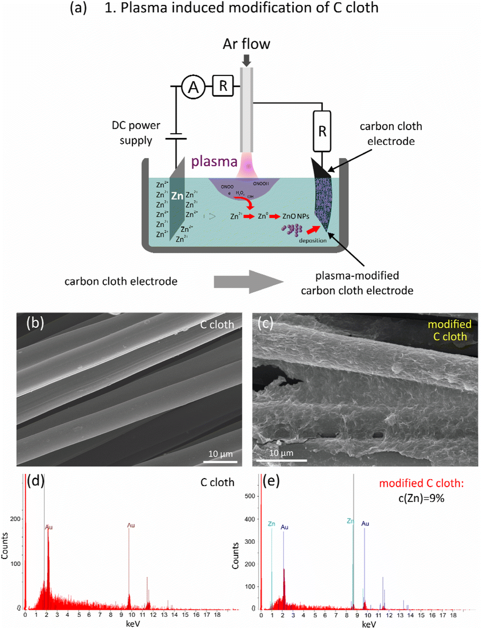 | ||
| Fig. 1 Plasma-induced modification of a C cloth substrate: (a) schematic illustration of the setup developed for plasma-assisted modification. (b and c) SEM images of the carbon cloth before (b) and after plasma modification (c); (d and e) EDX spectra of the carbon cloth before (d) and after plasma modification (e). | ||
The processed carbon cloth was further used as a substrate for ZnO/C nanomaterial deposition during electric field-assisted laser ablation in liquid. For this, it was connected as a cathode to a DC power supply that provided a voltage of 200 V, while a pure Zn plate was selected to be an anode and a target in the laser ablation process at the same time. Here, to limit the current, an additional resistance of 41 kΩ was connected in series to the Zn target/anode. Both electrodes were immersed in a cell filled with a liquid having a volume of 50 ml. The developed setup is schematically presented in Fig. 3a. For the ablation, the radiation of the fundamental harmonic of a YAG:Nd3+ laser was used with the following parameters: wavelength 1064 nm, pulse duration 10 ns, repetition rate 10 Hz, power density on the target surface 5.5 × 10⁸ W cm−2, and ablated spot size 200 μm. The laser operated in a double-pulse mode giving a sequence of doubled pulses with an interpulse delay of 10 μs.
For the formation of ZnO nanostructures and ZnO/C nanocomposites, the bottom Zn electrode was subjected to laser ablation either in distilled water (sample ZnO) or carbon NP colloid (sample ZnO/C). To prepare C NP colloid, the scheme developed in ref. 28 was used. First, the graphite powder was suspended in distilled water using ultrasonication for 1 hour. After that, laser irradiation was utilized to produce a colloidal solution of C nanomaterials. For this, the beam of the fundamental harmonic of the YAG:Nd3+ laser (1064 nm, pulse duration 10 ns, repetition rate 10 Hz) was focused into the suspension using a 75 mm lens. Here, a single pulse mode of the nanosecond laser was used for the C NP synthesis process that was performed for 30 min till it acquired a brownish color. After that, 3 ml of this colloid was added to the distilled water during Zn ablation in the electric field. After the deposition, the electrode was dried in air. The total mass of the loaded nanomaterial onto the carbon cloth was 1.45 mg.
2.3. Material characterization
The morphology and structure of the formed composite electrode were evaluated using the scanning electron microscopy (SEM) technique with a SEM microscope SUPRA 55WDS (Carl Zeiss, Germany). The microscope was equipped with an energy-dispersive X-ray (EDX) detector, which enabled determination of the elemental composition of the prepared nanocomposites.Additional information on the phase composition, crystal and defect structure of the prepared nanocomposites was obtained from the results of X-ray diffraction (XRD), Raman and Fourier transform infrared (FTIR) spectroscopy. For the XRD analysis, the colloidal solution of NPs that remained in the reaction cell after the synthesis, was deposited onto a glass substrate and dried at 100 °C and then analyzed using a DRON-2 diffractometer (Russia) using a CuKα source. The XRD analysis was performed at room temperature in the 2θ range from 10 to 80°. For Raman and FTIR spectroscopy, the colloidal solution was deposited onto an aluminum foil and dried at 100 °C to remove the excess water. The FTIR spectra were collected using a Fourier spectrometer Nexus (Termo Nicolet, USA) in the 4000–300 cm−1 range. Raman spectra were collected in the range of 100–2000 cm−1 using a scanning probe confocal microscope/spectrometer NanoFlex (Solar LS, Belarus) with a laser excitation source at 470 nm.
The electrochemical performance of the electrodes prepared was evaluated by measurement of current–potential dependencies in a three-electrode scheme (Fig. 5a), which included a working electrode (WE), a counter electrode (CE), and a reference electrode (RE). In the electrochemical experiments performed, a platinum electrode was used as a counter electrode, a saturated calomel electrode (SCE) as a reference electrode, and ZnO/C nanostructures on carbon cloth as a working electrode. The measurements were performed at room temperature in 1 M Na2SO4 using a potentiostat Autolab PGSTAT 302N (Metrohm Autolab B.V., Netherlands). The mass and size of the electrode active material were 1.45 mg and 202.7 mm2, respectively.
In addition to cyclic voltammetry (CV), galvanostatic charge and discharge (GCD) and electrochemical impedance spectroscopy (EIS) were also used to evaluate the electrochemical performance of the prepared ZnO/C hybrid electrode. For tests of CV and galvanostatic charge–discharge (GCD), the voltage range was set at 0–0.6 V, and EIS spectra were obtained over a frequency range from 10 mHz to 10 kHz.
3. Results and discussion
3.1. Plasma treatment of the C-cloth substrate
In the first step of a ZnO/C/carbon cloth supercapacitor electrode preparation, plasma treatment of a carbon cloth substrate was implemented enabling the formation of a thin layer of seed ZnO NPs on its surface. This step was used to impart hydrophilicity, ensure adhesion to the hydrophobic surface of carbon and allow further uniform growth of ZnO/C nanocomposites during the second stage of laser ablation in an applied electric field. Laser ablation in an applied electric field was used to enable the simultaneous production of non-spherical NPs with their deposition onto a pre-treated substrate, which can be any conductive material. Here, carbon cloth was selected as a current collector for supercapacitor electrode application. Carbon-based materials have attracted much attention recently as stable, low-cost conductive materials, characterized by chemical inertness, mechanical strength and a large surface area, which is especially promising for the manufacturing of flexible and wearable electronic devices. However, carbon-based materials are known to be hydrophobic and have weak adhesion of active materials to their surfaces, which sufficiently hinders their application for the production of supercapacitor electrodes with high mechanical/electrochemical stability. As a result, to achieve good wettability, adhesion and uniformity of the forming composite films, pre-treatment of the substrate is required, while this problem is often overlooked in the literature. The reported surface treatment methods typically rely on gas-phase or liquid-phase oxidative processes performed chemically or electrochemically and catalytic oxidation.29 As a result of oxidative treatment, oxygen-containing groups, such as C–OH, –O–C–, –O–C![[double bond, length as m-dash]](https://www.rsc.org/images/entities/char_e001.gif) O or –COOH, are formed on the carbon cloth surface that increases the polarity of the substrate and enhances its wettability.29,30 For example, Zheng et al.30 achieved the formation of oxygen-containing moieties after treatment of the pre-oxidized annealed polyacrylonitrile cloth with a mixture of concentrated H2SO4 and HNO3. In a number of works, the wettability of carbon fibers was enhanced by ultrasonic cleaning31 or surface modification.30,32,33 The latter can be implemented using the deposition of thin films of a polymer material or by the creation of functional groups. Namely, in ref. 33, a polydopamine layer was grown on the C substrate surface that enabled the improvement of C cloth hydrophilicity and the growth of uniform polyaniline coatings on it.
O or –COOH, are formed on the carbon cloth surface that increases the polarity of the substrate and enhances its wettability.29,30 For example, Zheng et al.30 achieved the formation of oxygen-containing moieties after treatment of the pre-oxidized annealed polyacrylonitrile cloth with a mixture of concentrated H2SO4 and HNO3. In a number of works, the wettability of carbon fibers was enhanced by ultrasonic cleaning31 or surface modification.30,32,33 The latter can be implemented using the deposition of thin films of a polymer material or by the creation of functional groups. Namely, in ref. 33, a polydopamine layer was grown on the C substrate surface that enabled the improvement of C cloth hydrophilicity and the growth of uniform polyaniline coatings on it.
In this work, to modify a bare C cloth surface, an approach based on atmospheric pressure DC discharge generated in contact with the liquid was utilized.34,35 The scheme of the plasma-assisted setup used at the first stage is shown in Fig. 1a. As a result of a high-voltage application, the plasma near the surface of a liquid is ignited that initiates several processes influencing the composition of both the liquid and C cloth. First, it is known that the interaction of helium or argon plasma jets with a liquid results in the creation of reactive oxygen and nitrogen species (RONS), which further participate in a number of chemical processes and can oxidize the surface of the C cloth, thereby improving its wettability and adhesion.
Among the typically observed oxidizing species, atomic oxygen (O), hydroxyl radical (OH), hydrogen peroxide (H2O2), ozone (O3), and molecular oxygen in excited states (e.g. single delta oxygen O2 (1D) and superoxide (O2−)), are typically registered.36 Besides, as the discharge was ignited at atmospheric pressure in ambient air, the admixture of molecular nitrogen and oxygen was typically found entering the plasma that produces nitrogen species in solution, such as atomic nitrogen (N), nitric oxides (NOx), HNO3, etc., while dissolution of nitrogen related species results in acidification of the solution.37 These species can further penetrate into a liquid to a certain depth, depending on their energy and lifetime, participating in further chemical processes.36 Thus, the reactive oxygen and nitrogen species may interact with a carbon cloth inserted into the liquid with the formation of oxygen-containing functional groups, such as hydroxyl, carbonyl and carboxylic moieties.
Another plasma-induced process is the formation of NPs resulting from the metal ion reduction in solution. As a Zn anode is immersed in a liquid, its dissolution produces Zn2+ ions, which are further reduced by the species formed in plasma, resulting in the formation of zero-valent Zn, which further nucleates and grows in a liquid or on the carbon cloth surface with the formation of a thin film of NPs. Here, the reducing agents are electrons, ions and radicals such as atomic H, H−, H2, and H2O2, which are produced as a result of the plasma–liquid interaction and participate in chemical reactions with liquid components. In fact, plasma-produced species have different lifetimes and different reducing abilities38 that can be utilized for the control and tailoring of the synthesis process. The strongest reducing agents formed are electrons from bulk plasma, and secondary electrons from ion irradiation on the liquid surface. After entering a liquid, free electrons undergo solvation to form eaq−, which due to high reducing ability (E = −2.87 V vs. standard hydrogen electrode (SHE)39) can reduce most of the metal ions in an aqueous solution. However, eaq− has a short lifetime (from several ns up to microseconds depending on the medium37).
Among the other short-living species, free electrons, secondary electrons, atomic H, H− are typically distinguished. The long-living species such as H2 and H2O2, are also formed. Still, because the majority of plasma-produced species have short lifetimes, the most important reaction zone during plasma generation in contact with a liquid is the plasma–liquid interface and a thin liquid layer up to several millimeters below the liquid surface. However, it is known that under the application of the electric field, the ions as well as charged NPs, will migrate towards the oppositely charged electrode, that can result in their movement to the liquid surface and the C cloth substrate, which are negative electrodes in the developed setup. As a result, this enables the deposition of seed NPs on the carbon cloth, thus modifying its surface, increasing its wettability and adhesion of the ZnO/C nanocomposites during the second stage of laser ablation in an applied electric field. Furthermore, Zn NPs may undergo oxidation due to the interaction with oxidizing species, such as H2O2 or O2, with the formation of ZnO NPs. Furthermore, the pre-coating with grown seed ZnO NPs can be used as a template for oriented growth of hierarchical nanostructures on a supporting substrate that was indeed observed in SEM images shown in Fig. 3. The idea of seed-mediated growth of oriented nanostructures was previously reported for the formation of ZnO and TiO2 nanorod arrays.18
The formation of a thin seed layer of electrodeposited ZnO NPs was proved by SEM and EDX analysis, and the corresponding results are presented in Fig. 1. In fact, comparison of the SEM images of the carbon cloth before (b) and after plasma electrodeposition allows us to conclude that a thin uniform layer is deposited onto a carbon cloth after plasma treatment. The EDX spectra prove the introduction of Zn element to the carbon substrate after plasma modification. It should be noted that the thin films covering the carbon cloth fibers are rather uniform that allows suggesting that they are most probably comprised of closely packed small seed NPs. However, as ZnO has semiconducting properties, the deposition of particles is limited by the conductivity of the thus modified substrate. Therefore, this technique allows the formation of only thin layers of fine NPs. For supercapacitor applications, a large surface area is preferable which is typical of anisotropic nanomaterials. Their formation and deposition were achieved in the next step of laser ablation in an applied electric field.
3.2. Laser ablation in an applied electric field
The application of an electric field to a metal target during laser ablation was shown to have several distinctive features that allow both altering the NP synthesis process as well as achieving the simultaneous deposition into ordered structures with a developed surface. The first feature allows the production of anisotropic non-spherical NPs (Fig. 2 and 3). To study their morphology, the NPs formed in the colloid were collected and deposited onto an Al substrate for SEM investigations. The resulting morphology was found to depend on the polarity of a target/electrode and values of an applied voltage, along with a solvent composition. In contrast to the typically observed spherical NPs formed by laser ablation in liquids, the SEM images of ZnO NPs prepared in water using a voltage of 200 V applied to a Zn target revealed flower-like structures with petal-like planes closely packed around the center of each nanoflower (Fig. 2a and b).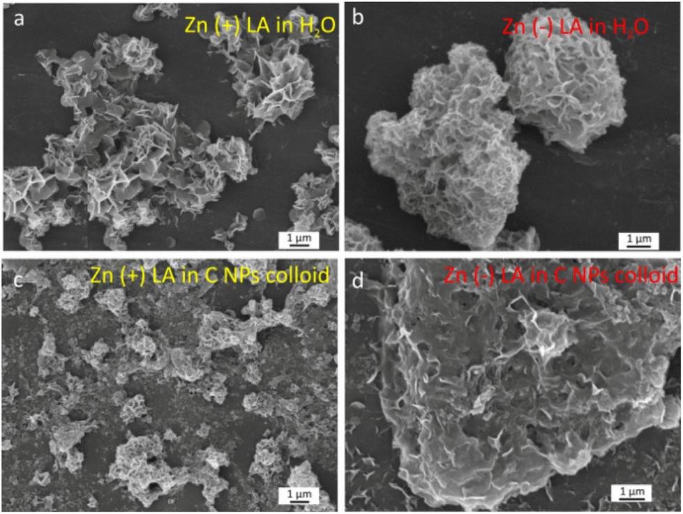 | ||
| Fig. 2 SEM images of nanoparticles in the colloids obtained by the laser ablation of Zn in solution, depending on the polarity and liquid composition: (a) Zn anode in water, (b) Zn cathode in water, (c) Zn anode in the C NP colloid, (d) Zn cathode in the C NP colloid. | ||
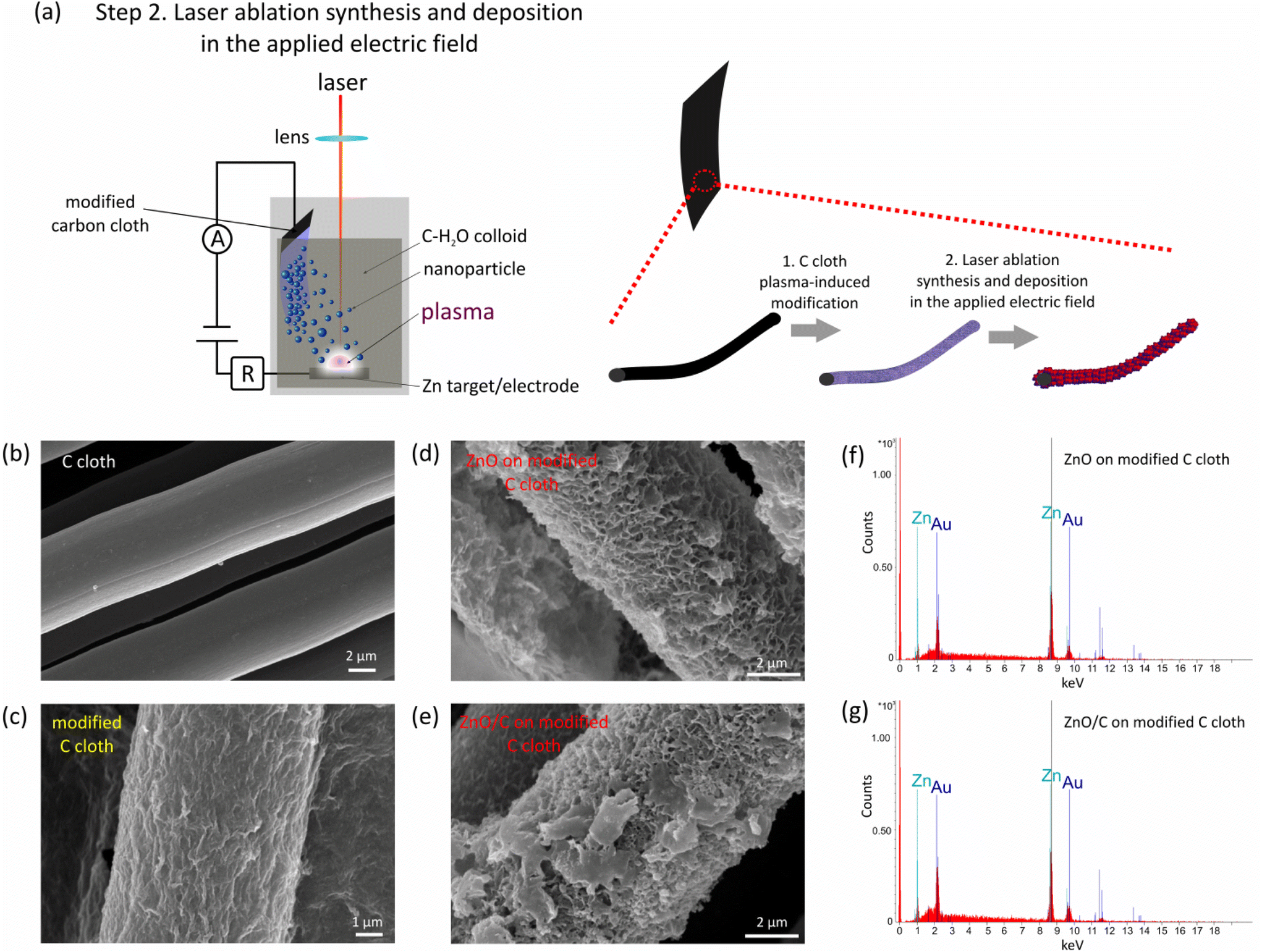 | ||
| Fig. 3 (a) Schematic illustration of the preparation procedure of composite ZnO/C nanoparticles. (b–e) SEM images: of a bare C cloth (b), of a C cloth substrate after the first stage of plasma-induced modification (c), and after the laser-induced ZnO and ZnO/C nanocomposites deposition by the laser ablation of a Zn anode in water (d) and the C NP colloid (e); (f and g) EDX spectra of the samples after laser-induced deposition of ZnO (f) and ZnO/C (g) nanoparticles, respectively. | ||
In ZnO nanoflowers, nanoscale ZnO properties are combined with a high surface area that provides a promising building block for multifunctional hierarchical structures. Currently, the formation of nanoflowers has been achieved in a number of works, which are mostly based on chemical methods.40–42 Their formation mechanism is usually attributed either to the self-assembly of primary seed NPs having similar atomic arrangements40,41 or to the anisotropic growth of elongated structures on the surface of primary seeds using different templates or capping agents.42 In our case, both effects should be considered. First, the application of an external field may alter the formation mechanisms of NPs in plasma, resulting in elongated structures or nanosheets. Afterwards, the applied electric field may induce self-assembly of the formed nanomaterial into hierarchical flower-like nanostructures.
If the ablation synthesis is performed in C NP colloids, the particles have a flake-type morphology when Zn is connected to the circuit as a cathode (Fig. 2d), but in the anode case, the resulting sponge-like structure was revealed (Fig. 2c). Such morphology is especially promising for supercapacitor applications due to a large surface area.
The second feature allows assembling the forming nanomaterial on the negative electrode simultaneously with the synthesis of NPs. In fact, the deposition of particles on the negative electrode surface observed during synthesis turned out to be a convenient method for the formation of thin film structures of non-spherical morphology. The formation of the non-spherical nanostructures uniformly covering the surface of the carbon fibers is evidenced by SEM images shown in Fig. 3d and e. The SEM images of a bare C cloth and the sample after the first stage of plasma modification are shown in Fig. 3b and c for comparison.
Using Zn anode ablation both in water and C NP colloids, hierarchical flake-like nanostructures were produced, which result from the assembly of the formed nanoflowers on the pre-processed C cloth. Furthermore, the nanostructured layers cover the fibers uniformly, that can be attributed to good adhesion after the plasma processing. EDX measurements (Fig. 3f and g) prove the formation of Zn-containing layers on the surface, while the concentration of Zn in the samples after laser ablation significantly increases as compared to the samples after the first stage of plasma treatment, indicating thicker ZnO layers deposition after laser ablation. It should be noted, however, that in Fig. 3e, nanostructures of other morphology are deposited on the surface, most probably being the agglomerates of mostly spherical NPs. It can be assumed that as the thickness of the ZnO layer covering the substrate increases, its conductivity decreases that consequently may level the influence of an applied electric field and result in common spherically-shaped NP formation. In this case, to enhance the further growth of non-spherical NPs and their assembly into thicker layers, an increase in the applied voltage can be used.
Thus, the developed two-step approach allowed the synthesis and assembly of the ZnO/C nanomaterials onto the C cloth. These uniformly distributed non-spherical ZnO/C particles are expected to enhance the electrochemical performance of supercapacitor electrodes through better utilization of the electrode material during electrolyte ion intercalation and electrochemical reactions.
3.3. Structural analysis
To reveal the inner structure of the formed nanomaterials, FTIR, Raman and XRD studies were performed. The results of FTIR analysis in the range 300–4000 cm−1 of the samples prepared by laser ablation of a Zn anode in water (black line) and in a carbon NP colloid (red line) are presented in Fig. 4a. As can be concluded from the FTIR analysis, in both cases, laser ablation results in the formation of a ZnO phase that is proved by the observation of the bands at around 350–600 cm−1 attributable to the Zn–O stretching modes.43–45 In the case of ZnO/C nanocomposites, two peaks at around 427 and 555 cm−1 were found that are in agreement with the typically observed ZnO FTIR band splitting for anisotropic ZnO nanomaterials. For example, the splitting into two IR peaks has been observed in the case of ZnO nanorods in ref. 46 that were attributed to the TO- and LO-frequency modes. In addition, the peaks at around 3400 cm−1 attributable to the stretching vibrations of the O–H group and related to the presence of water molecules from atmospheric moisture on the surface of NPs were found in both samples.47,48 Several peaks attributable to the adsorption of molecular CO2 from the atmosphere were also detected. For the sample prepared by laser ablation of a Zn anode in water, these were the peaks centered at around 829, 1357 and 1500 cm−1. The peak at 829 cm−1 can be related to the out-of-plane deformation mode (π(CO3)), while the peaks at 1357 cm−1 and 1500 cm−1 can be assigned to the vibrations of polydentate carbonate (O–C–O) or adsorbed carboxylate M–CO2− groups.49–51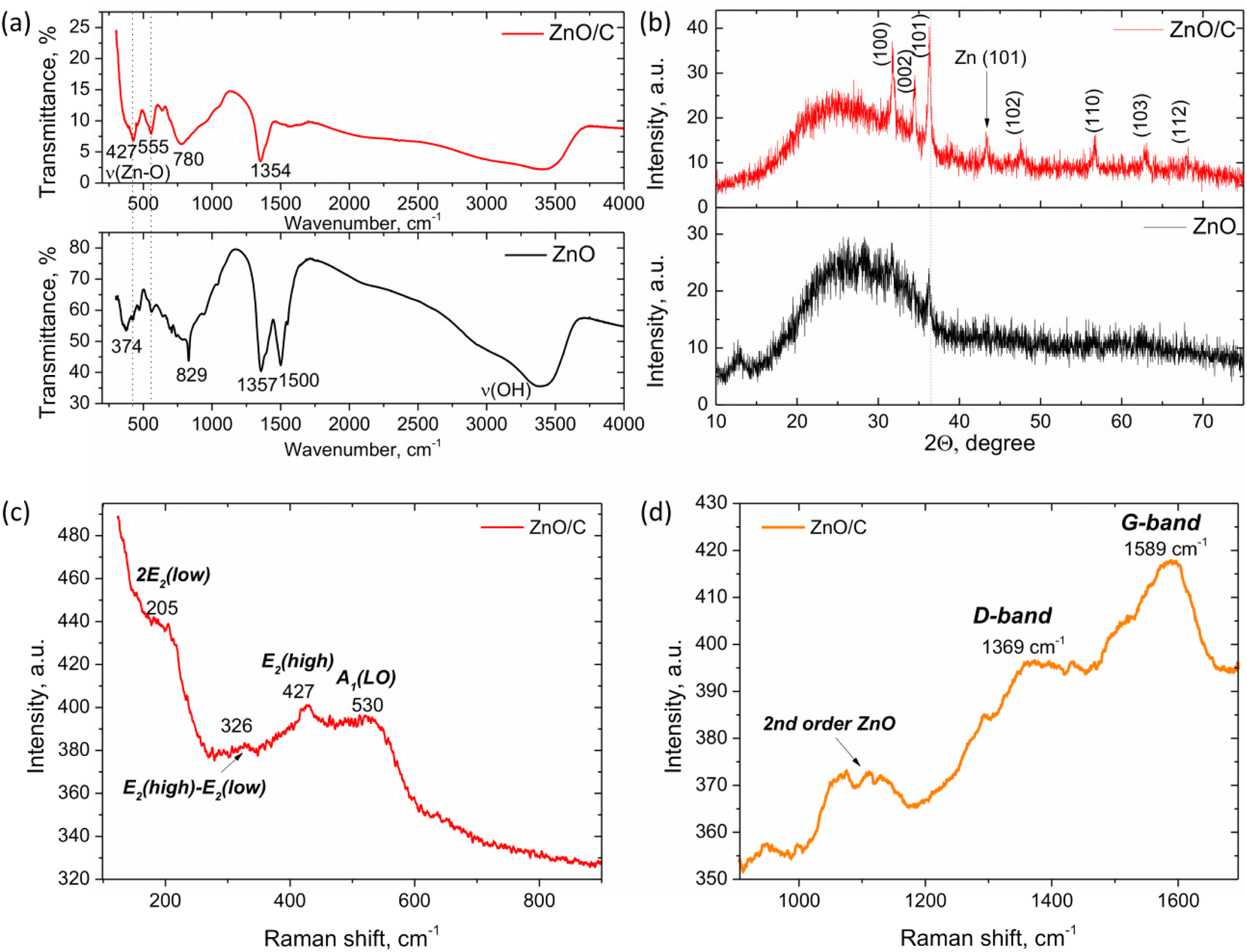 | ||
| Fig. 4 Structural characterization of the ZnO and ZnO/C nanostructures prepared by the laser ablation of a Zn (+) target in an applied electric field: (a) FTIR spectra; (b) XRD patterns; (c) and (d) Raman spectra in the 100–900 cm−1 (c) and 900–1700 cm−1 (d) ranges. | ||
It is noteworthy that for the sample prepared in distilled water, the peak corresponding to the Zn–O bond stretching vibration shifts to lower wavenumbers. This behavior can be related to the strains and disorder introduced into NPs due to the conditions of their formation in a non-equilibrium plasma. This conclusion is in agreement with the results of XRD and Raman studies of this sample that also prove the distorted lattice of the NPs.
The XRD patterns of the samples prepared in water and the C NP colloid are presented in Fig. 4b. In the case of the colloid prepared in water, the major feature is a broad “halo” in the range of 15–40° that can be attributed to the distorted and amorphous phases present in the sample, that is consistent with the FTIR results discussed above. However, besides the halo, several weak peaks are also distinguishable at around 31.73° and 36.21° that correspond well to the diffraction from (100) and (101) planes of the wurtzite-type zinc oxide (space group P63mc, JCPDS: 89-1397). When laser ablation is performed in the carbon NP colloid, the nanostructures obtained are characterized by the improved crystallinity, as can be concluded from the XRD pattern of the corresponding sample (Fig. 4b, red curve).
Here, the intensive peaks characteristic of X-ray diffraction from the crystal planes of the wurtzite ZnO phase are observed. The major peaks are positioned at 31.71°, 34.51°, 36.29°, 47.51°, 56.67°, 63.05° and 68.17° that correspond to the diffraction from the (100), (002), (101), (102), (110), (103) and (112) planes of hexagonal ZnO, respectively. However, the “halo” band is also observed, which can be related to a certain degree of strain and distortion in the NPs. In addition, it can be attributed to graphene nanostructures, which are typically characterized by a broad peak in the range of 20–30°.52,53 Besides, a peak at around 43.27° was also found, which can be related either to graphene phases or to the impurity of metallic Zn in the sample formed during laser ablation. It is noteworthy that no graphite peaks were observed in the XRD pattern of the ZnO/C sample.
Additional information about the crystal and defect structure of the prepared nanomaterials was obtained from Raman spectroscopy performed at room temperature in the range 100–1700 cm−1, as shown in Fig. 4c and d. As known, ZnO can crystallize in several crystal structures, with the hexagonal wurtzite type of space group P63mc being the most stable of them at room temperature. This structure is characterized by the existence of optical phonon modes at the Γ point of the Brillouin zone given by the equation:54Γopt = A1 + 2B1 + E1 + 2E2. Among these modes, A1, E1, and E2 modes are Raman active, while B modes are typically silent and are not active in Raman spectra. Besides, A1 and E1 modes represent polar branches that are split into longitudinal optical (LO) and transversal optical (TO) components with different frequencies.
For the sample prepared by laser ablation of a Zn anode in a C NP colloid, the typical features found in the Raman spectra are observed at 205, 326, 427, 530, 1100, 1369 and 1589 cm−1. The peak at 427 cm−1 can be attributed to the E2high mode that is typically associated with the oxygen sublattice vibrations and is characteristic of the wurtzite ZnO formation.48 Besides, a broad band at around 530 cm−1 corresponds to the A1(LO) mode, that is generally attributed to the formation of crystal defects in ZnO, such as oxygen vacancies VO55 or Zn interstitials.48 Another evidence of ZnO lattice distortion is the observation of several second-order Raman modes. Namely, the mode at 327 cm−1 is one of the typical second-order vibrations observed due to the enhancement of inactive phonons because of the disorder. This band can be tentatively assigned to the E2high–E2low second order Raman mode.56 The band at 205 cm−1 can be attributed to the 2E2(low) vibrational mode.55,57 Besides, a broad band in the range of 1060–1130 cm−1 is observed, which can be the result of the overlap of several multi-phonon bands. In ref. 58, the band at 1065 cm−1 was related to the A1(TO) + E1(TO) + E2L multi-phonon scattering mode, while the peak at around 1110 cm−1 was attributed to the acoustic combination of A1 and E2 modes.
Apart from the ZnO Raman scattering, broad bands at 1369 cm−1 and 1589 cm−1 were also observed in Fig. 4d. According to the position and shape of these bands, they can be ascribed to the D- and G-bands of carbon nanomaterials.52,59,60 The G-band is known to appear in carbon-based structures and is related to the C–C stretching vibrations in the graphite ring, while the D-band is defect-induced and originates from the breathing mode of aromatic rings. Therefore, the D-band appears in the distorted carbon structures, and relation of its intensity to the intensity of the G-band can be used to establish the level of disorder in carbon nanostructures. The observation of the carbon-originated Raman modes, along with the ZnO-related vibrational modes, allows concluding simultaneous presence of these materials in the produced nanostructures with the formation of a nanocomposite.
Thus, the prepared nanostructures contain defects proved by Raman and XRD studies, which can participate in the electrochemical processes during charging/discharging cycles of the supercapacitor electrode and can be used for its performance enhancement, as shown below.
3.4. Electrochemical test
The capacitive characteristics of the synthesized ZnO/C nanocomposite material were investigated by cyclic voltammetry (CV). In addition, galvanostatic charge–discharge tests, as well as electrochemical impedance spectroscopy measurements were carried out to evaluate the capacitance performance of the electrode. The electrochemical measurements were conducted using a three-electrode cell as shown in Fig. 5a. The resulting current–potential curves for the ZnO/C nanostructured working electrode are shown in Fig. 5b and c.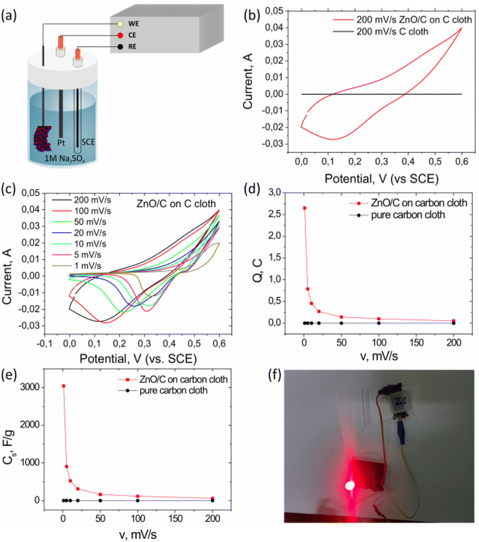 | ||
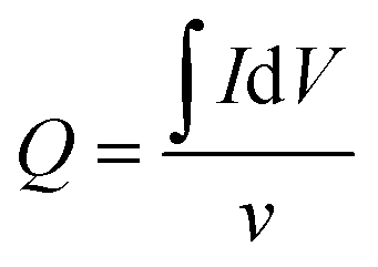
| Fig. 5 Electrochemical studies of the ZnO/C electrode: (a) three-electrode scheme used for current–potential measurements, (b) comparison of the current–potential curves for the ZnO/C nanocomposite electrode with that for the pure carbon cloth at a scan rate of 200 mV s−1, (c) current–potential curves for the ZnO/C electrode measured at different scan rates in the range from 1 to 200 mV s−1; the dependence of the stored charge (d) and specific capacitance (e) of the nanostructured ZnO/C electrode on the scan rate, respectively. Fig. (f) represents the results of an LED ignition using the developed electrode. | ||
First, since the composites were grown on a carbon cloth substrate, which can also be active in the charge storage processes due to double electric layer properties, the CV curves for the obtained nanostructured electrode were compared with the corresponding results for a bare C cloth substrate in the same potential window (0–0.6 V vs. SCE) and at the same scanning rate (200 mV s−1) (Fig. 5b).
As can be concluded from this comparison, application of a designed hierarchical nanostructured electrode allows to significantly increase the registered values of the output current, indicating a high conductivity of the prepared nanostructured electrode and low internal resistance.61 Besides, the stored charge is significantly higher for ZnO/C as compared to the bare C substrate, as can be seen from the increase in the area under the CV curve. It should be taken into account that the mass of the carbon cloth substrate is significantly (several orders of magnitude) larger than the active mass of the grown nanomaterial (1.45 mg) that allows us to conclude a prevailing contribution from the pseudocapacitive storage mechanism attributable to ZnO nanostructures, while the contribution from a carbon cloth substrate to the total capacitance of the developed electrode was negligible.
The shape of the CV curves observed for nanostructured ZnO/C electrodes with several peaks is close to that typically observed for pseudo-capacitive materials. This shape is known to depend on the mechanism of charge accumulation in the electrode: in the case of a double electric layer, the curves have rectangular shapes, while under prevailing pseudocapacitance mechanisms quasi-rectangular cyclic voltammograms are observed.3,61
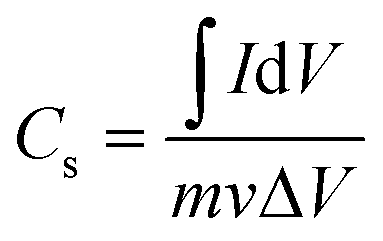
Further information about the underlying mechanisms of charge storage in the nanostructured electrode was obtained from the dependencies of CV curves on the scanning rate for the nanostructured ZnO/C electrodes shown in Fig. 5c. The CV curves were recorded for various scanning rates in the range of 1–200 mV s−1 in the potential window of 0–0.6 V vs. SCE. Upon the decrease of the scanning rate from 200 mV s−1 to 1 mV s−1, the distinctive peaks in the curves measured for the nanostructured ZnO/C electrodes became more pronounced, while their shift depending on the scan rate was detected. As the scan rate increased, the oxidation peaks shifted to a more positive value with the simultaneous shift of the reduction peaks to a more negative potential. This behavior is typical of pseudocapacitive electrode materials.62,63
Typically, the peaks in the CV curves of the metal oxide materials are attributed to the faradaic redox reactions initiated at the metal oxide surface. In the case of ZnO nanostructures, the origin of the observed peaks can be related to the processes of intercalation/deintercalation of alkali metal ions (Na+) by the electrode material according to the reaction: ZnO + Na+ + e− ↔ ZnONa.64–67 In general, the shape of the CV curves is mainly preserved for all scanning rates, indicating the fast kinetics of reactions at the ZnO/C nanocomposites surface.62 As for the bare cloth substrate, as could be expected, it was weakly active in the process of charge accumulation by the electrode, demonstrating a curve close to the rectangular shape typical to electrical double layer capacitors,66 while the area of cyclic voltammograms is several times smaller than that for the ZnO/C electrode.
The obtained CV curves were used to calculate the specific capacitance of the working electrode based on the estimation of the accumulated charge Q:13
 | (1) |
Therefore, the value of the specific capacitance Cs can be estimated using the following relation (2):
 | (2) |
The highest value of specific capacitance for ZnO/C nanocomposite electrodes calculated from CV curves was found to be ∼3045 F g−1 at a scanning rate of 1 mV s−1. The calculated values of specific capacitance and stored charge for the nanostructured ZnO/C electrode were significantly higher than those for bare C cloth (2.4 mF g−1 at 1 mV s−1), thus emphasizing the prevailing pseudocapacitive contribution to the total capacitance associated with ZnO/C nanostructures.13 Both the stored charge as well as specific capacitance were found to be influenced by the scanning rate. The corresponding dependencies of Q and Cs on the scanning rate are presented in Fig. 5d and e, respectively. As can be seen from these figures, the specific capacitance and stored charge of the ZnO/C nanocomposite material is much higher than that of the bare C cloth at the same scanning rate. It was also found that the values of the accumulated charge and capacitance decrease on increasing the scanning rate from 1 to 200 mV s−1. This behavior can be explained by the limited diffusion of electrolyte ions penetrating the electrode pores at high scanning rates. As a result, the entire surface is not involved in the charge storage process, but only the nearest to the surface areas, which accordingly reduces the accumulated charge and the corresponding capacitance.65,68
To further investigate the electrochemical behavior of the ZnO/C nanocomposite, galvanostatic charge–discharge (GCD) testing was carried out in the potential window from 0 to 0.6 V. Fig. 6 displays the galvanostatic charge–discharge curves of the ZnO/C electrode at various current values ranging from 0.5 to 5.0 mA (correspondingly, at current densities varying from 0.3 to 3.5 A g−1). The curves do not have linear triangular shapes usually observed in the case of electric double layer storage mechanism prevalence,66 but distorted, that agrees with the results of CV analysis. The unsymmetrical pattern of GCD curves most probably arises from the pseudocapacitive nature and surface processes at the electrode. Thus, the observed shape of GCD curves confirms a hybrid mechanism of the capacitance involving both electric double layer storage and pseudocapacitive mechanism. With the decrease of current density, the electrode discharge time increases, which is a typical behavior of the GCD curves of the nanostructured supercapacitor materials and is related to reduced specific capacitance and faster discharge rate at higher current densities.61,69
 | ||
| Fig. 6 Charge–discharge curves of the ZnO/C electrode at different current densities in the electrochemical cell. | ||
From the galvanostatic charging/discharging curves the specific capacitance was calculated following the equation
 | (3) |
By calculation, the specific capacitance of ZnO/C tested at a current density of 0.3 A g−1 was 272.0 F g−1, remaining still relatively high at higher current densities and decreasing evidently only at a current density of 7.0 A g−1 (108.6 F g−1) with a capacitance retention rate of 40% indicating the relatively good rate capability of the synthesized nanocomposite at high current densities.
The energy density (E, W h kg−1) and power density (P, W kg−1), which are generally known as major criteria for evaluation of the supercapacitors, can be calculated from galvanostatic tests by the following equations: E = [Cs(ΔV)2]/2 and P = E/Δt. The prepared ZnO/C nanocomposite supercapacitor electrode provided the highest specific energy density of 11.7 W h kg−1 at a specific power density of 1244 W kg−1 under a current value of 5 mA (current density of 3.5 A g−1).
Electrochemical impedance spectroscopy (EIS) was used to further study the resistance behavior and charge-transfer kinetics at the interface of the ZnO/C nanocomposite electrode and electrolyte. As impedance is determined by the amount of opposition to the current under the applied voltage, in the case of a supercapacitor electrode with the charge transfer processes occurring at the electrode surface, the change in the impedance can be associated with the adsorption of the reacting species, ion diffusion, and charge transfer. These processes are determined by the morphology and composition of the electrode, as well as the structure of the electrode–electrolyte interface and the type of electrolyte used. As a result, all the physico-chemical processes occurring in the system during electrochemical reactions can be represented by typical AC elements such as resistors and capacitors.70 Usually, the results of the EIS measurements are represented as Nyquist and Bode plots. The Nyquist plot of the ZnO/C nanocomposite electrode obtained in the 10 kHz–10 mHz frequency range is presented in Fig. 7. Generally, a shape of the Nyquist plot has three main regions depending on the frequency: a semi-circle arc at higher frequencies, a steep slope at lower frequencies, and these regions are connected by a short Warburg region related to the mass transfer of ions to and from the electrode–electrolyte interface region.14 The semi-circle arc results from the parallel combination of resistance and capacitance and is attributed to the charge transfer resistance and double layer capacitance at the electrode–electrolyte interface. If the kinetics of the charge transfer process in the material is fast, the diameter of semi-circle would be rather small.
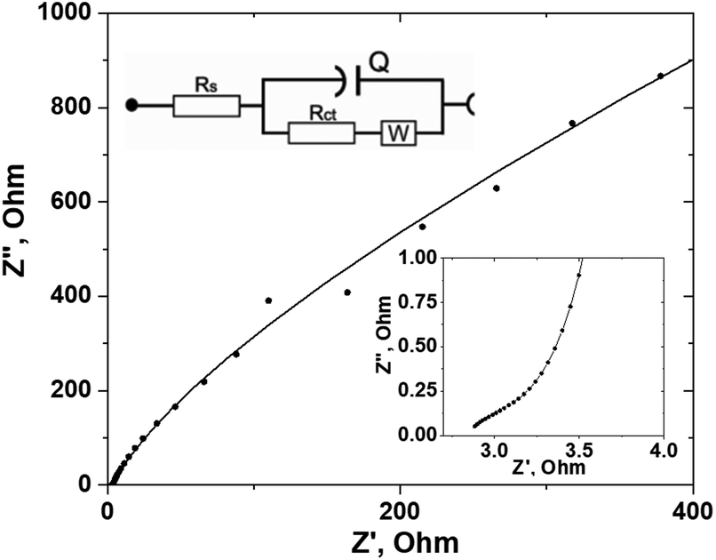 | ||
| Fig. 7 Measured (dots) and fitted (line) Nyquist plot for the ZnO/C electrode. An equivalent circuit used for the fitting of the EIS spectrum and magnified Nyquist curve part in the high-frequency range are shown as insets. | ||
In the high-frequency region, ion diffusion is limited, therefore only charge transfer processes occur. In this region, the x-intercept of the real part (Z′) of the Nyquist curve reflects the internal resistance (Rs), originated from such sources as the electrolyte ionic resistance, the internal resistance of the electrode material, and the interface electrolyte–electrode resistance.70 In our case, the Rs value would also depend on the contact resistance between ZnO NPs and the carbon cloth substrate.
The measured EIS spectrum was fitted using an equivalent circuit model shown in the inset of Fig. 7. The impedance information, including the internal resistance (Rs), Warburg impedance (W) and charge transfer resistance (Rct), was determined from the EIS data and is displayed in Table 1. Pseudocapacitance (CPE) is related to the capacitor layer formed during charge and discharge.
| Element | Parameter | Value | Estimated error (%) |
|---|---|---|---|
| R s | R | 3.12 Ω | 1.23 |
| R ct | R | 1.29 kΩ | 26.82 |
| CPE | Y 0 | 8.11 mS sn, n = 0.895 | 3.07 |
| W | W | 1.73 mS s1/2 | 22.93 |
| χ 2 | 0, 155 |
As it follows from the determined data shown in Table 1, the prepared ZnO/C electrode has a rather low internal resistance Rs (3.12 Ω) and a charge transfer resistance Rct (1.29 kΩ) that indicates high surface wettability and conductivity of the prepared nanocomposite and is important for active ion transport at the electrode–electrolyte interface having a positive effect on the rate performance of the electrode. The EIS results are in agreement with the CV data presented above.
Comparison of the obtained capacitance values with the previously reported ones allows us to conclude that the developed technique enables the formation of the electrode material with the performance among the highest reported to date. This can be explained with several reasons. First, the formation of nanoscale ZnO/C composites can be responsible for the remarkable supercapacitor performance. The complementary interaction between carbon and ZnO counterparts in the nanocomposite allows obtaining both EDLC and PC charge storage mechanisms, that is consistent with the previous reports on the formation of hybrid metal oxide–carbon nanostructures.71–73 Second, further enhancement of electrochemical performance can be attributed to the non-spherical flower-like morphology of ZnO/C nanocomposites and their uniform assembly into the hierarchical nanostructures. As discussed above, such material architecture provides a developed surface with multiple active sites that enhances the electrolyte ion intercalation and allows a better charge transfer process. For instance, by achievement of a hierarchical structure, ZnO/Co3O4 nanobundles arrays reported in ref. 74 exhibited a remarkable specific capacitance of up to 1983 F g−1 at a current density of 2 A g−1, while Zheng et al.75 achieved a specific capacitance of 3724 F g−1 at a current density of 1 A g−1 for hierarchical NiCo–S nanosheet arrays. Third, the formation of a binder-free electrode, as discussed above, ensures close contact between nanostructured counterparts, thereby reducing the interfacial resistance effects. As it was observed in the literature,76,77 this results in the materials with an increased capacitance due to fast electron transfer with numerous channels for ion diffusion. In ref. 78, this strategy enabled an electrode material with a capacity of 1476 F g−1 at 1.5 A g−1. Finally, the formation of defects in the ZnO structure, detected using XRD and Raman spectroscopy, can also have an impact on the performance of the electrode material. According to several reports,13,61,78,79 ZnO intrinsic defects, such as oxygen vacancies, can provide ion intercalation sites, which can further play a significant role in surface charge transfer processes, thus increasing the specific capacitance and cycling stability. In our case, most probably the high values of the specific capacitance are a result of the combined influence of all these effects.
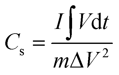
Thus, it has been shown that due to their large surface area and superior electrochemical performance, the developed hierarchical nanostructured ZnO/C nanocomposites can be used as an active material for supercapacitor electrode fabrication. Their assembly on a carbon cloth substrate provides flexibility, which is especially in demand for a wide range of modern devices. Fig. 5f illustrates that the supercapacitor assembled using the prepared ZnO/C electrodes can deliver an energy density sufficient for lighting up red and green LEDs with working potentials of 2.4 V and 3.0 V, respectively.
4. Conclusions
To conclude, we demonstrated the preparation of binder-free and flexible supercapacitor electrodes based on carbon cloth modified with as-grown ZnO/C nanoflowers. To form the electrodes, a two-step approach was developed and implemented. In the first stage, plasma pre-processing of a C cloth substrate was performed using the developed setup based on atmospheric pressure DC discharge plasma. In the second stage, the processed carbon cloth was included in the electrical circuit as a cathode during electric field-assisted laser ablation synthesis of the ZnO/C nanomaterial in liquids, while a zinc target served as an anode. It has been shown that under the application of an external electric field to a Zn target immersed in a liquid, nanomaterials of non-spherical morphology are formed. Their assembly during laser ablation in an electric field results in the formation of hierarchical nanostructures with a developed surface that allowed improving the electrochemical performance in the process of supercapacitor electrode charge storage.It has been found that the uniformity of deposition and the overall electrochemical performance of the deposited nanostructured electrodes can be significantly improved if plasma pre-processing of the substrate is used. As a result of C cloth surface modification, enhancement in adhesion of the forming nanocomposites to the C cloth surface was observed that can be attributed to several processes: increase of C cloth wettability, increase of the number of active sites on the surface for subsequent bonding with ZnO/C nanocomposites, and formation of a thin layer of seed ZnO NPs that act as a coupling layer by bonding to both the C cloth and ZnO/C nanocomposite in the next stage of deposition.
The electrodes’ morphology, structure, and electrochemical performance have been systematically investigated. The wurtzite-type ZnO inner structure of the composite was proved by XRD, FTIR and Raman techniques. The fabricated ZnO/C-based flexible electrode shows a high specific capacitance (3045 F g−1 at 1 mV s−1). A uniform non-isotropic hierarchical structure observed as a result of the synthesis can be attributed to seed-mediated electrodeposition from a colloidal solution.
Author contributions
Natalie N. Tarasenka: conceptualization, methodology, investigation, formal analysis, validation, visualization, writing – original draft, and writing – reviewing and editing; Vladislav G. Kornev: methodology, investigation, data curation, and formal analysis; Mikhail I. Nedelko: methodology, validation, and supervision; Hanna M. Maltanova: electrochemical measurements, formal analysis, and data curation; Sergey K. Poznyak: electrochemical measurements, formal Analysis, and writing – reviewing and editing; Nikolai V. Tarasenko: conceptualization, methodology, investigation, supervision, and writing – reviewing and editing.Conflicts of interest
There are no conflicts to declare.Acknowledgements
The work was partially financed by the National Academy of Sciences of Belarus under the project Convergence 2.2.05, the State Program for Scientific Research of Belarus “Chemical processes, reagents and technologies” (Project No. 2.1.04.02), and by the Belarusian Foundation for Fundamental Researches under Grants No. F21KOR-006, F22SRBG-008 and F23RNF-156. The authors are also grateful to Dr Grigory Rimsky for the XRD measurements, Dr A. Karoza for FTIR investigations, and Dr Anastasia Tabolich for the Raman measurements.References
- T. Kim, W. Song, D. Y. Son, L. K. Ono and Y. Qi, J. Mater. Chem. A, 2019, 7, 2942 RSC.
- M. Vangari, T. Pryor and L. Jiang, J. Energy Eng., 2013, 139, 72 CrossRef.
- A. Nandagudi, S. H. Nagarajarao, M. S. Santosh, B. M. Basavaraja, S. J. Malode, R. J. Mascarenhas and N. P. Shetti, Mater. Today Sustain., 2022, 19, 100214 CrossRef.
- S. Fleischmann, J. B. Mitchell, R. Wang, C. Zhan, D. E. Jiang, V. Presser and V. Augustyn, Chem. Rev., 2020, 120, 6738 CrossRef CAS PubMed.
- Y. Jiang and J. Liu, Energy Environ. Mater., 2019, 2, 30 CrossRef.
- D. Wu, X. Xie, Y. Zhang, D. Zhang, W. Du, X. Zhang and B. Wang, Front. Mater., 2020, 7, 1 CrossRef.
- S. Najib and E. Erdem, Nanoscale Adv., 2019, 1, 2817 RSC.
- B. Yan, J. Zheng, F. Wang, L. Zhao, Q. Zhang, W. Xu and S. He, Mater. Des., 2021, 201, 109518 CrossRef CAS.
- S. Tajik, D. P. Dubal, P. Gomez-Romero, A. Yadegari, A. Rashidi, B. Nasernejad, Inamuddin and A. M. Asiri, Int. J. Hydrogen Energy, 2017, 42, 12384 CrossRef CAS.
- S. Faraji and F. N. Ani, Renewable Sustainable Energy Rev., 2015, 42, 823 CrossRef CAS.
- C. Zheng, W. Qian, C. Cui, G. Xu, M. Zhao, G. Tian and W. Fei, J. Energy Chem., 2012, 21, 233 CAS.
- A. Barhoum, K. Pal, H. Rahier, H. Uludag, I. S. Kim and M. Bechelany, Appl. Mater. Today, 2019, 17, 1 CrossRef.
- G. M. Di Mari, G. Mineo, G. Franzò, S. Mirabella, E. Bruno and V. Strano, Nanomaterials, 2022, 12, 2588 CrossRef CAS.
- Q. Abbas, M. S. Javed, A. Ahmad, S. H. Siyal, I. Asim, R. Luque, M. D. Albaqami and A. M. Tighezza, Coatings, 2021, 11, 1337 CrossRef CAS.
- S. R. Yekkaluri, S. Konda, D. Velpula, R. K. Thida, S. C. Chidurala, B. N. Tumma, N. R. Nama and R. Deshmukh, Appl. Surf. Sci. Adv., 2022, 12, 100326 CrossRef.
- R. D. Kumar, S. Nagarani, S. Balachandran, C. Brundha, S. H. Kumar, R. Manigandan, M. Kumar, V. Sethuraman and S. H. Kim, Surf. Interfaces, 2022, 33, 102203 CrossRef CAS.
- C.-E. Hsieh, C. Chang, S. Gupta, C.-H. Hsiao, C.-Y. Lee and N.-H. Tai, J. Alloys Compd., 2022, 897, 163231 CrossRef CAS.
- M. Fang, G. Dong, R. Wei and J. C. Ho, Adv. Energy Mater., 2017, 7, 1700559 CrossRef.
- Y. Ouyang, R. Huang, X. Xia, H. Ye, X. Jiao, L. Wang, W. Lei and Q. Hao, J. Chem. Eng., 2018, 355, 416 CrossRef.
- F. Bao, Z. Zhang, W. Guo and X. Liu, Electrochim. Acta, 2015, 157, 31 CrossRef CAS.
- C. Wang, W. Wu, C. Zhao, T. Liu, L. Wang and J. Zhu, J. Colloid Interface Sci., 2021, 602, 177 CrossRef CAS PubMed.
- W. Lu, M. Yang, X. Jiang, Y. Yu, X. Liu and Y. Xing, J. Chem. Eng., 2020, 382, 122943 CrossRef CAS.
- L. Yuan, Y. Liu, N. Xin and R. He, J. Energy Storage, 2022, 52, 104727 CrossRef.
- J. Zeng, K. C. Devarayapalli, S. V. P. Vattikuti and J. Shim, Int. J. Energy Res., 2022, 46, 6031 CrossRef CAS.
- L. Xiang, X. Zhao, J. Yin and B. Fan, J. Mater. Sci., 2012, 47, 1436 CrossRef CAS.
- A. Mateen, M. S. Javed, S. Khan, A. Saleem, M. K. Majeed, A. J. Khan, M. F. Tahir, M. A. Ahmad, M. A. Assiri and K.-Q. Peng, J. Energy Storage, 2022, 49, 104150 CrossRef.
- S. Li, K. Yang, P. Ye, K. Ma, Z. Zhang and Q. Huang, Appl. Surf. Sci., 2019, 503, 144090 CrossRef.
- F. Poggialini, B. Campanella, V. Palleschi, M. Hidalgo and S. Legnaioli, Spectrochim. Acta, Part B, 2022, 194, 106471 CrossRef CAS.
- S. Tiwari and J. Bijwe, Proc. Technol., 2014, 14, 505 CrossRef.
- Y. Zheng, W. Zhao, D. Jia, L. Cui and J. Liu, Chem. Eng. J., 2019, 364, 70 CrossRef CAS.
- P. Ma, N. Lei, B. Yu, Y. Liu, G. Jiang, J. Dai, S. Li and Q. Lu, Nanomaterials, 2019, 9, 1676 CrossRef CAS PubMed.
- X. Wang, X. Zhou, W. Chen, M. Chen and C. Liu, R. Soc. Open Sci., 2019, 6, 180872 CrossRef CAS PubMed.
- S. Y. Jung, B. R. Nah, I. W. Cho, J. Choi and M. Yang, Carbon Lett., 2022, 32, 329 CrossRef.
- V. S. Burakov, V. V. Kiris, M. I. Nedelko, N. N. Tarasenka, A. A. Nevar and N. V. Tarasenko, Eur. Phys. J.: Appl. Phys., 2017, 79, 10801 CrossRef.
- V. Burakov, V. Kiris, M. Nedelko, N. Tarasenka, A. Nevar and N. Tarasenko, J. Phys. D: Appl. Phys., 2018, 51, 484001 CrossRef.
- A. G. Volkov, K. G. Xu and V. I. Kolobov, J. R. Soc., Interface, 2019, 16, 20180713 CrossRef CAS PubMed.
- Q. Chen, J. Li and Y. Li, J. Phys. D: Appl. Phys., 2015, 48, 424005 CrossRef.
- Q. Chen, T. Kaneko and R. Hatakeyama, Appl. Phys. Express, 2012, 5, 6201 Search PubMed.
- H. A. Schwarz, J. Chem. Educ., 1981, 58, 101 CrossRef CAS.
- H. Yao, J. Ma, Y. Mu, Y. Chen, S. Su, P. Lv, X. Zhang, D. Ding, W. Fua and H. Yang, RSC Adv., 2015, 5, 6429 RSC.
- W. Yuan, Z. Lu and C. Li, J. Mater. Chem. A, 2013, 1, 6416 RSC.
- N. Jiang, C. Zhang, M. Li, S. Li, Z. Hao, Z. Li, Z. Wu and C. Li, Micromachines, 2021, 12, 1099 CrossRef.
- G. Sharmila, C. Muthukumaran, K. Sandiya, S. Santhiya, R. S. Pradeep, N. M. Kumar, N. Suriyanarayanan and M. Thirumarimurugan, J. Nanostruct. Chem., 2018, 8, 293 CrossRef CAS.
- T. Bhuyan, K. Mishra, M. Khanuja, R. Prasad and A. Varma, Mater. Sci. Semicond. Process., 2015, 32, 55 CrossRef CAS.
- G. Sangeetha, S. Rajeshwari and R. Venckatesh, Mater. Res. Bull., 2011, 46, 2560 CrossRef CAS.
- A. Anzlovar, Z. Orel, K. Kogej and M. Zigon, J. Nanomater., 2012, 2012, 760872 Search PubMed.
- R. Wahab, S. G. Ansari, Y. S. Kim, H. K. Seo, G. S. Kim, G. Khang and H. S. Shin, Mater. Res. Bull., 2007, 42, 1640 CrossRef CAS.
- N. Ganganagappa, U. Gowda, S. Patil, P. Adarakatti, M. Shastri, K. V. Yathish, A. Chalimeswamy and D. Rangappa, Mater. Res. Bull., 2017, 94, 54 CrossRef.
- A. Gankanda, D. M. Cwiertny and V. H. Grassian, J. Phys. Chem. C, 2016, 120, 19195 CrossRef CAS.
- H. Noei, C. Wöll, M. Muhler and Y. Wang, J. Phys. Chem. C, 2010, 115, 908 CrossRef.
- Y. Cao, M. Yu, S. Qi, T. Wang, S. Huang, H. Shujun, M. Xu and S. Yan, Sci. Rep., 2017, 7, 43442 CrossRef PubMed.
- F. T. Johra, J.-W. Lee and W.-G. Jung, J. Ind. Eng. Chem., 2014, 20, 2883 CrossRef CAS.
- R. Siburian, H. Sihotang, S. Raja, M. Supeno and C. Simanjuntak, Orient. J. Chem., 2018, 34, 182 CrossRef CAS.
- F. Decremps, J. Pellicer-Porres, M. A. Saitta, J. C. Chervin and A. Polian, Phys. Rev. B: Condens. Matter Mater. Phys., 2002, 65, 092101 CrossRef.
- Y. Song, S. Zhang, C. Zhang, Y. Yang and K. Lv, Crystals, 2019, 9, 395 CrossRef CAS.
- M. Bushiri, V. Raju, A. Segura and J. Sans, J. Phys.: Condens. Matter, 2015, 27, 385401 CrossRef.
- A. F. Jaramillo, R. Baez-Cruz and L. F. Montoya, Ceram. Int., 2017, 43, 11838 CrossRef CAS.
- M. Silambarasan, S. Shanmugam and T. Soga, Int. J. ChemTech Res., 2015, 7, 1644 Search PubMed.
- Y. Dong, R. Ma, M. Hu, H. Cheng, Q. Yang, Y. Y. Li and J. A. Zapien, Phys. Chem. Chem. Phys., 2013, 15, 7174 RSC.
- V. Scardaci and G. Compagnini, C, 2021, 7, 48 CAS.
- H. N. Abdelhamid, S. A. Al Kiey and W. Sharmoukh, Appl. Organomet. Chem., 2022, 36, e6486 CrossRef CAS.
- K. Pradeeswari, A. Venkatesan, P. Pandi, K. Karthik, K. V. Hari Krishna and R. Mohan Kumar, Mater. Res. Express, 2019, 6, 105525 CrossRef CAS.
- X. Yang, K. Xu, R. Zou and J. Hu, Nano-Micro Lett., 2016, 8, 143 CrossRef.
- Y.-L. Chen, Z.-A. Hu, Y.-Q. Chang, H.-W. Wang, Z.-Y. Zhang, Y.-Y. Yang and H.-Y. Wu, J. Phys. Chem. C, 2011, 115, 2563 CrossRef CAS.
- D. Mohapatra, S. Parida, S. Badrayyana and B. K. Singh, Appl. Mater. Today, 2017, 7, 212 CrossRef.
- Y. Zhang, H. Li, L. Pan, T. Lu and Z. Sun, J. Electroanal. Chem., 2009, 634, 68 CrossRef CAS.
- I. Y. Y. Bu and R. Huang, Mater. Sci. Semicond. Process., 2015, 31, 131 CrossRef CAS.
- A. Guerra, A. Achour, S. Vizireanu, G. Dinescu, S. Messaci, T. Hadjersi, R. Boukherroub, Y. Coffinier and J.-J. Pireaux, Appl. Surf. Sci., 2019, 481, 926 CrossRef CAS.
- L. Li, L. Chen, W. Qian, F. Xie and C. Dong, Nanomaterials, 2019, 9, 703 CrossRef CAS PubMed.
- S. Zheng, J. Zhang, H. Deng, Y. Du and X. Shi, J. Bioresour. Bioprod., 2021, 6, 142 CrossRef CAS.
- L. Fang, B. Zhang, W. Li, J. Zhang, K. Huang and Q. Zhang, Electrochim. Acta, 2014, 148, 164 CrossRef CAS.
- S. Faraji and F. Ani, J. Electroceram., 2016, 36, 122 CrossRef CAS.
- H. Lv, X. Gao, Q. Xu, H. Liu, Y.-G. Wang and Y. Xia, ACS Appl. Mater. Interfaces, 2017, 9, 40394 CrossRef CAS.
- N. Hu, W. Gong, L. Huang and P. K. Shen, J. Mater. Chem. A, 2018, 7, 1273 RSC.
- L. Zheng, J. Song, X. Ye, Y. Wang, X. Shi and H. Zheng, Nanoscale, 2020, 12, 13811 RSC.
- P. Xu, J. Liu, T. Liu, K. Ye, K. Cheng, J. Yin, D. Cao, G. Wang and Q. Li, RSC Adv., 2016, 6, 28270 RSC.
- Q. Abbas, S. H. Siyal, A. Mateen, N. U. Hassan, A. Idrees, Z. U. Rehman, E. M. T. E. Din, M. A. Bajaber and M. S. Javed, Materials, 2022, 15, 4499 CrossRef CAS PubMed.
- L. Garcés, R. Mendoza, A. I. Oliva, C. R. Garcia, D. Y. Medina-Velazquez and J. Oliva, J. Energy Storage, 2022, 51, 104601 CrossRef.
- S. Kasap, I. I. Kaya, S. Repp and E. Erdem, Nanoscale Adv., 2019, 1, 2586 RSC.
| This journal is © The Royal Society of Chemistry 2024 |