 Open Access Article
Research and application of surface heat treatment for CO2 continuous laser ablation of polymeric methyl methacrylate materials†
Song Cai‡
abc,
Wenhao Liu‡ b,
Da Chend,
Fan Yue,
Nengru Taoa and
Junfeng Man*a
aSchool of Intelligent Manufacturing, Hunan First Normal University, Changsha, Hunan 410205, China. E-mail: happy9918@sina.com
bSchool of Intelligent Manufacturing and Nondestructive Testing, Wuhan College of Arts and Science, Wuhan, Hubei 430345, China
cSchool of Mechanical Science and Engineering, Huazhong University of Science and Technology, Wuhan, Hubei 430074, China
dSchool of Mechanical Engineering, Hunan University of Technology, Zhuzhou, Hunan 412007, China
eSchool of Mechanical Engineering, Wuhan Polytechnic University, Wuhan, Hubei 430048, China
First published on 8th January 2024
Abstract
Based on the influence of a filamentous laser Gaussian heat source and its movement speed on Polymeric Methyl Methacrylate materials (PMMA sheets), the physical model of heat transfer of PMMA materials by CO2 continuous laser ablation was established. Numerical simulation research on heat transfer in CO2 continuous laser processing of PMMA sheets was carried out by applying the heat transfer model, and experiments on continuous laser processing of PMMA sheets were conducted on the basis of the numerical simulation results. Theoretical and experimental research indicated that under relevant conditions, when the laser power was 20 W, the maximum surface temperature of PMMA sheet was approximately 520 K, which was higher than the melting temperature of the PMMA material, achieving the transformation of the PMMA material from solid to liquid phase in the laser ablation area. When the laser power was 40 W, the CO2 continuous laser could vaporize the PMMA material, cracking the polymer structure of polymethyl methacrylate. When the laser power was 80 W, the maximum surface temperature of the PMMA sheet was approximately 1300 K, and the processing efficiency of CO2 continuous laser ablation of the PMMA material was the highest. The above research provided theoretical guidance and process optimization for the research of CO2 continuous laser ablation of PMMA sheets. The consistency between the experimental results and the numerical simulation results demonstrated the correctness and feasibility of the theoretical model, which has certain universality and reference value for the optimization research of laser processing non-metallic materials and polymer materials.
1 Introduction
As humanity enters the era of polymers, polymer materials have become an important material type like metal materials and inorganic non-metallic materials, playing an important role in various fields, permeating people's clothing, food, housing, and transportation as well as industrial and agricultural production. Acrylic acid, also known as Polymeric Methyl Methacrylate (referred to as PMMA), is made by polymerization of methyl methacrylate monomers. Acrylic materials play an important role in replacing glass in the fields of building lighting, sanitary appliances, and other fields with their excellent weather resistance, high transmittance, low density and other advantages.1–3 However, the production of acrylic materials is difficult due to the complex production processes and numerous restrictions, and there is difficulty in controlling product quality during mass production, resulting in low yield and significantly increased production costs. In addition, when processing PMMA sheets by traditional mechanical methods, there are often shortcomings such as burrs, uneven cutting edges, and low processing efficiency. Therefore, the current development of PMMA sheets is mainly limited by their integrated forming effect and the shape accuracy after processing. The production methods of PMMA are divided into various methods, such as impregnation, injection molding, extrusion, and rolling. During the production of PMMA materials, bubbles are prone to occur due to factors such as high injection temperature and speed. Uneven cooling during the production process often leads to process defects such as warping and deformation of PMMA materials.4As a new green processing technology, the laser processing method improves the integrated processing and forming effect of PMMA sheets significantly due to its characteristics of high precision, high efficiency, and no environmental pollution, which significantly improves the integrated processing and forming effect of PMMA sheets. The continuous laser has a stable working state, that is steady state. The particle number of each energy level in the continuous laser and the radiation field in the cavity have a stable distribution, which can continue in a continuous manner for a long period of time. It is suitable for processing non-metallic materials and polymer materials. Hu et al.5 used a femtosecond laser to engrave point by point Bragg gratings on PMMA fibers, and researched the grating stability at room temperature and high temperature. In order to improve the surface energy and hydrophobicity of PMMA materials, Amirabad et al.6 applied TiO2 on the surface of PMMA materials and compared it with uncoated PMMA materials. This research found that TiO2 could effectively improve the surface performance of PMMA materials. Sohan Dudala et al.7 fabricated the microchannels on PMMA by using a CO2 laser with a wavelength of 10.6 μm, recorded the surface profile each of the fabricated channel, and established parameters by analyzing the data to obtain channels corresponding to specified width and depth. They focused on the conclusion that acetone and DCM affected the surface profile and features of microchannels through experimental analysis. Shashi Prakash et al.8 discussed the fabrication of microchannels on PMMA substrate in detail, and found that CO2 laser machining could be utilized to create microchannels with different cross-sections on PMMA substrates successfully. The publicly published research works worldwide mainly focused on the process research of continuous laser processing PMMA sheets and the microscopic work of manufacturing different structures on the surfaces. However, there are few reports on the research on the ablation mechanism of continuous laser processing PMMA materials and the heat transfer physical models of their interaction processes.
The process of continuous laser ablation of PMMA plate is essentially different from the mechanism of pulsed laser ablation. Continuous laser can work in a continuous manner for a long period of time, and its output power remains unchanged. It is necessary to consider the effect of continuous accumulation of serial energy during laser ablation on thermal energy. Therefore, based on the influence of filamentous Gaussian heat source and its ablation movement speed on the temperature field of PMMA sheet during CO2 continuous laser ablation process, a heat transfer physical model for continuous laser ablation of PMMA sheet was established, and the model was applied for heat transfer numerical calculation to obtain the laser power density range for ablation of PMMA sheet under relevant conditions. Based on the numerical results of heat transfer, a combination of different laser output powers, defocusing amount of laser, and laser beam movement speed was constructed,7–9 and experiments for CO2 continuous laser ablation of PMMA sheets were carried out. The topography and surface roughness values of PMMA sheets after laser ablation were observed, the influence of laser process parameters on the processing quality of the surface of PMMA materials was explored, and the variation law of hole diameter and depth with defocusing amount and the change evolution of PMMA material ablation quality were obtained, both of which reached the minimum diameter and maximum depth values at the defocusing amount of 0. The above research patterns could provide process optimization for CO2 continuous laser processing of PMMA materials. Theoretical and experimental studies showed that CO2 continuous laser could process PMMA sheets efficiently, and the experimental results not only verified the correctness and feasibility of the theoretical model, but also had certain universality and reference value for the optimization of continuous laser processing of non-metallic and polymer materials.
2 Physical model of heat transfer for CO2 continuous laser ablation of PMMA materials
2.1 Temperature field simulation of fast moving laser ablation with a filamentous Gaussian heat source
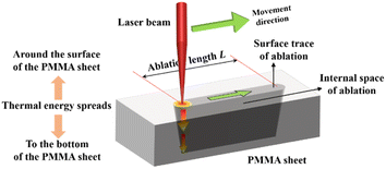
During the process of CO2 continuous laser ablation of PMMA sheets, the sheets were fixed on the operating table, and the laser could move on the XY plane, which had a linear velocity of movement. Due to the Gaussian distribution of incident laser energy,10–12 the laser energy density corresponding to the continuous laser action on various points on the surface of PMMA material is different. Unlike pulsed lasers that only release laser energy within a single pulse width, CO2 continuous lasers have continuous laser energy during the process of ablation of PMMA materials.13,14 The velocity of laser beam translation directly affects the amount of energy absorbed by a certain ablation point on the surface of the material, and ultimately affects the ablation threshold of PMMA materials. Therefore, for the temperature field simulation of CO2 continuous laser ablation of PMMA sheets, it was necessary to modify the heat source term to a filamentous Gaussian heat source, as shown in Fig. 1.The energy of a CO2 continuous laser beam exhibits a Gaussian distribution in both time and space, and the laser energy density is higher in the center of the laser beam and gradually decreases along the Gaussian contour as the laser beam radius increases.15–17 If the ablation distance of the continuous laser on the PMMA sheet was set to L, its linear velocity of movement was v, and the diffusion and transfer distance of thermal energy on the ablation surface of the sheet could be regarded as infinite. Therefore, the thermal energy absorbed by the sheet surface was equal to the total heat output by the laser under this condition. It can be inferred that the expression for the laser energy density of CO2 continuous laser beam is: (see Appendix A)
 | (1) |
2.2 Heat transfer physical model
Considering the interaction process between CO2 continuous laser and PMMA material, based on the Fourier heat transfer basic model,18–20 a filamentous Gaussian heat source term was introduced, and the influence of laser beam horizontal displacement line velocity was considered to establish a heat transfer physical model for CO2 continuous laser ablation of PMMA material. The initial condition was set to approximately 300 K at room temperature, the heat energy transmission at the surface of PMMA plate was the absorption of laser energy by the material surface, and there was no further heat energy transmission at the maximum ablation depth of the sheet.21–23 The finite-difference time-domain method was used to study the heat transfer physical model and boundary conditions,24,25 and establishing a grid Fourier number, the heat transfer physical model of CO2 continuous laser ablation of PMMA material was established as follows:26,27 (see Appendix A)
 | (2) |
2.3 Numerical simulation and analysis
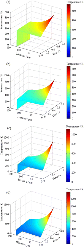
The mentioned above heat transfer difference eqn (2) was used to perform numerical simulation. Combined with the thermophysical parameters of PMMA material (Table 1) and related calculation parameters (Table 1), the temperature evolution law of CO2 continuous laser ablation of PMMA material could be obtained by setting the laser beam movement velocity to 90 mm s−1 and keeping it constant, and the laser power to 20 W, 40 W, 60 W, and 80 W, respectively, as shown in Fig. 2.| Parameter content | Name | Symbol/unit | Numerical value | Name | Symbol/unit | Numerical value |
|---|---|---|---|---|---|---|
| Thermophysical parameters of the PMMA | Atomic mass | m/kg | 1.661 × 10⁻²⁵ | Specific heat capacity | λ/(J kg−1 K−1) | 1420 |
| Density | ρs/(kg m−3) | 1180 | Melting temperature | Tm/K | 403.15–413.5 | |
| Thermal conductivity | ks/(W m−1 K−1) | 0.189 | Gasification temperature | Tv/K | 543.15 | |
| Thermal diffusivity | γ/(m2 s−1) | 11 × 108 | Absorption coefficient | b | 0.92 | |
| Calculation parameters | Laser wavelength | λ/nm | 1064 | Spot diameter | D/μm | 562 |
| Electron mass | me/kg | 9.1 × 10⁻³¹ | Laser output power | P/W | 100 | |
| Table stroke | l/mm | 1300 × 900 | Lighting time | t/s−1 | 0.5 | |
| Atmospheric pressure | — | 50% | Lighting mode | — | Spotting/ablation |
The temperature change of CO2 continuous laser ablation of PMMA material is shown in Fig. 2(a). When the laser beam moved at velocity of 90 mm s−1 and the laser power reached 20 W, the maximum temperature of PMMA material was approximately 520 K, which was higher than the melting temperature of PMMA material (413.5 K), but could not reach the gasification temperature (543.15 K). It indicated that when the laser was at a low power of 20 W, the PMMA sheet in the ablation area could be locally melted, enabling it to complete the transition from solid to liquid phase, and producing ablation effect on the material surface. Fig. 2(b) and (c) show that when the laser power was gradually increased to 40 W and 60 W, and the moving velocity of the laser beam was kept constant at 90 mm s−1, the surface temperature of PMMA sheet was approximately 815 K and 1080 K, respectively, which were much higher than the gasification temperature at this time. These results showed that under this laser power, CO2 continuous laser could vaporize PMMA material, cracked the polymer structure of polymethyl methacrylate, so as to separate from the surface of the plate, and achieved the ablation effect. Fig. 2(d) shows that when the laser beam moved at velocity of 90 mm s−1 and the laser power reached 80 W, the maximum surface temperature of PMMA sheet was approximately 1300 K. Under this process condition, the CO2 continuous laser ablation of PMMA sheet had the highest processing efficiency. Moreover, due to the high laser beam movement velocity, the surface effect of PMMA sheet was the smallest due to the thermal accumulation effect of the laser beam and the CO2 continuous laser ablation effect was the best.
3 Experimental equipment and methods
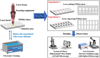
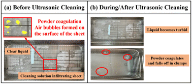
Fig. 3 shows the experiment process flow chart of CO2 continuous laser ablation PMMA material. The size of the PMMA sheet in the experiment was: 200 mm (long) × 150 mm (width) × 2 mm (thick). The average laser output power was 10–100 W, the scanning velocity was 0–100 mm s−1, and the laser wavelength was 1064 nm. Fig. 3 showed that the high-energy laser beam was focused by the internal lens of the laser ablation head and then vertically incident to the surface of PMMA sheet, PMMA sheet was fixed on the operating machine, the program was set to scan and move the laser on the two-dimensional moving plane of the X and Y axes to complete the pitting and engraving operations. During the ablation process, the laser system was equipped with an air extraction device to discharge the generated toxic gas to prevent environmental pollution.After ultrasonic cleaning of PMMA sheets after CO2 continuous laser ablation, the impurity particles attached to the pit surface of PMMA sheets by laser falled off and entered the water, making the liquid turbid. The cleaning effect is shown in Fig. 4. After the dirt on the surface of the board was thoroughly removed, it was dried to ensure that there were no water stains on the surface. Finally, low-pressure mercury/sodium lamp with optical microscope and system of three-dimensional ultra-depth-of-field were used to observe the topographic and geomorphic characteristics of PMMA material surface after CO2 continuous laser ablation, and the data such as pit diameter and depth were obtained by computer.
4 Results and discussion
4.1 Change evolution law of small hole diameter with defocusing amount
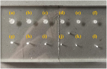
The laser parameter settings for continuous laser processing of PMMA sheets are shown in Table 2. Based on the regulation of the upper scale of the Z-axis focusing device of the laser ablation head, the starting point was the “1.6 cm” of the middle scale of the focusing device. The defocusing amount was 16 mm, and the distance between each movement was 2 mm. Repeat the experiment 12 times to cover three situations: positive defocus, zero defocus, and negative defocus. The CO2 continuous laser spotting operation on PMMA sheets was completed under different parameters, with light output time of 0.5 s. Based on the experimental parameters in Table 2, the PMMA sheet after CO2 continuous laser irradiation is shown in Fig. 5.| Name | Numerical values |
|---|---|
| Laser wavelength λ/nm | 1064 |
| Laser power P/W | 100 |
| Workbench stroke l/mm | 1300 × 900 |
| Light output time t/s | 0.5 |
| Air pressure | 50% |
| Luminous mode | Spotting |
The topography of surface of PMMA sheets after ablation were observed by the system of three-dimensional ultra-depth-of-field (×50 times), and the diameter of the small hole on the surface of PMMA sheets was measured with defocusing amounts of 12 mm, 10 mm, 8 mm, 6 mm, 4 mm, 2 mm, 0 mm, −2 mm, and −4 mm, respectively.
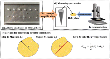
Due to the influence of equipment processing accuracy, the laser equipment did not engrave a regular circular shape on the PMMA sheets, as shown in Fig. 5. Therefore, selecting the diameter in any direction of the ablation circular hole cannot effectively represent the aperture size. In order to ensure the accuracy of data measurement and reduce aperture measurement errors, it is necessary to measure multiple sets of data to obtain an average value to represent the size of the surface diameter of the ablation hole. Based on the above considerations, the scale d1 of the engraving hole aperture from the top left direction to the bottom right direction, and the scale d2 from the bottom left direction to the top right direction were selected to measure, as shown in Fig. 6.
The PMMA sheet after continuous laser ablation was placed on the observation platform of the three-dimensional ultra deep microscopy system, and the ablation holes were adjusted to be placed in the center of the field of view. The three-dimensional ultrasound microscopy system could take photos of them and display them through a computer. After determining the endpoints to be measured for d1 and d2, the surface diameter of each ablation pit could be read from the computer and display the scale. The specific data is shown in Table 3.
| Defocusing amount x/mm | Diameter d1/μm | Diameter d2/μm |
|---|---|---|
| 12 | 2013 ± 201 | 1948 ± 195 |
| 10 | 1857 ± 186 | 1950 ± 195 |
| 8 | 1744 ± 174 | 1704 ± 170 |
| 6 | 1667 ± 167 | 1615 ± 162 |
| 4 | 1351 ± 135 | 1399 ± 140 |
| 2 | 1140 ± 114 | 1111 ± 111 |
| 0 | 1066 ± 107 | 1024 ± 102 |
| −2 | 1154 ± 115 | 1157 ± 116 |
| −4 | 1667 ± 167 | 1544 ± 154 |
The average diameter of the approximate circle of the small hole was obtained from eqn (3):
 | (3) |
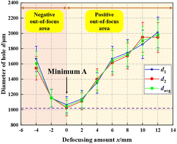
Through calculation, the numerical results were as follows: 1980 ± 198 μm, 1903 ± 190 μm, 1724 ± 172 μm, 1641 ± 164 μm, 1375 ± 138 μm, 1125 ± 113 μm, 1045 ± 105 μm, 1155 ± 116 μm and 1606 ± 161 μm, respectively. The error was approximately 10%, mainly caused by experimental instrument error, environmental error, and measurement error. The variation law of the average diameter of small holes with defocusing amount is shown in Fig. 7, and the vertical axis represents the aperture, in units of μm, and the horizontal axis represents the defocusing amount, in units of mm.
From the evolution law of the average diameter (davg) of the small hole with the defocusing amount, it could be seen that when the defocusing amount gradually decreased from 12 mm to 2 mm, that is when the defocus position changed from positive to zero, the diameter reduced from 1980 μm to 1125 μm. When the defocusing amount decreased to 0 mm, the diameter was the smallest, approximately 1045 μm. It could be approximated as the diameter of the laser beam focal spot. In the negative out-of-focus area, as the defocusing amount increased from zero defocus position to 4 mm, the diameter increased again from 1155 μm to 1606 μm. Considering the calculation formula for laser power density:
 | (4) |
In the formula, I0 is the power density of CO2 continuous laser, W mm−2; P is the laser power, W; d is the diameter of the laser spot, mm. When the laser power was 100 W and the laser spot diameter were 1980 ± 198 μm, 1903 ± 190 μm, 1724 ± 172 μm, 1641 ± 164 μm, 1375 ± 138 μm, 1125 ± 113 μm, 1045 ± 105 μm, 1155 ± 116 μm and 1606 ± 161 μm, the corresponding laser power density values were shown in Table 4.
| Defocusing amount (x)/mm | Diameter of the laser spot (d)/μm | Laser power density (I0)/(W mm−2) |
|---|---|---|
| a The laser power is all 100 W. | ||
| 12 | 1980 | 32.5 |
| 10 | 1903 | 35.1 |
| 8 | 1724 | 42.8 |
| 6 | 1641 | 47.2 |
| 4 | 1375 | 67.3 |
| 2 | 1125 | 100.4 |
| 0 | 1045 | 116.5 |
| −2 | 1155 | 95.3 |
| −4 | 1606 | 49.3 |
From Table 4, it could be seen that as the diameter of the laser spot (d) decreased from 1980 μm to 1125 μm, the laser power density (I0) gradually increased from 32.5 W mm−2 to 100.4 W mm−2, and the maximum laser power density (I0max) was obtained at the minimum spot diameter of 1045 μm, with a value of 116.5 W mm−2. When the diameter of the laser spot increased to 1606 μm, the laser power density decreased to 49.3 W mm−2. Therefore, when the laser power is constant, the laser power density is inversely proportional to the diameter of the laser spot, and the maximum laser power density can be obtained when the diameter of the laser spot is the smallest. In summary, in order to improve laser energy utilization and processing efficiency and avoid laser energy waste, the minimum laser spot should be selected, which is the diameter of the laser beam focal spot (approximately 1045 μm). At this point, the Z-axis adjustment distance was 3.2 cm.
4.2 Change evolution law of hole depth with defocusing amount
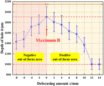
To obtain the change evolution law of hole depth with defocusing amount, the same experimental steps as shown in Section 4.1 can be performed. The CO2 continuous laser spotting operation on PMMA sheets under different parameters was completed, with a laser output time of 0.5 s. The topographic and geomorphological characteristics of the surface of PMMA sheets were observed by the system of three-dimensional ultra-depth-of-field (×50 times), and the depths of the holes were measured. The measurement error was approximately 10%, due to the fact that the acrylic plate is a transparent material and was limited by laser experimental equipment and the accuracy of the system of three-dimensional ultra-depth-of-field, resulting in instrument errors. Fig. 8(a–l) shows the surface topography of PMMA materials with defocusing amounts (x) of 14 mm, 12 mm, 10 mm, 8 mm, 6 mm, 4 mm, 2 mm, 0 mm, −2 mm, −4 mm, −6 mm, and −8 mm, respectively. In the topographic map of PMMA material surface captured under the system of three-dimensional ultra-depth-of-field, there were a certain degree of fluctuation around the holes, due to factors such as dust scattering in the air on the test sample.When the defocusing amount (x) was 14 mm, 12 mm, 10 mm, 8 mm, 6 mm, 4 mm, 2 mm, 0 mm, −2 mm, −4 mm, −6 mm, and −8 mm, respectively, the depth of the surface pits was 1000 ± 100 μm, 1003 ± 103 μm, 1372 ± 137 μm, 1577 ± 158 μm, 1636 ± 164 μm, 1758 ± 176 μm, 1807 ± 181 μm, 1908 ± 191 μm, 1766 ± 177 μm, 1719 ± 172 μm, 1479 ± 148 μm, and 1435 ± 144 μm, respectively. The variation law is shown in Fig. 9.
The hole depth of PMMA material ablate CO2 continuous laser is: H = H(d,v,P). The relationship indicates that the parameters that affect the depth of surface hole erosion of PMMA materials are laser spot diameter (d), continuous laser scanning velocity (v), and laser power (P). As shown in Fig. 9, when the laser power and laser beam scanning velocity were constant, the diameter of the laser spot gradually decreased with the decrease of defocusing amount, and the overall hole depth showed an increasing trend. When the defocusing amount (x) decreased from 14 mm to 2 mm, the depth of the small hole increased gradually from 1000 μm to 1807 μm. When the defocusing amount (x) decreased to 0 mm, the depth of the small hole reached its maximum, approximately 1908 μm. Its depth was close to the thickness of PMMA sheet, and the laser was about to penetrate the sheet. In the negative out-of-focus are, as the defocusing amount increased from zero defocus position to 8 mm, the depth of the small hole reduced again, approximately from 1766 μm to 1435 μm.
4.3 Change evolution law of PMMA material ablation quality
Based on the above experimental conclusions, in order to improve the processing accuracy of CO2 continuous laser ablation of PMMA materials and the utilization of laser energy, the Z-axis offset was selected as 3.2 cm, the defocusing amount was 0 mm, and the laser spot diameter was the smallest, approximately 1045 μm. The calculation formula for laser power density is shown in eqn (4), when the laser power of 20 W, 40 W, 60 W, 80 W, and 100 W were selected, the corresponding laser power densities were 23.3 W mm−2, 46.6 W mm−2, 69.9 W mm−2, and 93.2 W mm−2, respectively. Repetitive experiments of CO2 continuous laser ablation on PMMA sheets under corresponding parameters were carried out, as shown in experiment 2 in Fig. 3. The laser process parameters were set as shown in Table 5.| Name | Unit | Numerical value | Name | Unit | Numerical value |
|---|---|---|---|---|---|
| Laser wavelength | λ/nm | 1064 | Laser power | P/W | 20/40/60/80 |
| Defocusing amount | x/mm | 0 | Laser power density | I0/(W mm−2) | 23.3/46.6/69.9/93.2 |
| Laser beam movement velocity | v/(mm s−1) | 20/40/60/80/100 | Atmospheric pressure | — | 50% |
| Target graphic dimensions | l/mm | 70 × 28 | Light output method | — | Engraving |
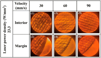 | ||
| Fig. 10 Surface morphology of PMMA sheet observed under low-pressure mercury/sodium lamp with optical microscope. | ||
Fig. 10(a)–(d) shows the surface morphology of the interior and edges of PMMA sheets corresponding to laser power density of 23.3, 46.6, 69.9, and 93.2 W mm−2 and laser beam movement velocity of 30, 60, and 90 mm s−1, respectively. As shown in Fig. 10, when the laser power density was constant, as the laser beam movement velocity increased from 30 mm s−1 to 60 mm s−1, the surface of the PMMA sheet had a smooth matte texture inside the holes, gradually improving its transparency, and the serrated phenomenon at the edges became more obvious. As the laser beam movement velocity further increased to 90 mm s−1, the surface transparency of PMMA sheets decreased again, and the internal texture of the surface gradually became clear under low-pressure mercury/sodium lamp with optical microscope. The overlap of the light path during the laser beam bidirectional engraving increased, the edge serration decreased, and the curve gradually tended to be smooth. The moving velocity of the laser beam was controlled at a certain velocity. With the increase of the laser power density from 23.3 W mm−2 to 93.2 W mm−2, the internal texture of the holes on the surface of the PMMA sheet changed from shallow to deep and then to shallow again. It could be seen that when the laser power density was small or large, the interior of the holes was relatively smooth, and the edge curve was relatively flat. When the laser power density was 46.6 W mm−2 or 69.9 W mm−2, the surface texture caused by the laser beam engraving along the optical path was obvious and rough, with strong serration at the edges.
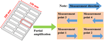
In order to explore the influence of laser process parameters on the ablation quality, a combination of different laser power and laser movement velocity was constructed. During the experiment, 12 different laser parameters were selected for combination, including three different laser power densities and four different laser beam moving velocity. The selection of these variables was based on a certain gradient and interval, and covered the entire range of laser power density and laser beam moving velocity that could be selected for continuous laser equipment as much as possible. Due to the fact that the laser used in the experiment can be moved on a three-dimensional displacement platform, the PMMA board was fixed on the operating platform. Each PMMA sheet selected in the experiment has a size of 150 mm × 200 mm. To ensure that surface roughness detection equipment can measure the surface of PMMA sheets after laser ablation and maximize the utilization of each experimental sample, our research team engraved 14 rectangular planes on a complete PMMA sheet, each of which has the same size as 70 mm × 28 mm.
The portable surface roughness measuring instrument (Model: Taylor Hobson Surtronic DUO, UK) was used to measure the surface roughness value of PMMA material after CO2 continuous laser ablation. In actual measurement, the more measurement points there are, the more accurate Ra is. Therefore, four points in each ablation area, namely bottom left, bottom right, top right, and top left, were selected as measurement points 1, 2, 3, and 4, as shown in Fig. 11. The roughness measuring instrument was placed vertically within each measuring point, with points 1 and 2 measuring from left to right, and points 3 and 4 measuring from right to left. The different surface roughness values within 4 measurement points were obtained, and then the average surface roughness value was calculated to reduce the impact of errors.
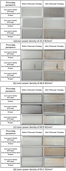
The laser power density of 23.3 W mm−2, 46.6 W mm−2, 69.9 W mm−2 and 93.2 W mm−2 and the moving velocity of the laser beam of 30 mm s−1, 60 mm s−1 and 90 mm s−1 were selected respectively for combination. Based on different process parameters, CO2 continuous laser ablation of PMMA materials was carried out. After ultrasonic cleaning and drying (see Appendix B), the surface roughness value was obtained by measuring instrument as shown in Table 6.
| Laser power density (I0)/(W mm−2) | Laser beam moving velocity (v)/(mm s−1) | Surface roughness values (Ra)/μm | ||||
|---|---|---|---|---|---|---|
| Measurement point 1 | Measurement point 2 | Measurement point 3 | Measurement point 4 | Average value | ||
| 23.3 | 90 | 4.46 | 4.29 | 4.55 | 4.65 | 4.49 |
| 46.6 | 90 | 5.00 | 2.85 | 2.78 | 4.00 | 3.66 |
| 69.9 | 90 | 6.09 | 4.47 | 3.51 | 4.90 | 4.74 |
| 93.2 | 90 | 4.25 | 3.76 | 2.41 | 3.33 | 3.43 |
As shown in Table 6, when the laser beam movement velocity was constant, the change in laser power density did not cause significant changes in surface roughness values, and their fluctuations were within the error range. By controlling the laser power density to a certain extent, the minimum surface roughness value of approximately 3.43 μm could be obtained at a laser beam movement velocity of 90 mm s−1, and the maximum value of approximately 9.27 μm could be reached at 60 mm s−1. Moreover, the change of the laser beam movement velocity could effectively reduce the surface roughness value. The surface roughness decreased by approximately 39.73%, 60.52%, 48.59%, and 62.84% for the four laser power densities corresponding to different moving velocities, respectively. The above conclusion indicated that as the moving velocity of the laser beam increased, the residence time of the laser beam at any point in the hole became shorter, resulting in less laser energy accumulation and smaller thermal effect. The evolution of surface roughness value (Ra) with laser power density and laser beam movement velocity is shown in Fig. 12.
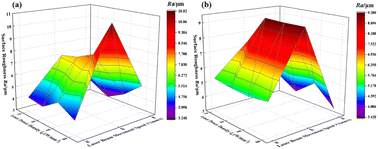 | ||
| Fig. 12 Variation law of surface roughness value (Ra) with laser power density and laser beam movement velocity. | ||
During the process of laser ablation, with the increase of incident laser energy, the temperature increased, and the influence component of pyrolytic polymerization effect increased. When the laser power density was 23.3 W mm−2, the surface of the holes was relatively smooth and the transparency was poor. The reason is that the incident laser power density was small, and the thermal depolymerization component caused by temperature was lower. When the laser power densities were 46.601 and 69.9 W mm−2, respectively, the laser energy further increased, the temperature of the processed surface increased, and the proportion of thermal depolymerization during the ablation process increased. During the pyrolysis polymerization process, the surface temperature of PMMA board was relatively high, and the decomposed methyl methacrylate monomer powder splashed, resulting in a rough machined surface with a relatively high average surface roughness (Raavg). The surface temperature of materials increased with the increase of laser energy density, and the proportion of thermal depolymerization effect in the ablation process further increased. When the laser power density was 93.2 W mm−2, the PMMA in a molten state was formed, and it solidified to form a PMMA glass body after cooling. Therefore, the surface of materials was smoother, and the average surface roughness (Raavg) decreased compared to lower laser power density.
The proportion of thermal depolymerization effect in the ablation process increased with the increase of laser power density. When the laser power density was high, PMMA materials in a molten state could be formed and condensed into PMMA glass body. Under this condition, the ablation surface roughness value of PMMA sheets was relatively small. In addition, the moving velocity of the laser beam directly affected the residence time of the laser beam on the surface of PMMA sheet, therefore affecting the size of the heat affected area. When the moving velocity of the laser beam was 60 mm s−1, the PMMA sheet was irradiated by the laser for a long time, resulting in an increase in the heat affected area of the surface, uneven laser energy absorbed by the surface, uneven material removal, resulting in surface undulation and large surface roughness. When the moving velocity of the laser beam was 90 mm s−1, the heat affected area of the PMMA sheet surface was smaller, the material surface was removed more smoothly, and the surface roughness was lower.
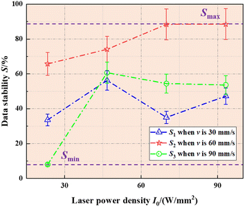
The surface roughness values of measurement point 1 and measurement point 4 under 12 different conditions were generally greater than those of measurement point 2 and measurement point 3. The reason is that when obtaining surface roughness data at measurement point 1 and measurement point 4, the roughness measuring instrument measured the roughness value of the edge of the sample hole, which is severely affected by thermal effects caused by laser action. Data stability (S) is an indicator that measures the volatility and discreteness of data. The smaller the fluctuation and dispersion of data, the higher the stability. Considering the influence of the larger edge roughness value on the overall surface roughness, the data stability (S) should be taken as the basis for judging the quality of PMMA materials ablated by CO2 continuous laser. The maximum difference method was selected as a method to measure the stability of surface roughness data, which is determined by analyzing the percentage of the maximum and minimum roughness values to the average roughness value. The calculation is simple and can visually observe the volatility of surface roughness data. The calculation formula is:
 | (5) |
In the formula, Ramax, Ramin, and Raavg are the maximum, minimum, and average surface roughness values, respectively. The calculated values are shown in Table 7, and the variation law of data stability with laser power density and laser beam movement velocity is shown in Fig. 13.
| Laser power density (I0)/(W mm−2) | Laser beam moving velocity (v)/(mm s−1) | Data stability (S)/(%) |
|---|---|---|
| 23.3 | 30 | 33.58 |
| 60 | 65.77 | |
| 90 | 8.02 | |
| 46.6 | 30 | 56.25 |
| 60 | 74.11 | |
| 90 | 60.66 | |
| 69.9 | 30 | 35.05 |
| 60 | 88.39 | |
| 90 | 54.43 | |
| 93.2 | 30 | 47.24 |
| 60 | 88.52 | |
| 90 | 53.64 |
As shown in Fig. 13, when the laser beam movement velocity (v) was 60 mm s−1, the data stability (S2) at any laser power density was greater than 60%, higher than S1 and S3. The maximum value of data stability occurred at a laser power density (I0) of 93.2 W mm−2, which was approximately 88.52%. When the laser power density (I0) was 23.3 W mm−2 and the laser beam movement velocity (v) was 90 mm s−1, the minimum data stability value of 8.02% was obtained, which had the optimal data stability, minimal data fluctuation and dispersion. Under the composite pattern of laser process parameters, the surface of the engraved PMMA sheet had little fluctuation and relatively stable, and flat terrain could be obtained.
4.4 Application of laser processing technology
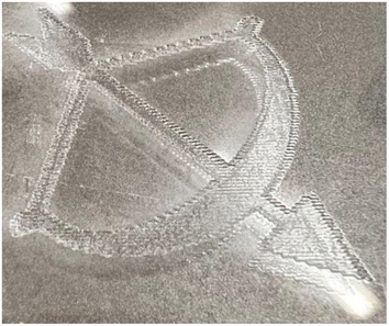
Based on the above change evolution law of diameter and depth of the hole with defocusing amount, it is found that in the process of CO2 continuous laser processing of PMMA materials, adjusting the defocusing amount to 0 mm can ensure the utilization of laser energy, minimize the cutting seam, and improve the shape accuracy of PMMA materials. Based on the change evolution law of PMMA material ablation quality, when the laser power density of 23.3 W mm−2 and the laser movement velocity of 90 mm s−1 were selected, the CO2 continuous laser processing of PMMA material ablation quality was ideal. Fig. 14 shows the PMMA material process sample processed by using this laser process parameter combination. As shown in Fig. 14, the concave surface of PMMA material fluctuates stably and the roughness was not high. Ablating PMMA material in this composite pattern of laser process parameters could obtain the most ideal laser processing.5 Conclusion
In the paper, the physical process of CO2 continuous laser ablation of Polymeric Methyl Methacrylate materials from both theoretical and experimental perspectives, and the factors that affect the quality of laser processing were analyzed. The specific conclusions were as follows:(1) based on the theoretical model and simulation analysis, it could be concluded that under the condition of a constant laser beam movement speed of 90 mm s−1, when the laser power was 20 W, the transformation of PMMA materials from solid to liquid phase in the laser ablation area was achieved. When the laser power was 40 W, the polymer structure of polymethyl methacrylate would be cracked. When the laser power was 80 W, its processing efficiency was the highest. The theoretical analysis was consistent with actual physical processes.
(2) Experimental researches showed that during the process of selecting a 100 W CO2 continuous laser ablation of PMMA materials, irregular conical small holes were generated on the surface. The diameter and depth of the holes showed a pattern of first decreasing and then increasing, and first increasing and then decreasing with the decrease of the defocusing amount, respectively. When the defocusing amount of the laser beam was 0 mm, the minimum diameter and the deepest apertures could be generated on the surface of PMMA material, with values of approximately 1045 μm and 1908 μm, respectively.
(3) After determining the size of the laser spot, it could be seen that when the laser power density of 23.3 W mm−2 and the laser movement velocity of 90 mm s−1 were selected, the CO2 continuous laser processing of PMMA material ablation quality was ideal, which had a smaller surface roughness and the best data stability, approximately 4.49 μm and 8.02%, respectively.
Author contributions
Song Cai – conceptualization, methodology, software, writing—review and editing, funding acquisition. Wenhao Liu – software, validation, visualization, writing—original draft preparation. Da Chen – formal analysis. Fan Yu – investigation. Nengru Tao – resources, data curation. Junfeng Man – supervision, project administration, funding acquisition. All authors have read and agreed to the published version of the manuscript.Conflicts of interest
There are no conflicts to declare.Appendices
Appendix A
The derivation process of heat transfer physical model for carbon dioxide continuous laser processing of PMMA materialsIf the ablation length of a continuous laser was set to L and its linear velocity of movement was v, the time for CO2 continuous laser ablation of PMMA sheets was expressed as:
| t = L/v | (6) |
The total heat output (QZ) during laser ablation of PMMA sheets was expressed as:
 | (7) |
The energy of a CO2 continuous laser beam exhibits a Gaussian distribution in both time and space, and the laser energy density is higher in the center of the laser beam and gradually decreases along the Gaussian contour as the laser beam radius increases.14–16 The specific expression was:
 | (8) |
 | (9) |
The ablation distance of the laser beam on the PMMA sheet was L, and the diffusion and transfer distance of thermal energy on the ablation surface of the plate could be regarded as infinite. Therefore, when the laser beam performed L-length ablation on the PMMA sheet, the thermal energy absorbed by the plate surface was equal to the total heat output by the laser. It could be expressed as:
 | (10) |
 | (11) |
 | (12) |
 | (13) |
 | (14) |
 | (15) |
 | (16) |
 | (17) |
 | (18) |
By substituting the peak expression qm (17) into eqn (9), we can obtain:
 | (19) |
In the process of CO2 continuous laser ablation of PMMA sheets, a filamentous Gaussian heat source term was introduced, and the influence of the linear velocity of laser beam translation was considered. Based on the coupled Fourier heat transfer basic model, a physical heat transfer model for CO2 continuous laser ablation of PMMA sheets was established as follows:17–19
 | (20) |
In the formula, b is the absorption rate of PMMA sheet; L is the distance between the incident laser and the surface of PMMA sheet.
The Initial condition was set to approximately 300 K at room temperature, the heat energy transmission at the surface of PMMA plate was the absorption of laser energy by the material surface, and there was no further heat energy transmission at the maximum ablation depth of the plate.20–22 The initial condition and the boundary conditions were established as follows:
| T(l,t) = T0, t = 0 | (21) |
 | (22) |
 | (23) |
The finite-difference time-domain method is a numerical method for solving differential equations, which can be used to solve ordinary differential equation and partial differential eqn (24) and (25). Therefore, the finite difference equations for the heat transfer physical model (20) and boundary conditions (17)–(19) were established as follows:
 | (24) |
 | (25) |
| Tdj = 0 | (26) |
| Ti0 = 300 K | (27) |
After organizing eqn (24), we could obtain:
 | (28) |
After establishing the grid Fourier number  , eqn (28) could be transformed into the following form:25,26
 | (29) |
Appendix B
(a) Laser power density of 23.3 W mm−2
(b) Laser power density of 46.6 W mm−2
(c) Laser power density of 69.9 W mm−2
(d) Laser power density of 93.2 W mm−2 (Fig. 15).
Appendix C
(b) Laser power density of 46.6 W mm−2
(c) Laser power density of 69.9 W mm−2
(d) Laser power density of 93.2 W mm−2 (Fig. 16 and Table 8).
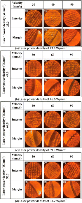 | ||
| Fig. 16 Surface morphology of PMMA sheet observed under low-pressure mercury/sodium lamp with optical microscope. | ||
| Laser power density (I0)/(W mm−2) | Laser beam moving velocity (v)/(mm s−1) | Surface roughness values (Ra)/μm | ||||
|---|---|---|---|---|---|---|
| Measurement point 1 | Measurement point 2 | Measurement point 3 | Measurement point 4 | Average value | ||
| 23.3 | 30 | 5.79 | 5.22 | 4.21 | 5.99 | 5.30 |
| 60 | 9.89 | 5.02 | 4.99 | 9.89 | 7.45 | |
| 90 | 4.46 | 4.29 | 4.55 | 4.65 | 4.49 | |
| 46.6 | 30 | 5.98 | 3.74 | 4.16 | 6.62 | 5.12 |
| 60 | 12.41 | 5.54 | 9.82 | 9.33 | 9.27 | |
| 90 | 5.00 | 2.85 | 2.78 | 4.00 | 3.66 | |
| 69.9 | 30 | 5.98 | 4.21 | 4.34 | 5.67 | 5.05 |
| 60 | 11.44 | 8.33 | 4.48 | 12.63 | 9.22 | |
| 90 | 6.09 | 4.47 | 3.51 | 4.90 | 4.74 | |
| 93.2 | 30 | 5.84 | 4.80 | 3.95 | 6.43 | 5.25 |
| 60 | 12.05 | 6.59 | 5.06 | 13.23 | 9.23 | |
| 90 | 4.25 | 3.76 | 2.41 | 3.33 | 3.43 | |
Acknowledgements
This research was funded by the National Natural Science Foundation for Young Scientists of China (Grant No. 51705141); the Guangxi Natural Science Foundation (Grant No. 2023JJA160071); the Research Foundation of Education Bureau of Hunan Province, China (Grant No. 21B0523); the China Postdoctoral Science Foundation (Grant No. 2019T120650, 2018M632835); the Key Technologies for Intelligent Monitoring and Analysis of Equipment Health Status of Science and Technology Innovation Team in College of Hunan Province (Grant No. 2023-233); and the Excellent Young and Middle-aged Scientific and Technological Innovation Team of Colleges and Universities in Hubei Province (Grant No. T2020042).Notes and references
- A. Elia, J. Deering, A. Clifford, B. Lee, K. Grandfield and I. Zhitomirsky, Electrophoretic deposition of polymethylmethacrylate and composites for biomedical applications, Colloids Surf., B, 2020, 110763 CrossRef PubMed
.
- N. K. Fahad and R. S. Sabry, Study of some mechanical and physical properties of PMMA reinforced with (TiO2 and TiO2-GO) nanocomposite for denture bases, J. Polym. Res., 2022, 29(10), 439 CrossRef CAS
.
- L. J. Li, Y. B. Zhang, L. Y. Sun and H. P. Hu, Effects of strain rate and temperature on the mechanical behavior of polymethyl methacrylate (PMMA), Polym. Bull., 2020, 80(8), 8685–8702 CrossRef
.
- C. Jobey, N. Allanic, P. Mousseau and R. Deterre, Prediction of thickness distribution of thermoformed multilayer ABS/PMMA sheets, Proceedings of The 19th International Esaform Conference on Material Forming (Esaform 2016), 2017, vol. 1769, p. 170033 Search PubMed
.
- X. H. Hu, X. Chen, R. Min, H. Qu, C. Caucheteur and H. Y. Tam, Femtosecond laser point-by-point Bragg grating inscription in BDK-doped step-index PMMA optical fibers, Opt. Lett., 2022, 47(14), 3547 CrossRef PubMed
.
- L. M. Amirabad, M. Tahriri, P. Zarrintaj, R. Ghaffari and L. Tayebi, Preparation and characterization of TiO2-coated polymerization of methyl methacrylate (PMMA) for biomedical applications: in vitro study, Asia-Pac. J. Chem. Eng., 2022, 17(3), e2761 CrossRef CAS PubMed
.
- S. Dudala, L. T. Rao, S. K. Dubey, A. Javed and S. Goel, Experimental characterization to fabricate CO2 laser ablated PMMA microchannel with homogeneous surface, Mater. Today: Proc., 2020, 28(2), 804–807 CAS
.
- S. Prakash and S. Kumar, Determining the suitable CO2 laser based technique for microchannel fabrication on PMMA, Opt. Laser Technol., 2021, 139, 107017 CrossRef CAS
.
- T. T. Wang, Y. L. Wang, C. P. Chen and H. H. Zhu, Relationships between the characteristics of porosity, melt pool and process parameters in laser powder bed fusion Al-Zn alloy, J. Manuf. Process., 2021, 68, 1236–1244 CrossRef
.
- I. P. Tsygvintsev, I. V. Romanov and V. L. Paperny, Elongated long-lived jet of dense plasma produced by a hollow laser beam, Phys. Plasmas, 2021, 28(2), 023104 CrossRef CAS
.
- S. A. Romashevskiy, S. I. Ashitkov, A. V. Ovhinnikov, P. S. Kondratenko and M. B. Agranat, Formation of periodic mesoscale structures arranged in a circular symmetry at the silicon surface exposed to radiation of a single femtosecond laser pulse, Appl. Surf. Sci., 2016, 374, 12–18 CrossRef CAS
.
- S. X. Li, F. Xia and W. J. Kong, Experimental and theoretical investigation on Q-switched Nd:LuLiF4 laser, Optik, 2019, 182, 974–979 CrossRef CAS
.
- L. Ma, X. W. Kong, J. J. Liang, J. G. LiI, C. Sun, Z. B. Jin and Z. D. Jiao, Thermal and Mechanical Variation Analysis on Multi-Layer Thin Wall during Continuous Laser Deposition, Continuous Pulsed Laser Deposition, and Interval Pulsed Laser Deposition, Materials, 2022, 15(15), 5157 CrossRef CAS PubMed
.
- Y. C. Sha, Z. W. Li, Z. C. Jia, B. Han and X. W. Ni, Comparison of 20-to 1000-Hz pulsed laser and continuous laser ablation of single-crystal germanium wafers, Opt. Eng., 2023, 62(3), 036109 CAS
.
- M. H. Yang, G. Y. Wu, X. W. Li, S. Y. Zhang, H. H. Wang and J. K. Huang, Influence of heat source model on the behavior of laser cladding pool, J. Laser Appl., 2023, 35(2), 022006 CrossRef CAS
.
- S. Cai, W. H. Liu, J. C. Song, K. Deng and Y. H. Tang, Research and Progress on Truing and Sharpening Process of Diamond Abrasive Grinding Tools, Appl. Sci., 2022, 12, 4683 CrossRef CAS
.
- Z. B. Luo and Y. Y. Zhao, Numerical simulation of part-level temperature fields during selective laser melting of stainless steel 316L, Int. J. Adv. Manuf. Technol., 2019, 104(5–8), 1615–1635 CrossRef
.
- A. Khosravirad and M. B. Ayani, Comparative analysis of thermal damage to laser-irradiated breast tumor based on Fourier conduction and non-Fourier heat conduction models: A numerical study, Int. Commun. Heat Mass Transfer, 2023, 145, 106837 CrossRef
.
- Y. Q. Li, Y. Ou, J. J. Wu and Y. Zhang, Dynamic simulation on laser-metal interaction in laser ablation propulsion considering moving interface, finite thermal wave transfer, and phase explosion, Acta Astronautica, 2023, 208, 27–35 CrossRef
.
- B. Partovi, H. Ahmadikia and M. Mosharaf-dehkordi, Analytical and numerical analysis of the dual-pulse lag heat transfer in a three-dimensional tissue subjected to a moving multi-point laser beam, J. Therm. Biol., 2023, 112, 103431 CrossRef PubMed
.
- W. Z. Yang, A. Pourasghar, Y. Cui, L. Q. Wang and Z. T. Chen, Transient heat transfer analysis of a cracked strip irradiated by ultrafast Gaussian laser beam using dual-phase-lag theory, Int. J. Heat Mass Transfer, 2023, 203, 123771 CrossRef CAS
.
- A. A. Orekhov, L. N. Rabinskiy and G. V. Fedotenkov, Analytical Model of Heating an Isotropic Half-Space by a Moving Laser Source with a Gaussian Distribution, Lobachevskii J. Math., 2022, 14(4), 650 Search PubMed
.
- S. Cai, G. Y. Chen and C. Zhou, Research and application of surface heat treatment for multipulse laser ablation of materials, Appl. Surf. Sci., 2015, 355, 461–472 CrossRef CAS
.
- R. Cabrer, L. Galardo and C. Flores, Implicit finite-difference time-domain schemes for TDEM modeling in three dimensions, Geophysics, 2023, 87(5), E347–E358 CrossRef
.
- P. W. Li, J. K. Grabski, C. M. Fan and F. J. Wang, A space-time generalized finite difference method for solving unsteady double-diffusive natural convection in fluid-saturated porous media, Eng Anal Bound Elem., 2022, 142, 138–152 CrossRef
.
- C. Lohmann, J. Duennebacke and S. Turek, Fourier analysis of a time-simultaneous two-grid algorithm using a damped Jacobi waveform relaxation smoother for the one-dimensional heat equation, J. Numer. Math., 2022, 30(3), 173–207 CrossRef
.
- S. Shafie, B. RahmaniI, A. Moosaie and H. Panahi-Kalus, Distributed control of nonlinear conductivity heat transfer equation in a thick functionally graded plate, Int. Commun. Heat Mass Transfer, 2021, 130, 105786 CrossRef
.
- C. Z. Yan, L. K. Njaramba, A. M. Nzioka, B. O. Alunda, M. G. Kim, Y. J. Sim and Y. J. Kim, Assessment of carbon fibers recovered from lab-scale versus pilot-scale mechanochemical CFRP depolymerization process based on fastrack thermal oxidation-resistance characteristics, Carbon Lett., 2022, 32(4), 1085–1099 CrossRef
.
- G. Ozsin, Assessing thermal behaviours of cellulose and poly (methyl methacrylate) during co-pyrolysis based on an unified thermoanalytical study, Bioresour. Technol., 2020, 300, 122700 CrossRef CAS PubMed
.
- A. Biery and D. Knauss, Synthesis and Characterization of Copolymers from Diallyldimethylammonium Hexafluorophosphate and Methyl Methacrylate, Macromolecules, 2023, 56(4), 1572–1580 CrossRef CAS
.
Footnotes |
| † Electronic supplementary information (ESI) available. See DOI: https://doi.org/10.1039/d3ra05391a |
| ‡ The first two authors contributed equally to this work. |
| This journal is © The Royal Society of Chemistry 2024 |

