 Open Access Article
Elucidating the redox activity of cobalt-1,2,3,4-cyclopentane-tetracarboxylic acid and 1,2,4,5-benzene-tetracarboxylic acid-based metal–organic frameworks for a hybrid supercapacitor
Muhammad Zahir Iqbal *a,
Ayesha Zakira,
Misbah Shaheena,
Asma Khizara,
Kareem Yusufb,
Muhammad Javaid Iqbalc,
Zubair Ahmad*d and
Shahzad Sharif
 e
e
aRenewable Energy Research Laboratory, Faculty of Engineering Sciences, Ghulam Ishaq Khan Institute of Engineering Sciences and Technology, Topi, 23640, Khyber Pakhtunkhwa, Pakistan. E-mail: zahir@giki.edu.pk
bDepartment of Chemistry, College of Science, King Saud University, Riyadh 11451, Saudi Arabia
cCentre of Excellence in Solid State Physics, University of the Punjab, Quaid-e-Azam Campus, Lahore-54590, Pakistan
dSchool of Chemical Engineering, Yeungnam University, 280 Daehak-ro, Gyeongsan, Gyeongbuk 38541, Republic of Korea. E-mail: zubair7157@yu.ac.kr
eDepartment of Chemistry, Materials Chemistry Laboratory, Govt. College University, 54000, Lahore, Pakistan
First published on 5th January 2024
Abstract
The development of electrode materials with extraordinary energy densities or high power densities has experienced a spectacular upsurge because of significant advances in energy storage technology. In recent years, the family of metal–organic frameworks (MOFs) has become an essential contender for electrode materials. Herein, two cobalt-based MOFs are synthesized with distinct linkers named 1,2,4,5-benzene-tetra-carboxylic acid (BTCA) and 1,2,3,4-cyclopentane-tetracarboxylic acid (CPTC). Investigations have been rigorously conducted to fully understand the effect of linkers on the electrochemical properties of Co-based MOFs. The best sample among the MOFs was used with activated carbon to create a battery–supercapacitor hybrid device. Due to its noteworthy results, specific capacity (100.3 C g−1), energy density (23 W h kg−1), power density (3400 W kg−1) and with the lowest ESR value of 0.4 Ω as well as its 95.4% capacity retention, the fabricated hybrid device was discovered to be very appealing for applications demanding energy storage. An approach for evaluating battery–supercapacitors was employed by quantifying the capacitive and diffusive contributions using Dunn's model to reflect the bulk and surface processes occurring during charge storage. This study fills the gap between supercapacitors and batteries, as well as providing a roadmap for creating a new generation of energy storage technologies with improved features.
1. Introduction
Energy technology provides the world with limitless potential and powers an innovative society. The way we generate and use power is being completely transformed by energy storage. It closes the energy gap between inconsistent supply and steady demand by effectively absorbing and storing energy from renewable sources. This revolutionary technology paves the way for a greener and more resilient future in addition to ensuring a dependable and sustainable energy infrastructure. Batteries and supercapacitors provide a variety of options to satisfy the changing demands of contemporary energy storage systems.1 The bulk of the anode's faradaic reactions (electrochemical reactions that occur within the anode of a battery and store and release energy via electron movement) give batteries their high energy density, but high-power extraction from batteries is an arduous procedure that compromises the regular performance of the battery.2 Batteries perform better in situations requiring high energy density, whereas supercapacitors excel in power density and extended cycle life.3 Among the potential energy storage technologies that have been around for more than 50 years are supercapacitors. They offer several benefits, including rapid charge–discharge rate, green energy technology, maintenance-free long-life operation, and high power.4–7 By providing backup power sources to defend against power outages, electrochemical supercapacitors can supplement batteries or fuel cells in their role as energy storage devices. Hybrid capacitors are a well-studied area where energy density is significantly enhanced.8 Supercapacitors provide a storage mechanism based on capacitive (i.e., non-faradaic) processes formed by an electrochemical double layer at the electrode–electrolyte interface. Each mechanism has advantages that can be exploited to improve the power and energy densities of the energy storage strategy. Because of its huge capacitance at high operating voltage, a conventional symmetric supercapacitor causes problems, whereas batteries have cycle life limits. Asymmetric (hybrid) capacitors have the ability to overcome the challenges and limitations of capacitors and batteries.9The physiochemical characteristics of a material that is used to store energy have a significant impact on energy storage technologies. There is a considerable demand for investigating and developing new materials which is necessary to significantly enhance their efficiency to meet the increased demands of emerging systems, including hybrid electric vehicles, substantial industrial machinery, and portable electronics.10 The primary component of a battery or a supercapacitor, the electrode material, directly determines the electrochemical performance.11 The most common strategy for navigating the problem of minimal energy storage performance is the development of novel materials for electrodes. The scientific community is presently focusing on the development of novel electrode materials to produce upgraded supercapacitors and batteries with enhanced energy density and power density and higher capacity values.12 Through redox processes, oxides, transition-metal-based sulfides, transition-metal dichalcogenides, phosphates, metal–organic frameworks, and other compounds can produce high energy densities. Reduced graphene oxide, activated carbon, graphene, and other carbonaceous compounds offer maximum power density by quick charging and discharging on the electrode surface.13,14
Metal–organic frameworks (MOFs), a fascinating class of highly organized crystalline coordination polymers, are formed when metal ions or clusters coordinate with organic bridging ligands. MOFs, also known as porous coordination polymers, are coordination networks with organic ligands and the potential for porosity. These materials have a configurable topology, tunable chemical properties, extraordinarily high porosity, and particular surface areas, making them a hot topic in chemical research for applications such as gas storage, separation, sensing, proton conduction, and drug administration.15 The inherent benefits of both stiff inorganic materials and flexible organic materials are combined in MOFs.16 Extended infinite networks emerge because of the coordination of metal ions/clusters with ligands. MOFs have been demonstrated with novel properties like quick response and composite functions, which take into account the nanoscale pores, tunable structure and large surface area. Additionally, MOFs have proven useful in a variety of gas storage, conversion, catalysis, sensing, selective separation, energy storage and drug delivery applications.17,18 The Yaghi group conducted initial research on the MOF idea in 1995.19 In 1999, with a porosity of 60%, and sizable specific surface area of 2900 m2 g−1, they presented a typical MOF structure known as MOF-5, based on Zn.20 By identifying the suitable organic ligands and metal ions, numerous MOF variants have now been reported, each with unique structural, optical, magnetic, electrical, and catalytic properties.21 MOFs currently rely on physical and chemical characteristics and a structural variety since there are so many possible metal and ligand combinations. Because of their distinctive structures, MOFs have the potential to have extremely high Langmuir surface areas, with far greater values than that of activated carbon.22 Furthermore, stiff organic linkers (e.g., 1,4-benzenedicarboxylic acid (BDC) and 1,3,5-triformylbenzene (TFB)) allow for fine-tuning of pore sizes inside microporous structures ranging from a few angstroms to several nanometers. Numerous metal ions, organic linkers, and structural motifs offer practically unlimited combinations. By choosing the right coordination nodes and organic linkers, their architectures might be tailored to various target molecules.23
1,2,4,5-benzene-tetra-carboxylic acid (BTCA) is a versatile ligand utilized in MOFs because of its four carboxylic groups that can deprotonate, resulting in different coordination states. Because of its non-coplanar structure, transition metal ions can connect at different places via hydrogen bonding, where these connections are formed between the metal ion and the oxygen atoms of the carboxylate groups, which improves the stability of the MOF and allows for many bonding possibilities. A distinguishing property is the stable crystal structure, which is supported by aromatic stacking interactions. This ligand allows for the efficient creation of high-dimensional MOF frameworks for a variety of applications.24 Furthermore, due to steric hindrance, some carboxylic groups cannot be in the same plane as the phenyl ring, which allows them to link metal ions in various orientations.25 In contrast, 1,2,3,4-cyclopentane tetracarboxylic acid (CPTC) has a special molecular structure with four carboxylic groups and possesses a variety of coordination modes and richer stereoisomers with 10 different conformations. There has only ever been one known coordination polymer using the stereochemistry of CPTC.26 Additionally, the aromatic chain of CPTC offers several transition metal ion attachment sites, providing a variety of choices for chemical modification and functionalization.27 In CPTC, the crystal structure is enhanced because of the presence of aromatic rings make it suitable for its usage in MOFs due to the interactions such as π-stacking between these rings.28 Greater structural flexibility and improved electrochemical activity are made possible by the cyclopentane ring, which also increases the capacity for charge storage.
Furthermore, to gain useful knowledge about the special characteristics and future applications of these coordination polymers, research intends to clarify the synthesis, characterization, and performance of these materials. This study compared two separate MOFs containing (BTCA and CPTC) linkers with Co metal. BTCA and CPTC linkers are used due to their coordination chemistry with Co metal and ability to form stable MOFs. They create strong coordination contacts with Co ions, bind with cobalt, and improve structural integrity through pi–pi interactions, making them suitable for applications like catalysis and gas storage. The study looked at how the linkers affected the structural characteristics and electrochemical performance of Co-based MOFs. The impact of the linker on variables including charge storage capacity, charge/discharge efficiency, cycle stability, and morphology was assessed. The research advances our knowledge of the electrochemical behavior of MOFs and offers suggestions for creating MOFs with specific features for applications related to energy storage.
2. Experimental procedure
2.1 Materials
Cobalt nitrate hexahydrate, 1,2,3,4-cyclopentane tetracarboxylic acid (CPTC) linker, 1,2,4,5-benzene-tetra-carboxylic acid (BTCA), N-methyl-2-pyrrolidone (NMP), acetylene black, potassium hydroxide (KOH), AC, and polyvinylidene fluoride (PVDF) were purchased from Sigma-Aldrich in high-purity form.2.2 Synthesis of Co-based MOFs
![[thin space (1/6-em)]](https://www.rsc.org/images/entities/char_2009.gif) :
:![[thin space (1/6-em)]](https://www.rsc.org/images/entities/char_2009.gif) 50 volume ratio combination of MeOH and DMF. 145.5 mg of cobalt nitrate hexahydrate, or 0.5 mmol, was dissolved in 2 mL of a 50
50 volume ratio combination of MeOH and DMF. 145.5 mg of cobalt nitrate hexahydrate, or 0.5 mmol, was dissolved in 2 mL of a 50![[thin space (1/6-em)]](https://www.rsc.org/images/entities/char_2009.gif) :
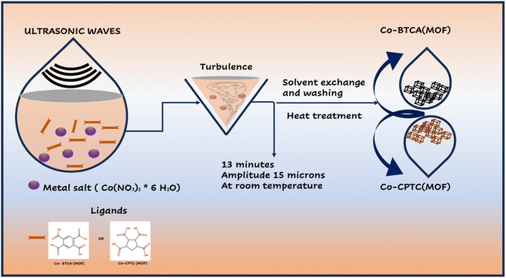
:![[thin space (1/6-em)]](https://www.rsc.org/images/entities/char_2009.gif) 50 v/v solution of meOH and DMF. The mixture of the ligand and metal salt solutions was sonicated (MSE Sanyo, Soni prep 150) for 30 minutes at a frequency of 23 kHz and an amplitude of 15 microns. As the combination cooled to normal temperature, a reddish violet powder was produced. The finished product was air dried after being cleaned with MeOH and DMF (50
50 v/v solution of meOH and DMF. The mixture of the ligand and metal salt solutions was sonicated (MSE Sanyo, Soni prep 150) for 30 minutes at a frequency of 23 kHz and an amplitude of 15 microns. As the combination cooled to normal temperature, a reddish violet powder was produced. The finished product was air dried after being cleaned with MeOH and DMF (50![[thin space (1/6-em)]](https://www.rsc.org/images/entities/char_2009.gif) :
:![[thin space (1/6-em)]](https://www.rsc.org/images/entities/char_2009.gif) 50 v/v).
50 v/v).![[thin space (1/6-em)]](https://www.rsc.org/images/entities/char_2009.gif) :
:![[thin space (1/6-em)]](https://www.rsc.org/images/entities/char_2009.gif) 50 v/v mixture of MeOH and DMF, and the pH of the dissolved ligand was set at 6.0 with 0.1 M NaOH. Cobalt chloride nitrate hexahydrate (145.5 mg, 0.5 mmol) was dissolved in 2 mL of 50
50 v/v mixture of MeOH and DMF, and the pH of the dissolved ligand was set at 6.0 with 0.1 M NaOH. Cobalt chloride nitrate hexahydrate (145.5 mg, 0.5 mmol) was dissolved in 2 mL of 50![[thin space (1/6-em)]](https://www.rsc.org/images/entities/char_2009.gif) :
:![[thin space (1/6-em)]](https://www.rsc.org/images/entities/char_2009.gif) 50 v/v MeOH and DMF. A sonicator (MSE Sanyo, Soni prep 150) was used to sonicate the combination of the ligand and metal salt solutions for 30 minutes at a frequency of 23 kHz and an amplitude of 15 microns. As the mixture cooled to normal temperature, a reddish violet powder was produced. After being air dried, the finished product was washed with MeOH and DMF (50
50 v/v MeOH and DMF. A sonicator (MSE Sanyo, Soni prep 150) was used to sonicate the combination of the ligand and metal salt solutions for 30 minutes at a frequency of 23 kHz and an amplitude of 15 microns. As the mixture cooled to normal temperature, a reddish violet powder was produced. After being air dried, the finished product was washed with MeOH and DMF (50![[thin space (1/6-em)]](https://www.rsc.org/images/entities/char_2009.gif) :
:![[thin space (1/6-em)]](https://www.rsc.org/images/entities/char_2009.gif) 50 v/v). Syntheses of Co-BTCA(MOF) and Co-CPTC(MOF) are illustrated in Fig. 1.
50 v/v). Syntheses of Co-BTCA(MOF) and Co-CPTC(MOF) are illustrated in Fig. 1.
2.3 Fabrication of the electrode material
Because of high conductivity and its porous structure, for collecting current, nickel foam was used. It was dried at 60 °C in an oven after being rinsed with ethanol, DI water and 3 M HCl, and before being used for the manufacture of the electrodes. After that, a slurry composed of 80% active material (4 mg), 5% N-methyl-2-pyrrolidone (NMP) solvent, 10% acetylene black, and 10% binder (PVDF) was applied to the nickel foam and allowed to heat in an oven for five hours at 60 °C. The same process was used to produce the electrodes for experiments using three-cell and two-cell assemblies, for electrode fabrication, slurry was deposited on each electrode, but the mass balance was considered when manufacturing a device.2.4 Characterization
The electrochemical characteristics and structural features of the synthesized Co-CPTC(MOF) and Co-BTCA(MOF) went through several characterizations. X-ray diffraction (XRD) and scanning electron microscopy (SEM) were used to examine the physical characteristics of these MOFs. Cyclic voltammetry (CV), galvanostatic charging and discharging (GCD), electrochemical impedance spectroscopy (EIS), and theoretical fitting approaches were all used to evaluate these MOFs electrochemically by utilizing a GAMRY Reference 3000 Potentiostat/Galvanostat. The performance of the synthesized MOFs was evaluated after they had gone through three-electrode assembly testing and fabrication with activated carbon in their battery–supercapacitor hybrid devices. All the tests were completed in 1 M KOH using Hg/HgO as a reference electrode, and a platinum-based counter electrode.3. Outcomes and analysis
3.1 Structural and morphological results
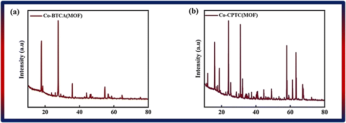
By using XRD and SEM, the structural and morphological characteristics of Co-CPTC(MOF) and Co-BTCA(MOF) were characterized. The data related to XRD is depicted in Fig. 2a and b, which demonstrated that the structure of the 1,2,3,4-cyclopentane tetracarboxylic acid MOF is based on a three-dimensional framework made up of a cyclopentane ring and four carboxylic acid groups. Co-BTCA(MOF), on the other hand, is built on a benzene ring with four carboxylic acid groups attached, creating a distinct three-dimensional framework. The distinctive ring systems used in each MOF give rise to these structural variances, which change how the carboxylic acid groups are connected to one another. The observed peaks are at angles of 15°, 18.7°, 24°, 25.3°, 30°, 32.1°, 44.5°, 49°, 57°, 61°, 63° and 67° in the XRD patterns of Co-based MOFs with 1,2,3,4-cyclopentane tetracarboxylic acid and Co-BTCA(MOF) linkers at 18°, 27°, 35.8°, 44°, 54.7°, 56.6°, 64.7°. To characterize the MOF and comprehend its possible uses, the crystal structure and quality of the MOF may be evaluated using the XRD data.3.2 Electrochemical analysis
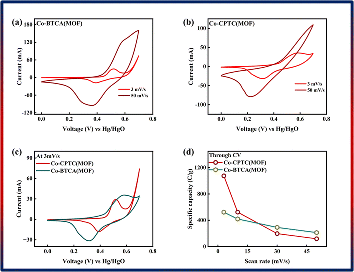 | ||
| Fig. 3 (a) Cyclic voltammetry of Co-BTCA(MOF). (b) Cyclic voltammetry of Co-CPTC(MOF). (c) Comparison of both MOF CV curves at 3 mV s−1. (d) Specific capacity through CV of both MOFs. | ||
Eqn (1) was used to calculate the specific capacities (Qs) for the cobalt-based metal–organic frameworks, which helped to confirm our assumptions.
 | (1) |
The specific capacity, integral portion, active mass placed on electrode, and scan rate are all represented in the equation above by Qs, m, and ν, respectively. A greater integrated area under the curve and greater current was shown by the CV of Co-CPTC(MOF), suggesting its better performance compared to Co-BTCA(MOF). Fig. 3d shows the plotted Qs values of Co-based MOFs (Co-BTCA(MOF) and Co-BTCA(MOF)) which are 1102 C g−1 and 682 C g−1, respectively.
The accuracy and dependability of the results of the CV analysis are strengthened by the successful validation of the collected Co-based MOF values using GCD measurements, which are illustrated in Fig. 4a and b. In the CV curves for both Co-MOFs, the redox peaks seen were represented by non-linear curves with distinct humps in the GCD curves.
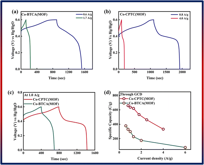 | ||
| Fig. 4 GCD of (a) Co-BTCA(MOF) and (b) Co-CPTC(MOF). (c) Comparison of both MOF GCD curves at 1.0 A g−1. (d) Specific capacity through GCD of both MOFs. | ||
Using GCD results, specific capacities were further determined by using eqn (2) to support our findings.
 | (2) |
Notably, in Fig. 4c, Co-CPTC(MOF) showed a longer discharge duration compared at 1.0 A g−1 for both MOFs, demonstrating better electrode performance. Specific capacities were computed using the GCD data at various current densities to give additional validation. Fig. 4d displays the trend in specific capacity of the Co-based MOFs with current densities and demonstrates that 1,2,3,4-cyclopentane tetracarboxylic acid possessed a high specific capacity (664 C g−1) relative to the Co-BTCA-based MOF (372 C g−1).
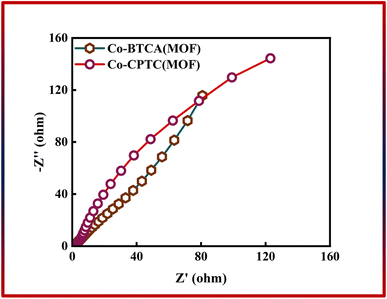
In addition to CV and GCD, EIS was used to evaluate the total conductivity of the system, which is crucial to the effectiveness of the energy storage device. Fig. 5 shows the outcomes of EIS, which shows that the Co-CPTC(MOF) and Co-BTCA(MOF) electrode-based systems have negligible charge transfer resistance (Rct) because both samples exhibit negligible resistance at the electrode surface, which indicates that at the electrode–electrolyte interface the electrochemical process is primarily controlled by faradaic processes (i.e., charge transfer reactions) rather than non-faradaic processes (e.g., double layer capacitance or diffusion). Nevertheless, low equivalent series resistance values are present in both Co-based MOFs (Co-CPTC(MOF): 0.6 Ω, Co-BTCA(MOF): 0.9 Ω).
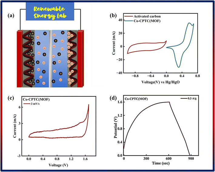
Following a successful assessment of Co-based MOFs in a three-cell assembly, Co-CPTC(MOF) demonstrated better performance and was subsequently used to create a hybrid supercapacitor. The real device was identified as Co-CPTC(MOF)//AC, consisting of a positive (Co-MOF) and a negative electrode (activated carbon), respectively. A schematic illustration of the asymmetrically manufactured Co-CPTC(MOF)//AC device is shown in Fig. 6a. To achieve efficient performance for the device, eqn (3) was used to balance the charges on both electrodes.
 | (3) |
As shown in Fig. 6b, the potential window of the device was established using independent CVs of Co-CPTC(MOF) and AC. The outcomes show the capacity of the device and its stable potential window of 0–1.7 V, underlining its tremendous potential for energy storage applications. Furthermore, the CV curve of the capacitive nature of AC is confirmed by the absence of redox peaks. The CV outcomes for the real device of Co-CPTC(MOF)//AC are shown in Fig. 6c. The curve, which include peak and an enclosed rectangular zone, demonstrate the hybrid character with both faradaic and non-faradaic processes. The CV profile illustrates how faradaic and non-faradaic responses coexist in the system. Furthermore, Fig. 6d displays the GCD data for additional corroboration of the findings. The nonlinear form of the GCD includes properties that are faradaic and non-faradaic; a little hump suggests that the form is appropriate for batteries, while a linear portion denotes capacitive behavior. The greatest achievable specific capacity from the GCD was 100.3 C g−1, demonstrating the device performance. Fig. 7a displays the trend in Qs retrieved from the GCD. Additionally, the power density and energy density values were determined using eqn (4) and (5), respectively.
 | (4) |
 | (5) |
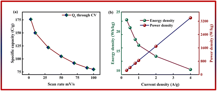 | ||
| Fig. 7 (a) Specific capacity of Co-CPTC(MOF)//AC through GCD. (b) Energy density and power density of Co-CPTC(MOF)//AC. | ||
The correlation between power and energy density can be seen in Fig. 7b. High current densities lead to an increase in power density and a drop in energy density, that causes the capacitive dominant behavior because ions have little opportunity to interact with the electrode. The highest acquired values for energy and power density are 23 W h kg−1 and 3400 W kg−1, respectively. The cyclic stability of the device is a vital consideration when assessing its performance. The cyclic stability of the device was assessed using 3000 stybility cycles while using a 4 A g−1 current density. As can be seen in Fig. 8a, the device maintained 95.4% of its initial capacity. As shown in Fig. 8b, by using both before-stability and after-stability tests of EIS, the conductivity of the device was tested. The ESR value rose from 1.3 Ω to 0.4 Ω before and after stability, showing a decrease in internal resistance following the completion of the GCD cycles. However, following a stability test, Rct seems to become insignificant, suggesting improved interaction between electrolytic ions and the electrode. Furthermore Fig. 8c presents the fitting model of the device.
 | ||
| Fig. 8 (a) Stability of Co-CPTC(MOF)//AC. (b) EIS before and after stability test. (c and d) Fitted model of EIS of Co-CPTC(MOF). | ||
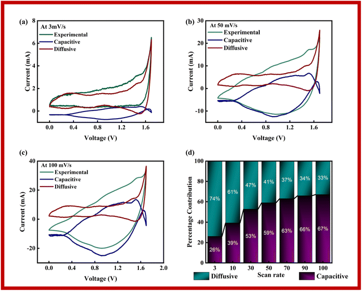
The capacitive, diffusive contributions were also computed at various scan rates using Dunn's model, as stated in eqn (6):
| i(V, ν) = k1(V)ν + k2(V)ν1/2 | (6) |
In Dunn's model, the capacitive current is represented by ‘k1ν’, while ‘k2ν1/2’ denotes the diffusive currents. Plots of the experimental data, that was fitted to it, and the diffusive and capacitive contributions for 3 mV s−1, 50 mV s−1, and 100 mV s−1 are shown in Fig. 9a–c. Due to improper redox reactions at increasing scan rates, it is seen that the capacitive area grows as the scan rate increases. According to the figures, the diffusive component in the scan rate sequence of 3, 50 and 100 mV s−1 diminishes as scan rate increases. The capacitive and diffusive parts, which span both positive and negative zones, effectively encompass the whole scope of the research. Together these components influence the overall findings of the study. The information shown in Fig. 9d demonstrates the percentage of contributions coming from diffusive and capacitive sources at various scan speeds. The underlying reaction mechanisms at each scan rate are better understood thanks to their contributions. The capacitance area increases noticeably as the scan rates rise, suggesting a stronger preference for surface adsorption over redox processes. As a result of having greater time to react, charged species can execute oxidation–reduction processes at lower scan speeds.
4. Conclusion
In this study, we successfully synthesized two MOFs with different linkers, namely 1,2,3,4-cyclopentane-tetracarboxylic acid and Co-BTCA(MOF), both with the same metal center (Co). XRD and SEM are used for initial characterization, followed by half-cell electrochemical characterization. Notably, the hybrid supercapacitor based on Co-CPTC(MOF)//AC demonstrated exceptional performance, with energy density of 23 W h kg−1, and power density of 3400 W kg−1. The supercapacitor also demonstrated exceptional cyclic stability, retaining 95.4% of its initial capacity even after numerous charge–discharge cycles. These findings highlight the intriguing potential of Co-CPTC(MOF)//AC for advanced applications. Furthermore, this research investigates the charge storage behavior of a hybrid supercapacitor device at various scan rates and voltages, which have a substantial impact on capacitive and diffusive contributions. Dunn's model was used to gain insight into the charge storage process. This research also sheds light on the effect of different linkers on the electrochemical activity of potential energy storage systems.Conflicts of interest
There are no conflicts to declare.Acknowledgements
This work was funded by the Researchers Supporting Project Number (RSP2023R429) King Saud University, Riyadh, Saudi Arabia. We gratefully acknowledge financial assistance from the Higher Education Commission of Pakistan, HEC-NRPU project no. 20-17612/NRPU/R&D/HEC/2021.References
- E. Karden, S. Ploumen, B. Fricke, T. Miller and K. Snyder, J. Power Sources, 2007, 168, 2–11 CrossRef.
- Y. Ma, X. Xie, W. Yang, Z. Yu, X. Sun, Y. Zhang, X. Yang, H. Kimura, C. Hou, Z. Guo and W. Du, Adv. Compos. Hybrid Mater., 2021, 4, 906–924 CrossRef CAS.
- S. Pervez and M. Z. Iqbal, Small, 2023, 2305059 CrossRef CAS PubMed.
- W. Xiong, Y. Gao, X. Wu, X. Hu, D. Lan, Y. Chen, X. Pu, Y. Zeng, J. Su and Z. Zhu, ACS Appl. Mater. Interfaces, 2014, 6, 19416–19423 CrossRef CAS PubMed.
- K.-J. Huang, J.-Z. Zhang, G.-W. Shi and Y.-M. Liu, Electrochim. Acta, 2014, 132, 397–403 CrossRef CAS.
- K. Krishnamoorthy, G. K. Veerasubramani, P. Pazhamalai and S. J. Kim, Electrochim. Acta, 2016, 190, 305–312 CrossRef CAS.
- J. Yan, S. Li, B. Lan, Y. Wu and P. S. Lee, Adv. Funct. Mater., 2020, 30, 1902564 CrossRef CAS.
- A. Burke, J. Power Sources, 2000, 91, 37–50 CrossRef CAS.
- M. Minakshi, D. Meyrick and D. Appadoo, Energy Fuels, 2013, 27, 3516–3522 CrossRef CAS.
- A. M. Abioye and F. N. Ani, Renewable Sustainable Energy Rev., 2015, 52, 1282–1293 CrossRef CAS.
- G. Rajasekhara Reddy, N. Ramesh Reddy, G. R. Dillip and S. W. Joo, Energy Fuels, 2022, 36, 5965–5978 CrossRef CAS.
- M. Z. Iqbal and J. Khan, Electrochim. Acta, 2021, 368, 137529 CrossRef CAS.
- M. Shaheen, M. Z. Iqbal, S. Siddique, S. Aftab and S. M. Wabaidur, Mater. Today Sustain., 2023, 23, 100415 CrossRef.
- Y. Hu, L. Fan, A. M. Rao, W. Yu, C. Zhuoma, Y. Feng, Z. Qin, J. Zhou and B. Lu, Natl. Sci. Rev., 2022, 9, nwac134 CrossRef CAS PubMed.
- W. W. Fan, Y. Cheng, L. Y. Zheng and Q. E. Cao, Chem.–Eur. J., 2020, 26, 2766–2779 CrossRef CAS PubMed.
- C. Janiak and J. K. Vieth, New J. Chem., 2010, 34, 2366–2388 RSC.
- C. Li, J. Wang, Y. Yan, P. Huo and X. Wang, Chem. Eng. J., 2022, 446, 137108 CrossRef CAS.
- L. E. Kreno, K. Leong, O. K. Farha, M. Allendorf, R. P. Van Duyne and J. T. Hupp, Chem. Rev., 2012, 112, 1105–1125 CrossRef CAS PubMed.
- A. M. Rabon, Synthesis of MOFs for Low Valent, Low Coordinate Metal Stabilization and Catalysis, The University of Toledo, 2021 Search PubMed.
- K. O. Kirlikovali, S. L. Hanna, F. A. Son and O. K. Farha, ACS Nanosci. Au, 2023, 3, 37–45 CrossRef CAS PubMed.
- S. Li and F. Huo, Nanoscale, 2015, 7, 7482–7501 RSC.
- O. K. Farha, I. Eryazici, N. C. Jeong, B. G. Hauser, C. E. Wilmer, A. A. Sarjeant, R. Q. Snurr, S. T. Nguyen, A. Ö. Yazaydın and J. T. Hupp, J. Am. Chem. Soc., 2012, 134, 15016–15021 CrossRef CAS PubMed.
- S. L. James, Chem. Soc. Rev., 2003, 32, 276–288 RSC.
- X.-G. Han, P.-F. Wang, Y.-H. Zhang, H.-Y. Liu, J.-J. Tang, G. Yang and F.-N. Shi, Inorg. Chim. Acta, 2022, 536, 120916 CrossRef CAS.
- F. H. Allen, Acta Crystallogr., Sect. B: Struct. Sci., 2002, 58, 380–388 CrossRef PubMed.
- L. Zhang, Q.-P. Lin, Z.-J. Li, J. Zhang, Y.-Y. Qin, J.-K. Cheng and Y.-G. Yao, CrystEngComm, 2009, 11, 1201–1203 RSC.
- R.-X. Yao, Z.-M. Hao, C.-H. Guo and X.-M. Zhang, CrystEngComm, 2010, 12, 4416–4423 RSC.
- L.-F. Huang, C.-C. Ji, Z.-Z. Lu, X.-Q. Yao, J.-S. Hu and H.-G. Zheng, Dalton Trans., 2011, 40, 3183–3190 RSC.
- Y. Zhang, Z. Song, L. Miao, Y. Lv, L. Li, L. Gan and M. Liu, Chem. Eng. J., 2023, 467, 143497 CrossRef CAS.
- Y. Qin, Z. Song, L. Miao, C. Hu, Y. Chen, P. Liu, Y. Lv, L. Gan and M. Liu, Chem. Eng. J., 2023, 470, 144256 CrossRef CAS.
- Y. Zhang, Z. Song, L. Miao, Y. Lv, L. Gan and M. Liu, ACS Appl. Mater. Interfaces, 2023, 15, 35380–35390 CrossRef CAS PubMed.
- K. Wickramaarachchi and M. Minakshi, Ceram. Int., 2022, 48, 19913–19924 CrossRef CAS.
- K. Wickramaarachchi and M. Minakshi, J. Energy Storage, 2022, 56, 106099 CrossRef.
| This journal is © The Royal Society of Chemistry 2024 |

