 Open Access Article
N-doped CNTs wrapped sulfur-loaded hierarchical porous carbon cathode for Li–sulfur battery studies†
Arunakumari Nulu ,
Venugopal Nulu
 and
Keun Yong Sohn
 *
*
Department of Nanoscience and Engineering, Center for Nano Manufacturing, Inje University, 197 Inje-ro, Gimhae, Gyeongnam-do 50834, Republic of Korea. E-mail: ksohn@inje.ac.kr
First published on 15th January 2024
Abstract
Lithium–sulfur (Li–S) batteries are considered promising next-generation energy storage devices due to their low cost and high energy density (2600 W h kg−1). However, the practical applicability of Li–S batteries is hindered by the insulating nature of sulfur cathodes, and the high solubility of polysulfides (Li2Sx, 3 < x ≤ 8) which are formed during the electrochemical process. Integrating sulfur into the carbon host is an effective way to enhance the conductivity of the electrode which hampers the shuttling effect of the polysulfides. Here in this study, hierarchical porous carbon structures (HPC) are prepared from spent coffee waste (SCW) by the KOH activation process and are encapsulated with sulfur (SHPC) which increases the interaction between sulfur and carbon and enhances both the electronic and ionic conductivities. Further wrapping of SHPC with N-doped multi-walled carbon nanotubes (NCNTs) gives a SHPC-NCNT composite, which alleviates the shuttling of polysulfides by trapping them and ensures the required conductivity to the sulfur cathode during the Li+ reactions. When studied as a cathode material for Li–S batteries, the prepared cathode showed 664 and 532 mA h g−1 specific capacities after 150 cycles at 0.2C and 0.5C, respectively. The stable cyclability and rate capability properties of SPHCNCNT suggest that the prepared sulfur composite is suitable as a cathode material for Li+ energy storage applications.
1. Introduction
With the rapid advancement of present-generation electric vehicles, portable electronic devices need high energy/power density storage systems with safe, stable, and long-life features.1,2 The ever-growing requirement for high-energy storage systems drives researchers to investigate the further development of Li-based rechargeable batteries. Li-ion batteries (LIBs) with graphite anode and conventional Li-metal oxide cathodes cannot reach the required high energy/power densities due to the restricted theoretical capacities of graphite anode (∼372 mA h g−1) and Li-metal oxide cathodes (∼270 mA h g−1), which hampers further progression of LIB technology.3,4 In this aspect, Li–S batteries have emerged as one of the most promising alternative rechargeable batteries owing to their low cost, lightweight, and safety characteristics. The arrangement of the Li-metal anode (theoretical capacity of 3860 mA h g−1) with the sulfur cathode (theoretical capacity of 1675 mA h g−1) can achieve significantly higher theoretical energy densities of 2500 W h kg−1 or 2800 W h L−1 with respect to the weight or volume basis, with complete conversion of sulfur into Li2S [S8 + 16Li+ + 16e− → 8Li2S] in the electrochemical process, which is several times higher than that of the conventional Li-ion rechargeable batteries.5–8 During the discharging process, Li+ ions are reacted with sulfur and form long-chained polysulfides, further reduction converted long-chained polysulfides to short-length sulfides, Li2S4, Li2S2, and Li2S as the final product. In the charging process, Li+ ions are moved toward the Li-metal anode, and sulfur is formed at the cathode. High theoretical capacity (1675 mA h g−1), low cost and non-toxic nature, and safer operational voltages (∼2.1 V) of sulfur are advantageous and make it a favorable cathode for Li–S batteries.9–11 Although Li–S batteries have considerable advantages, their development is in slow-pace due to a few tough challenges, such as dendrite formation from Li-anode, insulating nature, large volume expansion (80%) of sulfur, and shuttling effect of lithium polysulfides during the redox process. These factors lead to the loss of active sulfur in the form of polysulfide dissolution (Li2Sx, 4 ≤ x ≤ 8), thus utilization of low active material causes poor cyclability, and rapid capacity decline and obstructs the practical applications of Li–S batteries.12–16 Respective of these challenges, considerable developments in cell components such as protective layers for Li-metal anode.17,18 and alternative anode materials to alleviate the Li-dendrites and control the short circuit problems.19–21 Different types of electrolytes are prepared to hinder the polysulfide dissolution resulting in some promising results.22–24 On the other hand, the researchers are more focused on the development of sulfur cathodes to achieve high energy and power densities. Incorporating sulfur with carbon hosts is a promising approach to alleviate the challenges mentioned above. Different types of carbons/carbonaceous hosts such as mesoporous carbons, microporous carbon, CNTs, graphite, graphene, and carbon fibers have been studied for sulfur cathodes.25–30 Impregnating sulfur into these carbon materials improves the electric and ionic conductivity affords the required buffering volume during redox reactions and mitigates the dissolution of polysulfides by trapping them into the carbon matrix. To improve the confinement ability, highly porous carbon hosts are required, so that they can have high adsorption capacity along with large storage space for sulfur and afford large buffer volume to the sulfur cathode.31–33Having ordered pores with different diameters, hierarchically porous carbon (PC) materials exhibit high performances in various applications such as energy storage, deionization, CO2 capture, catalyst, etc.34–38 The porous architectures of the host can accommodate large buffering volumes to sulfur and trap the polysulfide species during Li+ reactions. The conductive nature of the host is helpful for faster electron and Li+ transportation throughout the active material.39,40
The synthesis procedures of porous carbon need sophisticated equipment, tiresome chemical reactions, and template-removing processes.41–43 J. Pang et al. synthesized nanoporous carbon from TEOS and silica gel, sucrose precursors by the sol–gel process followed by a silica template removal procedure.44 Xiulei et al. synthesized highly ordered nanostructured carbon by using a chemical method using Pluronic P123 (EO20PPO70EO20) and TEOS precursors followed by a hard template removing process.45 Biomass-derived carbon materials with a variety of natural porous structures are largely invested nowadays due to their sustainability, environmental friendliness, and low cost. Therefore, bio-mass materials like wood, sawdust, nut shells, grass, industrial waste, algae, and crop residues are widely used for the preparation of PC materials.46 Pyrolysis of biomass/waste material followed by the KOH activation process is the most convenient and extensively used method to prepare PCs. During the pyrolysis process, the organic components from biomass are transformed into volatile substances and residual biochar. The properties of biochar mainly depend on the nature of the precursor matter, the temperature, and the heat rate of the pyrolysis process. The following activation process makes the biochar partly oxidize promotes the pores/porosity and modifies the surface functional groups.29,47 Xia et al. prepared nitrogen and oxygen dual-doped HPC from rapeseed meal, with high meso/micropores and high surface area. The prepared HPC and sulfur composite delivered 512 mA h g−1 capacity after 200 cycles at 0.1C.48 Ren et al. derived HPC from soybeans and loaded with sulfur to make sulfur/C active composite and studied for Li–S batteries. The prepared S/C composite showed a large capacity of 950 mA h g−1 with high energy efficiencies with a high sulfur loading of 5.5 mg cm−2, which is closer to the practical applications.49
Considering the aforementioned facts, here in this study we chose spent coffee waste (Dunkin Donuts, South Korea) as a biomass carbon source rather than purchased chemicals, which greatly reduces the cost of precursor materials and can yield scalable production output. From the spent coffee waste carbon source material, novel hierarchical porous carbon (HPC) structures are prepared via facile pyrolysis and KOH activation approach. The prepared porous carbons are loaded with sulfur by a typical melt-diffusion technique.28 The prepared composite was further wrapped with N-doped CNTs, to afford ionic and electric conductivity and to mitigate the shuttling effect of polysulfides. The prepared sulfur composite delivered considerable cyclability and rate capability results attributed to a continuous conductive network from HPC and N-doped CNTs to sulfur composite, which improves the utilization of sulfur by hampering the polysulfide dissolution.
2. Results and discussion
The step-by-step preparation process of the materials is shown in Fig. 1. From Fig. 1a, the collected spent coffee waste was dried at 100 °C for 24 h to remove any moisture from the material. Then the coffee waste powder was grounded and sieved with a mesh size aperture of about ∼100 μm to get a fine powder. Then the powder was subjected to annealing at 500 °C for 3 h in an argon atmosphere using a tubular furnace to convert the organic material into a black char. The obtained black char was added with KOH with 1![[thin space (1/6-em)]](https://www.rsc.org/images/entities/char_2009.gif) :
:![[thin space (1/6-em)]](https://www.rsc.org/images/entities/char_2009.gif) 3 ratios and mixed well for 1 h and heat treated at 800 °C for 3 h in the same condition. The obtained material was then washed with 1 M HCl solution to remove any –OH groups in the material and followed by distilled water washing several times to make it neutral. The material was then dried overnight at 80 °C to gain hierarchical porous carbon (HPC) structures. The preparation process of the SHPC-NCNT composite is shown in Fig. 1b, where sulfur powder was added with the prepared HPC structures with 85
3 ratios and mixed well for 1 h and heat treated at 800 °C for 3 h in the same condition. The obtained material was then washed with 1 M HCl solution to remove any –OH groups in the material and followed by distilled water washing several times to make it neutral. The material was then dried overnight at 80 °C to gain hierarchical porous carbon (HPC) structures. The preparation process of the SHPC-NCNT composite is shown in Fig. 1b, where sulfur powder was added with the prepared HPC structures with 85![[thin space (1/6-em)]](https://www.rsc.org/images/entities/char_2009.gif) :
:![[thin space (1/6-em)]](https://www.rsc.org/images/entities/char_2009.gif) 15 ratios and mixed well with mini ball milling for 30 min. to get a uniform mixture. Then the mixture was sealed with argon and heat treated at 155 °C for 12 h to impregnate sulfur into carbon pores by a typical melt diffusion process to get sulfur-loaded hierarchical porous carbon (SHPC). This SHPC composite was further added with N-doped CNTs, and heat treated at 155 °C for 10 h in an argon atmosphere to get N-CNTs wrapped sulfur-loaded hierarchical porous carbon (SPHC-NCNT). During this process, some amounts of sulfur from SPHC were sublimed and penetrated to the N-CNT matrix, which enhanced the integrity of the composite and further afforded the structural stability, required conductivity, and buffer volume to sulfur. The final sulfur composite SHPC-NCNT is used as a cathode material and studied their electrochemical properties for Li–S batteries. To investigate the synergetic effect of the HPC-NCNT host, the SNCNT cathode was prepared without HPC. For comparison study SHPC composite with sulfur to HPC ratio of 65
15 ratios and mixed well with mini ball milling for 30 min. to get a uniform mixture. Then the mixture was sealed with argon and heat treated at 155 °C for 12 h to impregnate sulfur into carbon pores by a typical melt diffusion process to get sulfur-loaded hierarchical porous carbon (SHPC). This SHPC composite was further added with N-doped CNTs, and heat treated at 155 °C for 10 h in an argon atmosphere to get N-CNTs wrapped sulfur-loaded hierarchical porous carbon (SPHC-NCNT). During this process, some amounts of sulfur from SPHC were sublimed and penetrated to the N-CNT matrix, which enhanced the integrity of the composite and further afforded the structural stability, required conductivity, and buffer volume to sulfur. The final sulfur composite SHPC-NCNT is used as a cathode material and studied their electrochemical properties for Li–S batteries. To investigate the synergetic effect of the HPC-NCNT host, the SNCNT cathode was prepared without HPC. For comparison study SHPC composite with sulfur to HPC ratio of 65![[thin space (1/6-em)]](https://www.rsc.org/images/entities/char_2009.gif) :
:![[thin space (1/6-em)]](https://www.rsc.org/images/entities/char_2009.gif) 35 was also prepared.
35 was also prepared.
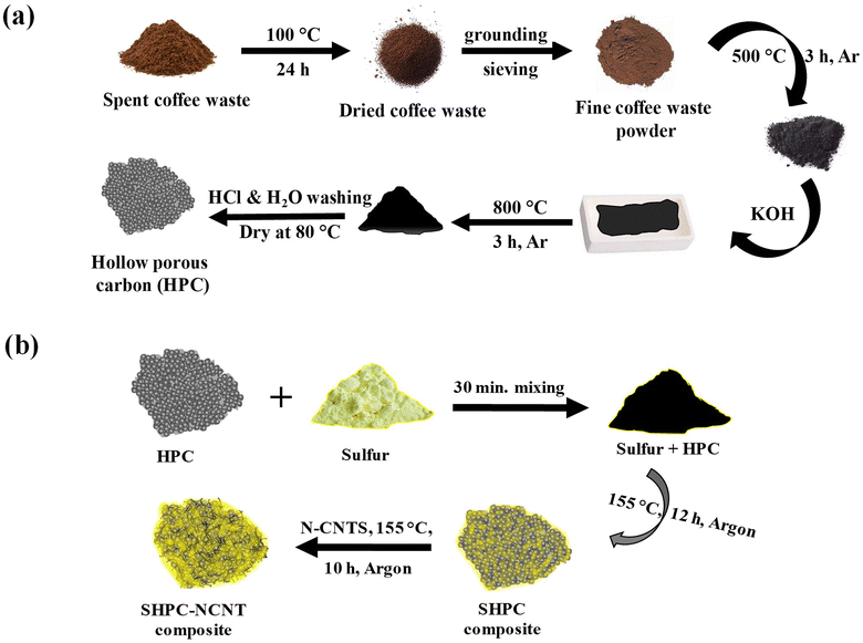 | ||
| Fig. 1 (a) Step-by-step synthesis process of hierarchically porous carbon (HPC) (b) preparation process of N-CNT wrapped sulfur loaded hierarchical porous carbon (SHPC-NCNT) composite. | ||
The XRD patterns of all materials such as pure sulfur, HPC, SHPC, and SHPC-NCNT are shown in Fig. 2a. The prepared HPC shows two broad peaks around 22.3° and 44.3° representing the (002) and (100) diffraction planes of graphitic carbon material, also indicating that the prepared HPC material is in amorphous nature and has low graphitization properties.50 The patterns of sulfur predominantly show sharp crystalline peaks at 2θ = 23.1°, 25.8°, 27.8°, and 31.4° corresponding to the (222), (026), (040), and (044) planes of orthorhombic phases of crystalline sulfur (JCPDS No. 08-0247).21 The composite SHPC showed diffraction peaks similar to that of elemental sulfur with lesser intensities, indicating that the surface of the porous carbons is successfully covered by sulfur. After N-CNTs wrapping, the peak intensities further decreased indicating high dispersion of sulfur into the carbonaceous materials. The broad peak from 2θ = 22° to 28° is attributed to the synergetic of HPC and N-CNTs matrices and the crystalline peaks are related to the sulfur.27–29 indicating uniform dispersion of sulfur into HPC and N-CNTs matrices. The XRD patterns of CNTs and N-doped CNTs are shown in Fig. S1a,† where 25.6° and 42.8° are corresponding to (002) and (100) planes of carbon. After N-doping, the peak intensities are significantly decreased and no impurity peaks and peak shifts are observed indicating no possible reactions occurred during the N-doping process.51 The XRD patterns of other prepared SHPC material with 65![[thin space (1/6-em)]](https://www.rsc.org/images/entities/char_2009.gif) :
:![[thin space (1/6-em)]](https://www.rsc.org/images/entities/char_2009.gif) 35 ratios of sulfur to HPC (SHPC-6535) are depicted in Fig. S1b† along with SHPC (for comparison), where, the broad peak from 22° to 28° reflecting from the (002) plane of porous carbon, where the sharp peaks represent the crystalline sulfur indicating the dispersion sulfur into porous carbon structures.52,53 This broad peak did not appear in the SPHC composite with 85
35 ratios of sulfur to HPC (SHPC-6535) are depicted in Fig. S1b† along with SHPC (for comparison), where, the broad peak from 22° to 28° reflecting from the (002) plane of porous carbon, where the sharp peaks represent the crystalline sulfur indicating the dispersion sulfur into porous carbon structures.52,53 This broad peak did not appear in the SPHC composite with 85![[thin space (1/6-em)]](https://www.rsc.org/images/entities/char_2009.gif) :
:![[thin space (1/6-em)]](https://www.rsc.org/images/entities/char_2009.gif) 15 ratios (SHPC in Fig. 2) due to the presence of high amounts of sulfur content and low amounts of HPC. The accurate amounts of sulfur loading in the prepared materials are determined by the TGA from 30° to 800 °C in the argon atmosphere. The TGA profiles of pure sulfur, SHPC, and SHPC-NCNT are shown in Fig. 2b. The pure elemental sulfur completely evaporated after 300 °C. The sulfur content in SHPC is measured as 82.5%, which is very close to the amount of sulfur added in the material preparation, indicating complete confinement of sulfur within the pores of carbon. The weight loss of SHPC after 350 °C is related to the thermal degradation of HPC, and it is stabilized after 650 °C.54,55 The amount of sulfur loading in SHPC-NCNT is determined as 67.2%, which is a reasonable loading of sulfur to achieve high specific capacities. The higher amounts of sulfur loading in composite materials with good conductive carbons are advantageous to attain high energy densities and are applicable as a potential cathode for future energy storage applications.
15 ratios (SHPC in Fig. 2) due to the presence of high amounts of sulfur content and low amounts of HPC. The accurate amounts of sulfur loading in the prepared materials are determined by the TGA from 30° to 800 °C in the argon atmosphere. The TGA profiles of pure sulfur, SHPC, and SHPC-NCNT are shown in Fig. 2b. The pure elemental sulfur completely evaporated after 300 °C. The sulfur content in SHPC is measured as 82.5%, which is very close to the amount of sulfur added in the material preparation, indicating complete confinement of sulfur within the pores of carbon. The weight loss of SHPC after 350 °C is related to the thermal degradation of HPC, and it is stabilized after 650 °C.54,55 The amount of sulfur loading in SHPC-NCNT is determined as 67.2%, which is a reasonable loading of sulfur to achieve high specific capacities. The higher amounts of sulfur loading in composite materials with good conductive carbons are advantageous to attain high energy densities and are applicable as a potential cathode for future energy storage applications.
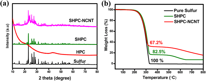 | ||
| Fig. 2 (a) XRD pattern of pure sulfur, HPC, SHPC, and SHPC-NCNT materials (b) TGA results of pure sulfur, HPC, and SHPC-NCNT materials. | ||
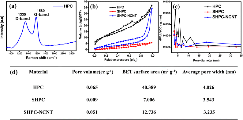
The elemental composition and graphitization property of the prepared HPC is analyzed by Raman spectroscopy and the results are shown in Fig. 3a. The two broad peaks at 1335 cm−1 and 1580 cm−1 are appeared in Raman spectra. It is known that the D band around 1335 cm−1 corresponds to disordered and structurally defective regions containing the sp3 carbons. In contrast, the G band at 1580 cm−1 corresponds to the C![[double bond, length as m-dash]](https://www.rsc.org/images/entities/char_e001.gif) C bonds in graphitic carbons with sp2 hybridized carbon. Hence the ID/IG ratio is indicative of the amorphous degree of the material. The ID/IG of prepared HPC is 0.92 indicating the high surface defects or amorphous degree of the prepared HPC, which is beneficial for providing active sites for Li-ion adsorption, reducing their diffusion paths, and improving the electrochemical capacity of the material.56 The porous nature and the pore-size distribution of the prepared HPC and other prepared materials SHPC and SHPC-NCNT are investigated by the nitrogen adsorption–desorption isotherms at 77 K, are shown in Fig. 3b and c respectively. According to the IUPAC classification, type IV mesoporous isotherms are shown by HPC and SHPC-NCNT materials, and type II nonporous isotherms are shown by SHPC. This could be due to that the HPC has more pores mostly in the range of 2 to 5 nm, which shows a surface area of 40.3 m2 g−1, whereas SHPC shows a lower surface area of 7 m2 g−1 could be due to the diffusion of sulfur into the pores of HPC and covers its pores and surface. However, the surface area of SHPC-NCNT (12 m2 g−1) is increased and could be respective to the presence of N-CNTs in the composite. The BJH pore size distribution curves are depicted in Fig. 3c, where HPC has dense pores in the mesoporous region, whereas the other two materials SHPC and SHPC-NCNTs have less pore density in that region due to the blocking of pores by elemental sulfur. The increased surface area enhanced the faster Li+ transportations, and mesopores from SHPC-NCNT allow fast wettability of active material and afford the buffering volume to elemental sulfur.41,45 The average pore volume, surface area, and pore widths of all three samples are summarized in Fig. 3d.
C bonds in graphitic carbons with sp2 hybridized carbon. Hence the ID/IG ratio is indicative of the amorphous degree of the material. The ID/IG of prepared HPC is 0.92 indicating the high surface defects or amorphous degree of the prepared HPC, which is beneficial for providing active sites for Li-ion adsorption, reducing their diffusion paths, and improving the electrochemical capacity of the material.56 The porous nature and the pore-size distribution of the prepared HPC and other prepared materials SHPC and SHPC-NCNT are investigated by the nitrogen adsorption–desorption isotherms at 77 K, are shown in Fig. 3b and c respectively. According to the IUPAC classification, type IV mesoporous isotherms are shown by HPC and SHPC-NCNT materials, and type II nonporous isotherms are shown by SHPC. This could be due to that the HPC has more pores mostly in the range of 2 to 5 nm, which shows a surface area of 40.3 m2 g−1, whereas SHPC shows a lower surface area of 7 m2 g−1 could be due to the diffusion of sulfur into the pores of HPC and covers its pores and surface. However, the surface area of SHPC-NCNT (12 m2 g−1) is increased and could be respective to the presence of N-CNTs in the composite. The BJH pore size distribution curves are depicted in Fig. 3c, where HPC has dense pores in the mesoporous region, whereas the other two materials SHPC and SHPC-NCNTs have less pore density in that region due to the blocking of pores by elemental sulfur. The increased surface area enhanced the faster Li+ transportations, and mesopores from SHPC-NCNT allow fast wettability of active material and afford the buffering volume to elemental sulfur.41,45 The average pore volume, surface area, and pore widths of all three samples are summarized in Fig. 3d.
The surface morphology and structures of HPC, N-CNT, investigated by SEM, and TEM, and the images are portrayed in Fig. 4. The highly porous morphology with abundant pores with 2–5 μm voids, interconnected with thin walls are observed for HPC material and the respective SEM are depicted in Fig. 4a. The high magnification SEM image from Fig. 4b shows that the average void size in HPC is about 2.5 μm. The TEM image of HPC is depicted in Fig. 4c, shows pores of HPC (highlighted with yellow), and the high-resolution TEM (HR-TEM) image is shown in the inset of Fig. 4c, shows the average wall thickness about 80–120 nm, which is highly favorable for high sulfur loading and beneficial for faster electronic and ionic transportation during electrochemical reactions. Moreover, the abundant pores of HPC can provide ample buffer spaces and accommodate large volume changes of sulfur upon reversible Li+ reactions. The TEM images of N-CNTs are shown in Fig. 4d and the corresponding TEM-EDX elemental mapping and respective spectra are displayed in Fig. 4e–g. From the mapping, the N signal overlaps with the C signal indicating the successful N-doping in CNTs and confirmed by the spectrum shown in Fig. 4g.
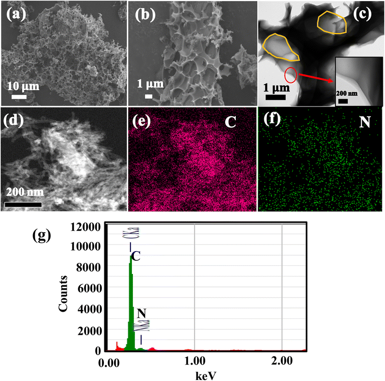 | ||
| Fig. 4 (a and b) SEM images of HPC, (c) HR-TEM image of HPC (d) TEM image of N-CNTs (e) C signal mapping (f) N signal mapping of image (d), (g) TEM-EDX spectra of N-CNTs. | ||
From Fig. 5a and b, the SEM images of SHPC structures show no pores due to the occupation of sulfur into the voids of HPC, indicating the complete and even dispersion of sulfur into HPC. The integrated structures of SHPC-NCNTs are shown in Fig. 5c and d. The images also indicate that the SHPC composite is successfully wrapped by N-CNTs and interconnected with the structures, giving extra structural stability to the sulfur cathode. A closer view of SHPC-NCNT is shown in the inset of Fig. 5d. The TEM images of SHPC-NCNT are depicted in Fig. 5e and f, confirming the successful wrapping of SHPC structures with N-CNTs. The synergetic of HPC and N-CNT structures provide sufficient space along with rapid transport channels for Li+ reactions which eventually lead to achieving high and stable specific capacities.
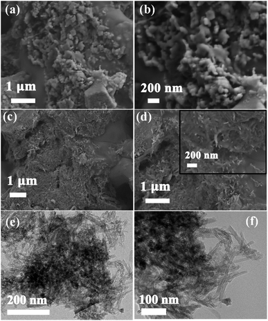 | ||
| Fig. 5 SEM images of (a and b) SDC8515 (c and d) SCDCNCNT8515, TEM images of (e and f) SHPC-NCNT composites. | ||
The SEM-EDX elemental mapping of SHPC-NCNT is shown in Fig. S2.† The SEM image and corresponding EDX element layered images are shown in Fig. S2a and b† respectively. The S mapping in Fig. S2c† indicates its uniform distribution in SHPC-NCNT. The mapping of C from Fig. S2d† resulting from the synergetic of HPC and N-CNTs, where the N-mapping from Fig. S2e† signal overlaps with the C mapping signal, confirms the N-doping in the carbon matrix. The doped N greatly improves the conductivity of CNTs and encourages faster kinetics in the composite. The wrapped N-CNTs eventually protect the overall structures of the composite confine the polysulfides during redox reactions and alleviate the shuttle effect. Fig. S2f† is the SEM-EDX spectrum of SHPC-NCNT, where S, C, and N signals are depicted and the inset in Fig. S2f† shows the elemental composition of respective elements.
The SHPC-NCNT composite was analyzed by XPS, to determine surface chemical composition, and the resultant plots are depicted in Fig. 6a–d. The wide survey scan spectrum from Fig. 5a represents the presence of S, C, and N in the prepared SHPC-NCNT composite, respectively. The curve–fitting method was employed to distinguish the chemical states of the S, C, and N. The high-resolution XPS for S 2p is shown in Fig. 6b, where the binding energies 163.6 eV and 164.8 eV with a separation of 1.2 eV are typical characteristics of elemental sulfur from 2p1/2 and 2p3/2 in SHPC-NCNT composite. The other broad peaks at the binding energy of 164.0 eV and 165.4 eV result from the C–S bonds representing the bonds of sulfur with HPC and N-CNTs. The weak peak at 168.0 eV is due to sulfate species formed by the oxidation of sulfur.28 The high-resolution spectrum of C 1s is depicted in Fig. 6c, in which the peaks at binding energies 284.2 eV assigned to the C![[double bond, length as m-dash]](https://www.rsc.org/images/entities/char_e001.gif) C/C–C bonds, and the peak at 284.9 eV and 285.8 eV are responsible for C–S bonds and C–N bonds, respectively.46 The N 1s high-resolution spectrum is depicted in Fig. 6d, fitted into three peaks at the binding energies of 397.7, 399.9, and 402.1 eV are related to the related to pyridinic, pyrrolic, and graphitic N respectively. The N 1s spectrum further confirms the successful N-doping in CNTs which encourages the conductivity and Li+ diffusion properties in the sulfur composite.51 The XPS results are well consistent with the SEM-elemental mapping results.
C/C–C bonds, and the peak at 284.9 eV and 285.8 eV are responsible for C–S bonds and C–N bonds, respectively.46 The N 1s high-resolution spectrum is depicted in Fig. 6d, fitted into three peaks at the binding energies of 397.7, 399.9, and 402.1 eV are related to the related to pyridinic, pyrrolic, and graphitic N respectively. The N 1s spectrum further confirms the successful N-doping in CNTs which encourages the conductivity and Li+ diffusion properties in the sulfur composite.51 The XPS results are well consistent with the SEM-elemental mapping results.
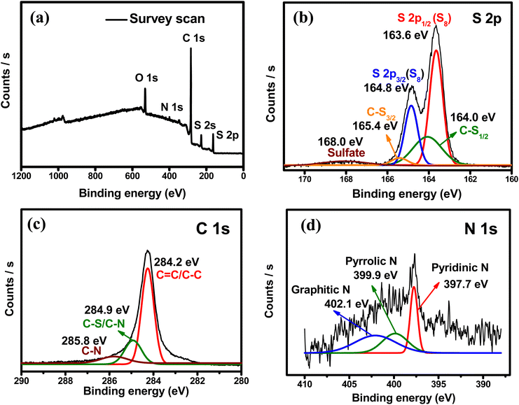 | ||
| Fig. 6 XPS spectra (a) survey scan (b) high-resolution S 2p (c) high-resolution C 1s (d) high-resolution N 1s of SHPC-NCNT composite. | ||
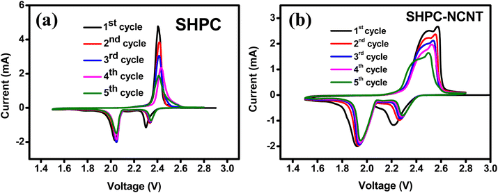
Different types of electrochemical tests, such as cyclic voltammetry (CV), cyclability, rate capability, and impedance are investigated to evaluate the performance of the prepared SHPC-NCNT composite as a cathode material for Li–S batteries. The CV tests are conducted to evaluate the redox behavior and electrochemical mechanism within the voltage window of 1.5 to 2.8 V at 0.1 mV s−1 scan rate. The CV profiles for the first five cycles of SHPC and SHPC-NCNT are depicted in Fig. 7a and b and the CV plots for SHPC-6535 are shown in Fig. S3a† for comparison. For SHPC, two reduction peaks are observed in the cathodic scan at 2.05 V and 2.3 V representing the conversion of pure sulfur into long-chain poly sulfides (Li2Sn, 4 ≤ n ≤ 8) and the decomposition of long-chain poly sulfides to a sort chain polysulfides (Li2Sn, 1 ≤ n ≤ 4). In the anodic scan, the prominent peak at 2.4 V, resulted from the reverse reaction of Li2S into Li-polysulfide and sulfur. The CV profile of SHPC-NCNT in Fig. 6b shows two reduction peaks at 1.9 V and 2.2 V resulting from the two-step conversion reaction of sulfur into Li2S. But for the anodic scan of the SHPC-NCNT electrode has two oxidation peaks at 2.48 V and 2.57 V related to faster reaction kinetics due to the wrapped N-CNTs which provide high electronic conductivity and improved interfacial stability between the sulfur and electrolyte and ensure faster kinetics by minimizing the polysulfide dissolution. The missing oxidation peak in SHPC is related to the slow and sluggish reaction kinetics in the material.57 The 1st cycles for CV measurements for SHPC and SHPC-NCNTs are compared and shown in Fig. S3a,† in which the overpotential observed in both cathodic and anodic sweeps in SHPC-NCNT electrode and the attributed polarization caused by the phase transition from the reaction processes of sulfur and polysulfides. Further, the slow wettability of the wrapped N-CNTs by the electrolyte in the early stages could also be a cause for the overpotential of electrodes with NCNTs. The large integrated CV area of SHPC-NCNT suggests higher electrochemical storage capacity and could be attributed to the good electrical conductivity afforded by N-CNTs, which also offers a worthy connection between sulfur, HPC, and CNTs leading to excellent structural stability of SHPC-NCNT cathode.58 The overlapping of CV profiles from SHPC and SHPC-NCNT after the first cycle results from the high reversibility and electrochemical stability of the prepared electrodes. Moreover, in the following cycles, the reduction peak slightly shifts towards higher voltage, and the oxidation peaks shift towards lower voltage due to the activation process of sulfur cathodes, respective to the formation of ionic and electronic channels in the electrode material leading to lower polarization and stable capacities.12,13,29 The CV profile for the first five cycles of SHPC-6535 shown in Fig. S3b† also showed a similar CV profile as SHPC and SHPC-NCNT. All these CV results are in good agreement with the typical characteristic behavior of sulfur cathode.
The galvanostatic charge/discharge profiles for the first three cycles for SHPC and SHPC-NCNT at applied currents of 0.2C in the voltage window of 1.5–2.8 V are shown in Fig. S4a and b† respectively. As observed, the SHPC electrode showed initial higher specific capacities compared to SHPC-NCNT electrodes could be due to the higher amounts of sulfur loading in the SHPC electrode (see Fig. 2b). In the first cycle, the SHPC electrode delivered 1121/1075 mA h g−1 specific capacity with 95.8% of initial coulombic efficiency (ICE). In the second and third cycles, the SHPC electrode showed 1054/1035 mA h g−1 and 1019/995 mA h g−1 specific capacities with 98% and 97% of coulombic efficiencies (CE), respectively. On the other hand, the SHPC-NCNT electrode delivered initial capacities of 954/889 mA h g−1 with 93% of ICE which is low compared to the ICE of the SHPC electrode and it could be due to the accumulation of more Li+ in the N-CNT matrix present in the composite during initial cycles. The higher carbon content will increase the specific surface area of the active material/composite material and result in excessive formation of SEI films, resulting in the degradation of the initial coulombic efficiency (ICE). In the later cycles, the SHPC-NCNT electrode showed 887/848 mA h g−1, and 853/830 mA h g−1 specific capacities with 95% and 97% of CEs which is a good sign of high reversible performance. The CE is gradually increased with cycling and stabilizes above 98% for the SHPC-NCNT electrode. The reaction path of the charge/discharge profiles is in good agreement with the typical characteristics of sulfur cathodes in Li–S batteries.16,21 To investigate the optimal amounts of carbon hosts in sulfur cathodes and to investigate the synergetic effect of HPC-NCNT host, the prepared cathodes SHPC-6535, SNCNT and SHPC are studied for long-term cyclability at 0.2C rate and the results are depicted in Fig. S5.† As seen in Fig. S5,† SHPC-6535 showed poor cyclability results compared to the SHPC, and SNCNT electrodes, and it could be due to the higher amounts of carbon in the SHPC composite, which decreases the overall theoretical capacity of the composite, indicating the requirement of optimal amounts of carbon host for sulfur loading which plays a crucial role in sulfur composites. When comparing the performances of SHPC and SNCNT, after 100 cycles SHPC delivered 555/551 mA h g−1 specific capacity, whereas SNCNT electrode delivered 454/451 mA h g−1 specific capacity suggesting the key role played by HPC structures in attaining stable capacities than N-CNTs. Though SHPC showed better results than SNCNT, the individual electrochemical performances of both electrodes are not enough to reach higher energy densities of Li+ energy storage applications.
The long-term cyclability tests were carried out for the prepared SHPC and SHPC-NCNT composites at low currents of 0.2C for 150 cycles and respective specific capacity vs. cycle number plots along with corresponding CEs are depicted in Fig. 8a. The calculated volumetric energy densities for HPC and SHPC-NCNTs at 0.2C are 648 and 593 W h L−1. From the plots, it is observed that the SHPC electrode initially showed higher specific capacities but eventually dropped and reached 522/520 mA h g−1 after a long 150 charge/discharge cycles with 50% capacity retention compared to 2nd cycle's charge capacity. The gradual decrease in the specific capacities could be due to a lack of conductivity in the composite along with the loss of active material in the form of a shuttling effect. The SHPC electrode has a higher sulfur loading of 82.5 wt%; however, substantial amounts of sulfur could be lost in the form of dissolution in the electrolyte due to the lack of outer confinement protection. Moreover, the insoluble short-chained polysulfides (Li2S/Li2S2) could deposit on the surface of the carbon matrix, which further hampers the effective electrical contact and ionic transportation into the sulfur cathode. These results suggested that the SHPC composite needs further improvement in terms of physical and chemical properties. However, the performance of the SHPC electrode is considerably higher than the other porous carbon/carbon hosts.9,10,29,39 The prepared SHPC cathode also showed higher coulombic efficiencies more than 95% indicating that the prepared HPC could be a promising host for sulfur cathodes. On the other hand, the SHPC-NCNT electrode prepared by wrapping SHPC with N-CNTs showed excellent cycle stability could be owing to the hindering of polysulfide dissolution along with providing excellent conductivity during the electrochemical reaction of sulfur with Li+ ions. The trapping ability of N-CNTs could obstruct the loss of active sulfur leading to stable cycle performance. After 150 cycles, the SHPC-NCNT cathode delivered the capacities of 664/662 mA h g−1 with 99% CE with 75% of capacity retention (compared to 2nd cycle's charge capacity). The overall cyclability results showed higher coulombic efficiencies of more than 99% representing the effective surpass of sulfur dissolution during charge/discharging reactions. Though SHPC-NCNT composite has a lower sulfur content than SHPC, still it showed better cycle stability, signifying the critical role of N-CNTs wrapping in the composite material.
 | ||
| Fig. 8 Cyclability with coulombic efficiency results of SHPC and SHPC-NCNTs composite at (a) 0.2C rate (b) 0.5 rate. | ||
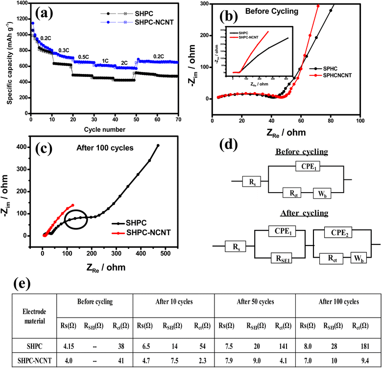
The practical applicability of prepared composites is investigated by applying higher currents of 0.5C for 150 cycles and the specific capacity vs. cycle number plots are depicted in Fig. 8b. The volumetric energy densities for SHPC and SHPC-NCNT at 0.5C are 593 and 438 W h L−1. As seen in Fig. 8b, SHPC showed gradual declined capacities, which could be low utilization of sulfur cathode as a result of the shuttle effect. Though the SHPC electrode delivered an initial capacity of 814/784 mA h g−1, after 150 cycles the capacities reached 357/355 mA h g−1 with 46% of capacity retention. By contrast, SHPC-NCNT composite exhibits an initial specific capacity of 729/692 mA h g−1 and shows stable capacities. After 150 cycles, SHPC-NCNT delivered 532/529 mA h g−1 with 74% capacity retention indicating excellent structural stability of SHPC-NCNT and suppression of the shuttling effect of sulfur by N-CNT wrapping, indicating the crucial role played by the synergetic effect of HPC-NCNT. The specific capacity vs. voltage profiles for the first three cycles of SHPC and SHPC-NCNT electrodes at 0.5C are depicted in Fig. S6.† The charge/discharge profiles showed a similar path as typical sulfur cathode reactions.11,29 The rate capability tests were carried out from 0.1C to 2.0C for both SHPC and SHPC-NCNT electrodes and the results are shown in Fig. 9a. SHPC-NCNT electrode delivered 1146, 763, 653, 606, and 579 mA h g−1 charge capacities at applied C-rates of 0.2C, 0.3C, 0.5, 1C, and 2C respectively. Furthermore, after applying high currents of 2C, the electrode regained a charge capacity of 689 mA h g−1 capacity at 0.2C indicating the stability of the SHPC-NCNT electrode. On the other hand, SHPC electrode delivered 1054, 635, 487, 453, and 423 mA h g−1 capacities at 0.2C, 0.3C, 0.5, 1C, and 2C, respectively, and attained 512 mA h g−1 charge capacity at 0.2C. From C-rate capability results, both prepared electrodes performed well, but the SHPC-NCNT electrode showed better results compared to SHPC owing to its extra conductivity, structural support, and polysulfide trapping ability of N-CNTs in the composite. The electrochemical performance and capacity retentions of HPC-NCNT host material for sulfur cathode are compared to previously reported biomass-derived carbon host materials and other porous carbon hosts and are summarized in Table S1.†
To investigate the electrochemical processes and kinetics of Li–S batteries, electrochemical impedance spectroscopy (EIS) was done in the frequency range of 10 mHz to 10 kHz. EIS was recorded on a Li–S battery with an electrode system with metallic Li anode and prepared sulfur cathodes (SHPC and SHPC-NCNT) at 0.5C, in the potential window of 1.5–2.8 V. The EIS spectra were recorded at different cycle numbers such as 0th cycle (before cycling), 10th cycle, 50th cycle and 100th cycle. The EIS spectra of SHPC and SHPC-CNT electrodes at the 0th cycle and after 100 cycles are depicted in Fig. 9b and c, after the 10th cycle and 50th cycle EIS spectrum is shown in Fig. S7a and b† respectively. The Nyquist plots are composed of a semicircle at a high-frequency region representing the electrode and electrolyte interface charge transfer resistance, and the inclined line at the low-frequency region refers to Warburg impedance (Wb) indicating Li+ diffusion into the active material. The intercept of high frequency on the real axis represents the solution/electrolyte resistance (Rs). RSEI is mainly attributed to the Li/electrolyte interface, due to the formation of the solid electrolyte interface (SEI) layer. Rct corresponds to the charge transfer resistance of poly sulfides on the positive electrode. The lowest Rct values indicate the improved ionic channels and fast transportation of Li+ into the active material. The equivalent circuit models containing Rs, RSEI, Rct, constant phase elements (CPE1 and CPE2), and Warburg impedance (Wb) and summarized impedance values are shown in Fig. 9d and e respectively. As shown in the SHPC and SPHC-NCNT electrodes similar resistance before cycling. But after the 10th, 50th, and 100th cycles, SHPC showed more Rct values compared to SHPC-NCNT, indicating loss of active material in the form of polysulfides in SHPC composite, whereas SHPC-NCNT composite showed lesser Rct values in respective to the captivity of N-CNTs which successfully surpass the polysulfides dissolution and obstruct the loss of active material.27,59
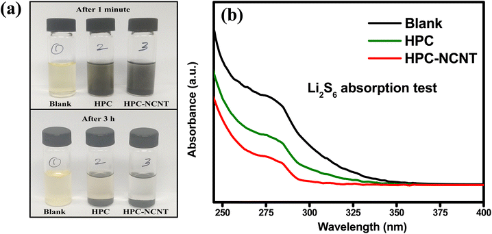
The prepared 5 mM Li2S6 solution (5 ml) was taken in 3 glass containers and 4 mg of HPC and HPC-NCNT were added to the two of the Li2S6 solutions and rested for 3 h. After resting for 3 h, the supernatant liquids were collected and diluted for UV-vis spectra analysis. From Fig. 10a, blank solution, and blank solutions with HPC and HPC-NCNT materials are shown in the time intervals of 1 min. and after 3 h. After resting for 3 h, the bottle with HPC material faded the yellow color a little, but the HPC-NCNT material showed a clear solution indicating the strong ability towards polysulfide trapping. UV-vis spectroscopy was carried out for the diluted supernatant liquids to investigate the polysulfide absorbance ability. The resultant UV-vis spectrum is depicted in Fig. 10b, and the solution with HPC-NCNT showed a lower intensity peak compared to HPC and blank solutions indicating the strong absorption ability of HPC-NCNT host material towards lithium polysulfides.
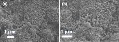
The SEM images of the SHPC-NCNT composite after 150 cycles at 0.2C are depicted in Fig. 11a and b, in which the structures of the composite agglomerated to some extent and there are no cracks are observed. However, there are some pores are observed, in the range of 0.1–0.2 μm, which could be due to the process of lithiation/de-lithiation can cause a large and uneven expansion of the electrode making it porous or the gases formed during electrolyte decomposition could also be the reason. However, further studies are needed for a better understanding of pore formation during the redox reactions of sulfur cathodes. A similar observation was recorded by Li et al. for sodium ion battery studies.60 Though SHPC showed considerable stability in cyclability, and rate capability results with the effect of a hierarchical porous carbon host, which provides sufficient conductivity and buffer volume to sulfur, couldn't control the polysulfide dissolution effectively. The significant improvement of electrochemical properties of SHPC-NCNT results from the wrapping of the N-CNTs framework, which significantly improves the overall conductivity of the composite. The doped N in CNTs also plays a key role in improving the overall conductivity of the composite and resulting in fast kinetics reactions. The synergistic effect of hierarchical porous carbon and N-CNTs matrices effectively traps the dissolved lithium polysulfide shuttling effect by providing chemical barrier interfaces and stimulating the reaction kinetics during redox reactions. Furthermore, the N-CNTs matrix affords substantial buffer volume to the sulfur cathode mitigates the mechanical stress, and improves the structural stability of the composite.
3. Conclusion
In the study, hierarchical porous carbons are prepared via facile pyrolysis followed by a KOH activation approach by using spent coffee waste as a cheap biomass carbon source. These hierarchical porous carbons are used as a carbon substrate host for sulfur cathodes by a typical sulfur impregnation approach. Further wrapping of sulfur and porous carbon composite with N-doped CNTs to make the composite more stable with highly conductive which greatly enhances the electrochemical properties such as cyclability and rate capability. The prepared N-CNTs wrapped sulfur-loaded hierarchical porous carbon composite delivered 664 mA h g−1 and 532 mA h g−1 specific capacities at 0.2C and 0.5C, after 150 cycles with more than 99% of coulombic efficiencies. The impedance results also confirm the better performance of the prepared composite by showing low charge transfer resistances. The enhanced electrochemical properties are attributed to the buffer volume afforded by porous carbon which can hold active sulfur in their pores. The wrapped N-CNTs increase overall conductivity and structural stability. Furthermore, it protected the active material by successfully confining the dissolved polysulfides efficiently and surpassed the shuttling effect. The synergetic effect of HPC and N-CNTs makes the sulfur cathode stable after long-term cyclability and rate capability results. This work not only presents the preparation of host materials for sulfur cathode simply and cost-effectively but also suggests a new strategy for preparing advanced porous carbon structures for a wide range of applications.4. Experimental
4.1 Materials preparation processes
![[thin space (1/6-em)]](https://www.rsc.org/images/entities/char_2009.gif) :
:![[thin space (1/6-em)]](https://www.rsc.org/images/entities/char_2009.gif) 3 ratios and well mixed for 1 h. Then the mixture was placed in a tubular furnace and heat treated for 3 h at 800 °C under the argon atmosphere. The obtained carbon powder was washed with 1 M HCl followed by distilled water several times and overnight dried at 80 °C to achieve hierarchical porous carbon (HPC).
3 ratios and well mixed for 1 h. Then the mixture was placed in a tubular furnace and heat treated for 3 h at 800 °C under the argon atmosphere. The obtained carbon powder was washed with 1 M HCl followed by distilled water several times and overnight dried at 80 °C to achieve hierarchical porous carbon (HPC).![[thin space (1/6-em)]](https://www.rsc.org/images/entities/char_2009.gif) :
:![[thin space (1/6-em)]](https://www.rsc.org/images/entities/char_2009.gif) 35 (SHPC-6536) was also prepared. To investigate the synergetic effect of the HPC-NCNT host, the SNCNT cathode was prepared as SHPC with a sulfur to N-CNTs ratio of 85
35 (SHPC-6536) was also prepared. To investigate the synergetic effect of the HPC-NCNT host, the SNCNT cathode was prepared as SHPC with a sulfur to N-CNTs ratio of 85![[thin space (1/6-em)]](https://www.rsc.org/images/entities/char_2009.gif) :
:![[thin space (1/6-em)]](https://www.rsc.org/images/entities/char_2009.gif) 15.
15.![[thin space (1/6-em)]](https://www.rsc.org/images/entities/char_2009.gif) :
:![[thin space (1/6-em)]](https://www.rsc.org/images/entities/char_2009.gif) 1) dissolved in 1,3-dioxalane and 1,2-dimethoxy ethane (DOL
1) dissolved in 1,3-dioxalane and 1,2-dimethoxy ethane (DOL![[thin space (1/6-em)]](https://www.rsc.org/images/entities/char_2009.gif) :
:![[thin space (1/6-em)]](https://www.rsc.org/images/entities/char_2009.gif) DME in 1
DME in 1![[thin space (1/6-em)]](https://www.rsc.org/images/entities/char_2009.gif) :
:![[thin space (1/6-em)]](https://www.rsc.org/images/entities/char_2009.gif) 1, v/v) and stirred vigorously for 24 h in argon-filled glovebox at 60 °C to produce brownish red Li2S6 solution. Then the Li2S6 solution was diluted to 5 mM for polysulfide adsorption test.
1, v/v) and stirred vigorously for 24 h in argon-filled glovebox at 60 °C to produce brownish red Li2S6 solution. Then the Li2S6 solution was diluted to 5 mM for polysulfide adsorption test.4.2 Materials characterization
The crystallinity of the prepared materials was analyzed by X-ray diffraction technique (Cu Kα radiation, λ = 1.5406 Å). The amounts of carbon present in the prepared materials were determined by thermogravimetric analysis (TGA) in the argon atmosphere from 30 °C to 800 °C. Scanning electron microscopy (SEM) was used for morphology and structural analysis. Brunauer–Emmett–Teller (BET), Barrett, Joyner, and Halenda (BJH) methods were employed to analyze the specific surface area and pore size distribution of prepared samples. X-ray photoelectron spectroscopy was used to determine the elemental composition of the materials. UV-vis spectroscopy was employed to analyze the polysulfide absorption ability of the materials.4.3 Electrochemical measurement
All electrochemical tests for the prepared electrode materials were analyzed by using 2032R button-type coin cells. All working electrodes were prepared by using 80% active material mixed with 10% super P carbon conductive agent and 10% polyvinylidene difluoride (PVDF) binder in N-methyl-2-pyrrolidone (NMP) solvent. All the components are well mixed by a mini ball mill for 30 min. to make a uniform slurry. Then the slurry was coated on a carbon-coated alumina foil substrate by using a typical doctor blade technique with 20 μm thickness. The electrode was dried in a vacuum oven at 60 °C for 10 h to remove excess NMP solvent. Then the electrode was punched into 14 mm disks and used as a cathode. The active material loading was ∼2.1 mg cm−2. Metallic Li was used as a counter electrode without any pre-surface cleaning and polypropylene (PP Wellcos Corporation, Separator 2400) with a 19 mm diameter was used as a separator. The electrolyte consisted of 1 M lithium bis-(trifluoromethyl sulfonyl-imide) (LiTFSI, Aldrich, 99.95%), and 0.25 M lithium nitrate (LiNO3, Alfa Aesar, 99.98%, anhydrous) in a solvents 1,2-dimethoxy ethane (DME, Sigma Aldrich, 99.5%, anhydrous) and 1,3-dioxolane (DOL, Sigma Aldrich, 99.8%, anhydrous), with 1![[thin space (1/6-em)]](https://www.rsc.org/images/entities/char_2009.gif) :
:![[thin space (1/6-em)]](https://www.rsc.org/images/entities/char_2009.gif) 1 (v/v) ratio. All button-type coin cells are fabricated in an argon argon-filled glove box (H2O < 0.1 ppm and O2 < 1 ppm) and all electrochemical tests are carried out at room temperature with a BioLogic cell testing system. The cutoff voltage applied is 1.5–2.8 V. The specific capacities of the cells were calculated based on the weight of the active materials.
1 (v/v) ratio. All button-type coin cells are fabricated in an argon argon-filled glove box (H2O < 0.1 ppm and O2 < 1 ppm) and all electrochemical tests are carried out at room temperature with a BioLogic cell testing system. The cutoff voltage applied is 1.5–2.8 V. The specific capacities of the cells were calculated based on the weight of the active materials.
Author contributions
Conceptualization, A. N.; methodology, A. N. and V. N.; measurement and analysis, A. N.; measurement supervision, K. Y. S., and V. N.; writing – original draft preparation, A. N.; writing – review and editing, K. Y. S., A. N., and V. N.; project administration, A. N.; funding acquisition, K. Y. S. and A. N. All authors have read and agree to the published version of the manuscript.Conflicts of interest
The authors declare that they have no known competing financial interests or personal relationships that could have appeared to influence the work reported in this paper.Acknowledgements
This work was supported by the National Research Foundation of Korea (NRF) (grants 2021R1I1A1A01061270 and 2021R1I1A3059637), funded by the Ministry of Education.References
- M. Winter and R. J. Brodd, Batteries, Chem. Rev., 2004, 104, 4245–4269 CrossRef CAS PubMed
.
- Y. Yang, G. Zheng and Y. Cui, Chem. Soc. Rev., 2013, 42, 3018–3032 RSC
.
- B. Dunn, H. Kamath and J. M. Tarascon, Science, 2011, 334, 928–935 CrossRef CAS PubMed
.
- C. Liu, F. Li, L. P. Ma and H. M. Cheng, Adv. Mater., 2010, 22, E28–E62 CAS
.
- D. W. Wang, Q. Zeng, G. Zhou, L. Yin, F. Li, H. M. Cheng, I. R. Gentle and G. Q. M. Lu, J. Mater. Chem. A, 2013, 1, 9382–9394 RSC
.
- J. Q. Huang, Q. Zhang and F. Wei, Energy Storage Mater., 2015, 1, 127–145 CrossRef
.
- H. Yamin, A. Gorenshtein, J. Penciner, Y. Sternberg and E. Peled, J. Electrochem. Soc., 1988, 135, 1045–1048 CrossRef CAS
.
- A. Nulu, V. Nulu and K. Y. Sohn, ChemElectroChem, 2023, 10, e202300145 CrossRef CAS
.
- J. W. Park, S. C. Jo, M. J. Kim, I. H. Choi, B. G. Kim, Y. J. Lee, H. Y. Choi, S. Kang, T. Y. Kim and K. J. Baeg, NPG Asia Mater., 2021, 13, 30 CrossRef CAS
.
- J. Zheng, M. Gu, M. J. Wagner, K. A. Hays, X. Li, P. Zuo, C. Wang, J. G. Zhang, J. Liu and J. Xiao, J. Electrochem. Soc., 2013, 160(10), A1624–A1628 CrossRef CAS
.
- J. Shim, K. A. Striebel and E. J. Cairns, J. Electrochem. Soc., 2002, 149, A1321–A1325 CrossRef CAS
.
- S. Xiaogang, W. Jie, L. Xu and C. Wei, J. Nanopart. Res., 2018, 20, 13 CrossRef
.
- S. Huang, X. Wang, R. Hu, X. Wang, X. Yang, N. Zhao, W. Lei, L. Zhu and J. Peng, Ionics, 2020, 26, 5455–5462 CrossRef CAS
.
- D. Marmorstein, T. H. Yu, K. A. Striebel, F. R. McLarnon, J. Hou and E. J. Cairns, J. Power Sources, 2000, 89, 219 CrossRef CAS
.
- S. Vers and L. F. Nazar, Acc. Chem. Res., 2013, 46, 1135–1143 CrossRef PubMed
.
- B. Apandrea, X. Xu, Y. X. Xu, C. Y. Chen, Z. Y. Lin, G. M. Wang, Y. Z. Luo, M. Liu, Y. Q. Huang and L. Q. Mai, Nano Res., 2016, 9, 240–248 CrossRef
.
- T. A. Skotheim, C. J. Sheehan, Y. V. Mikhaylik and J. Affinito, US Pat., US7247408B2, 2007 Search PubMed
.
- K. I. Chung, W. S. Kim and Y. K. Choi, J. Electroanal. Chem., 2004, 566, 263–267 CrossRef CAS
.
- P. Verma, P. Maire and P. Novák, Electrochim. Acta, 2010, 55, 6332–6341 CrossRef CAS
.
- C. K. Chan, H. Peng, G. Liu, K. McIlwrath, X. F. Zhang, R. A. Huggins and Y. Cui, Nat. Nanotechnol., 2008, 3, 31–35 CrossRef CAS PubMed
.
- S. Zheng, Y. Chen, Y. Xu, F. Yi, Y. Zhu, Y. Liu, J. Yang and C. Wang, ACS Nano, 2013, 7, 10995–11003 CrossRef CAS PubMed
.
- L. X. Yuan, et al., Electrochem. Commun., 2006, 8, 610–614 CrossRef CAS
.
- J. Wang, et al., Carbon, 2008, 46, 229–235 CrossRef CAS
.
- J. H. Shin and E. J. Cairns, J. Electrochem. Soc., 2008, 155, A368–A373 CrossRef CAS
.
- S. Thieme, J. Bruckner, I. Bauer, M. Oschatz, L. Borchardt, H. Althues and S. Kaskel, J. Mater. Chem. A, 2013, 1, 9225 RSC
.
- Q. Zhu, Q. Zhao, Y. An, B. Anasori, H. Wang and B. Xu, Nano Energy, 2017, 33, 402–409 CrossRef CAS
.
- S. C. Han, M. S. Song, H. Lee, H. S. Kim, H. J. Ahn and J. Y. Lee, J. Electrochem. Soc., 2003, 150(7), A889–A893 CrossRef CAS
.
- Y. Feng, H. Zhang, Y. Zhang and X. Qu, ACS Omega, 2019, 4, 16352–16359 CrossRef CAS PubMed
.
- M. Yu, R. Li, Y. Tong, Y. Li, C. Li, J. D. Hong and G. Shi, J. Mater. Chem. A, 2015, 3, 9609–9615 RSC
.
- L. Miao, W. Wang, K. Yuan, Y. Yang and A. Wang, Chem. Commun., 2014, 50, 13231 RSC
.
- G. Zhou, E. Paek, G. S. Hwang and A. Manthiram, Nat. Commun., 2015, 6, 7760 CrossRef CAS PubMed
.
- M. Guo, J. Guo, F. Tong, D. Jia, W. Jia, J. Wu, L. Wang and Z. Sun, RSC Adv., 2017, 7, 45363–45368 RSC
.
- Y. Song, W. Li, Z. Xu, C. Ma, Y. Liu, M. Xu, X. Wu and S. Liu, SN Appl. Sci., 2019, 1(1), 122–132 CrossRef
.
- P. Simon and Y. Gogotsi, Nat. Mater., 2008, 7, 845–854 CrossRef CAS PubMed
.
- J. Yoo, S. J. Cho, G. Y. Jung, S. H. Kim, K. H. Choi, J. H. Kim, C. K. Lee, S. K. Kwak and S. Y. Lee, Nano Lett., 2016, 16, 3292–3300 CrossRef CAS PubMed
.
- Z. Huang, L. Lu, Z. Cai and Z. J. Ren, J. Hazard. Mater., 2016, 302, 323–331 CrossRef CAS PubMed
.
- F. Sun, X. Liu, J. Gao, X. Pi, L. Wang, Z. Qu and Y. Qin, J. Mater. Chem. A, 2016, 4, 18248–18252 RSC
.
- T. K. Kumaresan, S. S. Gunasekaran, S. K. Elumalai, S. A. Masilamani, K. Raman, B. Rengarajan and R. Subashchandrabose, Int. J. Hydrogen Energy, 2019, 44, 25918–25929 CrossRef CAS
.
- A. Manthiram, Y. Fu, S. H. Chung, C. Zu and Y. S. Su, Chem. Rev., 2014, 114, 11751–11787 CrossRef CAS PubMed
.
- Q. Pang, X. Liang, C. Y. Kwok and L. F. Nazar, Nat. Energy, 2016, 1, 16132 CrossRef CAS
.
- J. Song, T. Xu, M. L. Gordin, P. Zhu, D. Lv, Y.-B. Jiang, Y. Chen, Y. Duan and D. Wang, Adv. Funct. Mater., 2014, 24, 1243 CrossRef CAS
.
- Q. Li, R. Jiang, Y. Dou, Z. Wu, T. Huang, D. Feng, J. Yang, A. Yu and D. Zhao, Carbon, 2011, 49, 1248–1257 CrossRef CAS
.
- J. Pang, Q. Hu, Z. Wu, J. E. Hampsey, J. He and Y. Lu, Microporous Mesoporous Mater., 2004, 74, 73–78 CrossRef CAS
.
- X. Ji, K. T. Lee and L. F. Nazar, Nat. Mater., 2009, 8(6), 500–506 CrossRef CAS PubMed
.
- S. Choudhury, B. Krüner, P. M. Balleste, A. Tolosa, C. Prehal, I. Grobelsek, O. Paris, L. Borchardt and V. Presser, J. Power Sources, 2017, 357, 198–208 CrossRef CAS
.
- X. L. Zhou, H. Zhang, L. M. Shao, F. Lü and P. J. He, Waste Biomass Valorization, 2021, 12, 1699–1724 CrossRef CAS
.
- J. F. Gonzalez, S. Roman, C. M. Gonzalez-Garcia, J. M. Valente Nabais and A. Luis Ortiz, Ind. Eng. Chem. Res., 2009, 48, 7474–7481 CrossRef CAS
.
- L. Xia, Z. C. Song, L. X. Zhou, D. M. Lin and Q. J. Zheng, J. Solid State Chem., 2019, 270, 500–508 CrossRef CAS
.
- G. Ren, S. Li, Z. X. Fan, J. Warzywod and Z. Fan, J. Mater. Chem. A, 2016, 4, 16507–16515 RSC
.
- P. Zhang, M. Liu and S. Liu, J. Mater. Sci.: Mater. Electron., 2020, 31, 3519–3528 CrossRef CAS
.
- A. Nulu, V. Nulu, J. S. Moon and K. Y. Sohn, Korean J. Chem. Eng., 2021, 38, 1923–1933 CrossRef CAS
.
- X. Liu, K. Zhu, J. Tian, Q. Tang and Z. Shan, J. Solid State Electrochem., 2014, 18, 2077–2085 CrossRef CAS
.
- Y. Torii, Y. Matsui, K. Yamamoto, S. Uchida, S. Yamazaki, T. Watanabe, K. Nakanishi, T. Uchiyama, Y. Uchimoto and M. Ishikawa, J. Phys. Chem. C, 2023, 127(31), 15069–15077 CrossRef CAS
.
- M. Manoj, C. Muhamed Ashraf, M. Jasna, K. M. Anilkumar, B. Jinisha, V. S. Pradeep and S. Jayalekshmi, J. Colloid Interface Sci., 2019, 535, 287–299 CrossRef CAS PubMed
.
- M. de F. Salgado, A. M. Abioye, M. M. Junoh, J. A. P. Santos and F. N. Ani, Earth Environ. Sci., 2017, 105, 012116 Search PubMed
.
- Y. V. Fedoseev, E. V. Shlyakhov, A. A. Makarov, A. V. Okotru and L. G. Bulushev, Nanomaterials, 2023, 13(19), 2623–2631 CrossRef PubMed
.
- S. Xiaogang, W. Jie, L. Xu and Ch. Wei, J. Nanopart. Res., 2018, 20, 13 CrossRef
.
- Y. Ouyang, X. Xia, H. Ye, L. Wang, X. Jiao, W. Lei and Q. Hao, ACS Appl. Mater. Interfaces, 2018, 10(4), 3549–3561 CrossRef CAS PubMed
.
- S. Waluś, C. Barchasz, R. Bouchet and F. Alloin, Electrochim. Acta, 2020, 359, 136944 CrossRef
.
- T. Li, U. Gulzar, X. Bai, M. Lenocini, M. Prato, K. E. Aifantis, C. Capiglia and R. P. Zaccaria, ACS Appl. Energy Mater., 2019, 2, 860–866 CrossRef CAS
.
Footnote |
| † Electronic supplementary information (ESI) available. See DOI: https://doi.org/10.1039/d3ra08507d |
| This journal is © The Royal Society of Chemistry 2024 |

