 Open Access Article
Creative Commons Attribution 3.0 Unported Licence
Coaxial nickel cobalt selenide/nitrogen-doped carbon nanotube array as a three-dimensional self-supported electrode for electrochemical energy storage†
Chen Zhang*a,
Shang Wangb and
Junwu Xiao b
b
aCollege of Petroleum Equipment and Electrical Engineering, Dongying Vocational Institute, Dongying, P. R. China
bKey Laboratory of Material Chemistry for Energy Conversion and Storage, Ministry of Education, Hubei Key Laboratory of Material Chemistry and Service Failure, Department of Chemistry and Chemical Engineering, Huazhong University of Science and Technology, Wuhan 430074, China. E-mail: dychenzhang@gmail.com
First published on 5th March 2024
Abstract
Herein, we propose a one-step urea pyrolysis method for preparing a nitrogen-doped carbon nanotube array grown on carbon fiber paper, which is demonstrated as a three-dimensional scaffold for constructing a nickel cobalt selenide-based coaxial array structure. Thanks to the large surface area, interconnected porous structure, high mass loading, as well as fast electron/ion transport pathway of the coaxial array structure, the nickel cobalt selenide/nitrogen-doped carbon nanotube electrode exhibits over 7 times higher areal capacity than that directly grown on carbon fiber paper, and better rate capability. The cell assembled by a nickel cobalt selenide/nitrogen-doped carbon nanotube positive electrode and an iron oxyhydroxide/nitrogen-doped carbon nanotube negative electrode delivers a volumetric capacity of up to 22.5 C cm−3 (6.2 mA h cm−3) at 4 mA cm−2 and retains around 86% of the initial capacity even after 10![[thin space (1/6-em)]](https://www.rsc.org/images/entities/char_2009.gif) 000 cycles at 10 mA cm−2. A volumetric energy density of up to 4.9 mW h cm−3 and a maximum power density of 208.1 mW cm−3 are achieved, and is comparable to, if not better than, those of similar energy storage devices reported previously.
000 cycles at 10 mA cm−2. A volumetric energy density of up to 4.9 mW h cm−3 and a maximum power density of 208.1 mW cm−3 are achieved, and is comparable to, if not better than, those of similar energy storage devices reported previously.
Introductions
To meet the challenges facing battery powered vehicles, it's urgently desirable to develop energy storage devices with high specific power output and energy capacity. In spite of high efficiency and energy density, lithium ion batteries have poor cycle life and low specific power, and are unsafe due to the flammability of organic electrolytes and high reactivity of lithium electrodes.1 Electrochemical capacitors, also called supercapacitors, have high specific power capability and long cycle-life, but low energy density limits the wide applications.2,3 Irrespective of batteries and electrochemical capacitors, their electrochemical performances are much below those required by future electric vehicles. This drives revolutionary advances in the design and fabrication of a hybrid electrochemical energy storage system with battery-type and capacitive charge storage. This hybrid electrochemical energy storage device, also called supercapattery,4,5 can combine the voltage window of the capacitive and battery electrodes, allowing for delivering high energy density but maintaining the high power output and long cycle life of a capacitive electrode. The energy storage performance of a supercapattery is to some degree dependent on the electrochemical performance and voltage window of the electrode materials, especially battery-type materials which mainly contribute to the capacity via their rich redox reactions. Hence, it's of critical significance to pursue battery-type electrode materials with high capacity, wide voltage window, and low equivalent series resistance.By virtue of their dynamic faradaic redox reaction and low cost, transition metal (Fe, Co, Ni, Mo, V, etc.) compounds have been demonstrated as a class of prospective battery-type electrode materials.6 Binary transition metal oxides and sulfides, in particular, have demonstrated higher electric conductivity and reversible capacity as compared to monometallic compounds, and thus garner considerable attention.7–9 Selenium is in the same group as oxygen and sulfur, and the metallic character of transition metal selenides, which contrast sharply with the semiconducting nature of the oxide and sulfide, makes it a potentially promising material as an advanced electrode.10–12 Selenides, such as, cobalt selenides, nickel selenides, nickel cobalt selenides, etc., have previously been shown to perform admirably in terms of energy conversion and storage,13–25 especially for multi-metallic species.
Aside from active components, electrode structure is a crucial factor in determining the electrochemical performance. Three-dimensional electrodes with hierarchical porous structure, high active material loading, large surface area, as well as tunable free volume show much better electrochemical performance than common slurry-cast electrodes.26,27 To date, the large obstacle is to design an ideal electroconductive scaffold including porous metals,28–30 metal oxides/nitrides/sulfides,31–33 carbon matrices,34,35 etc. Carbon materials (nanotubes, nanofibers, and nanofoams) are thought as a promising candidate for three dimensional scaffolds due to low cost, lightweight, and good chemical stability. However, to date, the primary manufacture of graphitized carbon matrices uses explosive and combustible gas (methane, ethylene, and hydrogen) by chemical vapor deposition (CVD), which greatly limits large-scale application. Moreover, a direct thermal decomposition of carbon precursors results in low degree of crystallinity and graphitization. Hence, it remains a great challenge to fabricate a promising three-dimensional electrode that resembles highly electrochemical active components and a highly conducting, stable scaffold.
We herein reported a facile urea pyrolysis method to synthesize highly graphitized nitrogen-doped carbon nanotube (NCNT) array grown on carbon fiber paper (CFP) as a three-dimensional scaffold. Nickel cobalt selenide in the formula of Co0.5Ni0.5Se2 and iron oxyhydroxide (FeOOH) active components were deposited at the NCNT to form the coaxial array structure, namely Co0.5Ni0.5Se2/NCNT and FeOOH/NCNT, respectively. These coaxial three-dimensional electrodes are assembled into energy storage device with a wide voltage window of 1.6 V and high volumetric capacity of 22.5 C cm−3 at 4.0 mA cm−2, resulting in a maximum energy density reaching 4.9 mW h cm−3.
Experimental
Construction of nitrogen-doped carbon nanotube (NCNT) array
The synthetic method is described as follows: In a typical process, 0.15 M of FeCl3·6H2O and 1.0 M of NaNO3 were first dissolved in 40 mL of deionized water. The pH value was adjusted to 1.5 using hydrochloric acid (37 wt%). Carbon fiber paper (CFP) was vertically hanged in above solution and was transferred into a Teflon-lined stainless-steel autoclave. After being reacted at 95 °C for 12 h, the samples were taken out and washed by deionized water. Followed by the pyrolysis at 1000 °C under Ar atmosphere for 1 h, nitrogen-doped carbon nanotube (NCNT) array are nucleated and grown at carbon fiber paper, when 10 g of urea and the samples located at the front end and center of the tube furnace. Finally, the iron catalysts were removed in HCl solution (2.0 M) at 60 °C for 6 h to form NCNT array.Synthesis of Co0.5Ni0.5(OH)2/NCNT, Co0.5Ni0.5Se2/NCNT, and FeOOH/NCNT
Coaxial Co0.5Ni0.5(OH)2/NCNT electrode with an optimal Co/Ni molar ratio of 1![[thin space (1/6-em)]](https://www.rsc.org/images/entities/char_2009.gif) :
:![[thin space (1/6-em)]](https://www.rsc.org/images/entities/char_2009.gif) 1 was synthesized using a mixture of CoCl2 (50 mM) and NiCl2 (50 mM) solution through a potentiostatic deposition in a three-electrode, single-compartment electrochemical cell.9,36 NCNT array scaffold, Pt mesh, and Ag/AgCl(Saturated KCl) were the working, counter, and reference electrodes, respectively. Co0.5Ni0.5(OH)2 nanosheets are deposited at the NCNT surface to form coaxial Co0.5Ni0.5(OH)2/NCNT after being executed at −0.8 V vs. Ag/AgCl for 30 min.
1 was synthesized using a mixture of CoCl2 (50 mM) and NiCl2 (50 mM) solution through a potentiostatic deposition in a three-electrode, single-compartment electrochemical cell.9,36 NCNT array scaffold, Pt mesh, and Ag/AgCl(Saturated KCl) were the working, counter, and reference electrodes, respectively. Co0.5Ni0.5(OH)2 nanosheets are deposited at the NCNT surface to form coaxial Co0.5Ni0.5(OH)2/NCNT after being executed at −0.8 V vs. Ag/AgCl for 30 min.
Co0.5Ni0.5Se2/NCNT was prepared through a selenization of Co0.5Ni0.5(OH)2/NCNT. The details were described below: 0.1 g of selenium and 3.0 g of sodium hydroxide were dissolved into 25 mL of deionized water at 85 °C, and then transferred into a Teflon-lined stainless-steel autoclave. Co0.5Ni0.5(OH)2/NCNT was subsequently immersed into above solution and kept at 180 °C for 12 h. After cooling down to room temperature, the samples, namely Co0.5Ni0.5Se2/NCNT, were washed by ethanol and dried up.
Coaxial FeOOH/NCNT structure was synthesized by using an anodic deposition method in a two-electrode, single-compartment electrochemical cell.9 NCNT array scaffold and Pt mesh were the working and counter electrodes, respectively. The electrolyte is 20 mM of FeCl2 aqueous solution. After 20 minutes at 1.5 V and 75 °C, FeOOH active components were deposited on the NCNT, resulting in forming coaxial FeOOH/NCNT.
Materials characterizations
The morphologies of the samples were examined by scanning electron microscopy (SEM) using JEOL JSM-6700F at an accelerating voltage of 5 kV and transmission electron microscopy (TEM) on a JEOL 2010F microscope operating at 200 kV. The crystal phases of the samples were carried out using X-ray diffraction (XRD) performed on a Philips PW-1830 X-ray diffractometer with Cu kα irradiation (λ = 1.5406 Å). X-ray photoelectron spectroscopy (XPS) was measured on a PerkinElmer model PHI 5600 XPS system with a resolution of 0.3–0.5 eV from a monochromated aluminum anode X-ray source with Kα radiation (1486.6 eV). The Co/Ni molar ratio in the samples was determined by X-ray fluorescence spectroscopy (XRF) carried out on EAGLE III (EDAX Inc). Brunauer–Emmett–Tell (BET) surface area of the samples were obtained from nitrogen sorption isotherms at 77 K and were carried out on Micromeritics ASAP 2460 instrument.Electrochemical characterizations
The electrochemical performance was evaluated on a CHI 660E electrochemical workstation using cyclic voltammetry (CV), chronopotentiometry (CP), and electrochemical impedance spectroscopy (EIS) techniques in a three-electrode configuration. Three-dimensional electrodes with an area of 1 cm2, Pt foil, and Hg/HgO (1.0 M KOH solution) were used as working electrode, counter electrode, and reference electrode, respectively. The electrolyte is 1.0 M KOH solution. The cell was assembled by using Co0.5Ni0.5Se2/NCNT positive electrode, FeOOH/NCNT negative electrode, and KOH (2 M)/polyvinyl alcohol (PVA) gel electrolyte. The overall thickness (h) of the device was 0.08 cm. The specific capacity from galvanostatic charge–discharge curves is obtained according to the eqn (1) and (2):
 | (1) |
 | (2) |
The specific capacity from CV curves is calculated according to the eqn (3):
 | (3) |
 | (4) |
 | (5) |
Results and discussion
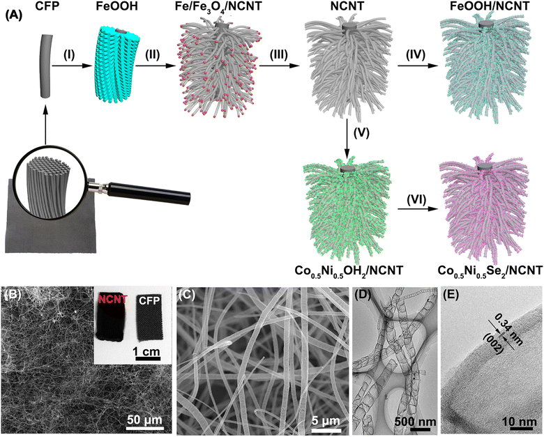
Fig. 1A depicts the formation process of coaxial three-dimensional electrodes. First of all, well-aligned FeOOH short nanorods were uniformly grown on CFP via the hydrolysis of FeCl3 (Step I in Fig. 1A and S1†).40 FeOOH is converted into iron nanocrystals during urea pyrolysis process, and as catalytic sites further initiate the nucleation and growth of NCNT using the pyrolysis products via a chemical vapor deposition (Step II in Fig. 1A).41 It is evidenced by diffraction peaks of iron nanocrystals at 2θ = 43.7° and 63.4° appearing in the XRD pattern (Fig. S2†) and the majority of iron nanoparticles locating at the tip of NCNT (Fig. S3A and B†). The XRD pattern also shows two diffraction peaks at 2θ = 30.1° and 35.4°, which assign to Fe3O4. It is probably because a few iron nanocrystals are likely to oxidize without the protection of carbon layer when exposed to air.42 Photograph and SEM images in Fig. 1B and S3† reveal the dense growth of NCNT array on CFP, and its length depends on the pyrolysis times and can reach several hundred microns after 60 min reaction. During the subsequent acid leaching process, iron species were completely dissolved (Step III in Fig. 1A), as illustrated by the disappearance of the Fe and Fe3O4 phase in the XRD pattern (Fig. S2†). While the bamboo-like structure of NCNT array is well conserved, as displayed by Fig. 1C and D. High-resolution TEM image in Fig. 1E reveals the well-defined lattice fringes at a spacing of 0.34 nm that match to the (002) plane of graphite, indicative of high crystallization and graphitization degrees of NCNT array.Raman and XPS techniques are used to further characterize the graphitization degree and bonding configuration of NCNT. The Raman spectrum in Fig. 2A reveals the graphitic D and G bands at 1355 cm−1 and 1583 cm−1, respectively, with the intensity ratio (ID/IG) close to 1.04, most likely due to oxygen and nitrogen doping into the sp2 carbon structure. It is manifested by the appearance of oxygen and nitrogen signals in XPS spectra (Fig. 2B). The absence of iron signal verifies the complete dissolution of iron species during the acid etching process. The C 1s XPS signal is deconvoluted into three peaks at 285.0 eV, 285.8 eV, and 287.0 eV, which are ascribed to sp2C, C–N and C![[double bond, length as m-dash]](https://www.rsc.org/images/entities/char_e001.gif) O, respectively (Fig. 2C).43 High resolution N 1s XPS spectrum is fitted into four peaks at the binding energies of 398.1 eV, 400.2 eV, 401.4 eV, and 402.7 eV, ascribing to pyridinic, pyrrolic, graphitic, and oxidized N atoms with a percentage of 44.2%, 27.8%, 19.9%, and 8.1%, respectively (Fig. 2D). Low O/C (<1.0%) and N/C (<3.8%) ratios in the NCNT verify a high degree of graphitization degree, making it a promising three-dimensional scaffold.
O, respectively (Fig. 2C).43 High resolution N 1s XPS spectrum is fitted into four peaks at the binding energies of 398.1 eV, 400.2 eV, 401.4 eV, and 402.7 eV, ascribing to pyridinic, pyrrolic, graphitic, and oxidized N atoms with a percentage of 44.2%, 27.8%, 19.9%, and 8.1%, respectively (Fig. 2D). Low O/C (<1.0%) and N/C (<3.8%) ratios in the NCNT verify a high degree of graphitization degree, making it a promising three-dimensional scaffold.
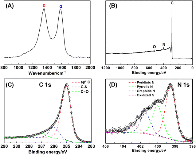 | ||
| Fig. 2 (A) Raman spectrum (B) XPS full spectrum, and (C and D) high resolution C 1s and N 1s XPS spectra of NCNT array. | ||
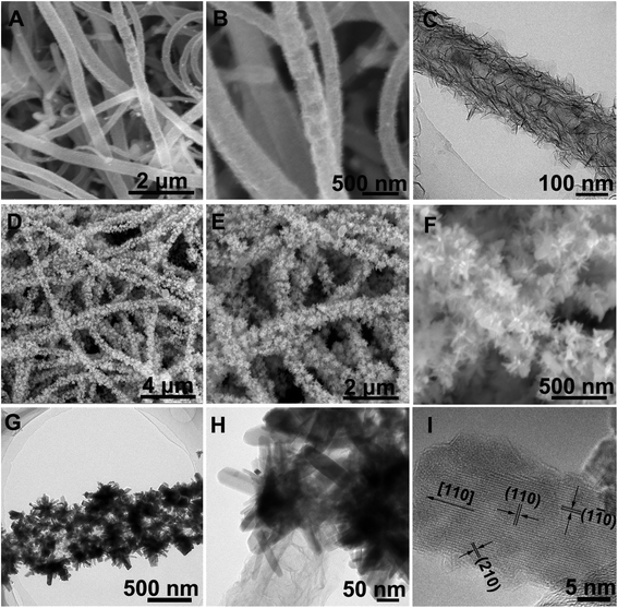
Using NCNT array as a scaffold, electrochemically active components, such as, Co0.5Ni0.5(OH)2, Co0.5Ni0.5Se2, and FeOOH, were deposited at the surface to form the coaxial structure. As seen from Fig. 3A–C and Step IV in Fig. 1A, the thin Co0.5Ni0.5(OH)2 nanosheets were uniformly grown at the NCNT using a mixture of CoCl2 and NiCl2 (Co/Ni = 1![[thin space (1/6-em)]](https://www.rsc.org/images/entities/char_2009.gif) :
:![[thin space (1/6-em)]](https://www.rsc.org/images/entities/char_2009.gif) 1) solution, resulting in forming the coaxial Co0.5Ni0.5(OH)2/NCNT array.9,36 The Co0.5Ni0.5(OH)2 loading in the coaxial array increases by a factor of >3 as compared to that directly deposited on carbon fiber paper, which is probably ascribed to larger surface area (38.0 m2 g−1) of NCNT array than that (9.8 m2 g−1) for carbon fiber paper (Fig. S4†). After a selenization process, Co0.5Ni0.5(OH)2 component in the coaxial array are converted into the selenides, which is demonstrated by the diffraction peaks agreeing well with that of CoSe2 (JCPDS 00-029-1417, Fig. S5†). The X-ray fluorescence (XRF) confirms the co-existence of Co and Ni species in the Co0.5Ni0.5Se2/NCNT with a Co/Ni and (Co + Ni)/Se ratio of 0.96 and 0.51, in well agreement with that in the reactants and chemical formula of CoSe2. As displayed by SEM images (Fig. 3D and E), Co0.5Ni0.5Se2/NCNT also displays the coaxial array structure. However, distinguished from thin Co0.5Ni0.5(OH)2 nanosheets in Co0.5Ni0.5(OH)2/NCNT, flower-like Co0.5Ni0.5Se2 in Co0.5Ni0.5Se2/NCNT is composed of short nanorods (Fig. 3F–H). High-resolution TEM image in Fig. 3I shows the short nanorods grow along the [110] direction. The Co0.5Ni0.5(OH)2 nanosheets and Co0.5Ni0.5Se2 nanorods are also explored for being grown at carbon fiber paper via a similar process with Co0.5Ni0.5(OH)2/NCNT and Co0.5Ni0.5Se2/NCNT (Fig. S6†). In addition, the FeOOH component with a mass loading of 3.0 mg cm−2 is deposited at the NCNT array scaffold to produce the coaxial array structure (Step VI in Fig. 1A, S7 and S8†), when the deposition time is 20 min.
1) solution, resulting in forming the coaxial Co0.5Ni0.5(OH)2/NCNT array.9,36 The Co0.5Ni0.5(OH)2 loading in the coaxial array increases by a factor of >3 as compared to that directly deposited on carbon fiber paper, which is probably ascribed to larger surface area (38.0 m2 g−1) of NCNT array than that (9.8 m2 g−1) for carbon fiber paper (Fig. S4†). After a selenization process, Co0.5Ni0.5(OH)2 component in the coaxial array are converted into the selenides, which is demonstrated by the diffraction peaks agreeing well with that of CoSe2 (JCPDS 00-029-1417, Fig. S5†). The X-ray fluorescence (XRF) confirms the co-existence of Co and Ni species in the Co0.5Ni0.5Se2/NCNT with a Co/Ni and (Co + Ni)/Se ratio of 0.96 and 0.51, in well agreement with that in the reactants and chemical formula of CoSe2. As displayed by SEM images (Fig. 3D and E), Co0.5Ni0.5Se2/NCNT also displays the coaxial array structure. However, distinguished from thin Co0.5Ni0.5(OH)2 nanosheets in Co0.5Ni0.5(OH)2/NCNT, flower-like Co0.5Ni0.5Se2 in Co0.5Ni0.5Se2/NCNT is composed of short nanorods (Fig. 3F–H). High-resolution TEM image in Fig. 3I shows the short nanorods grow along the [110] direction. The Co0.5Ni0.5(OH)2 nanosheets and Co0.5Ni0.5Se2 nanorods are also explored for being grown at carbon fiber paper via a similar process with Co0.5Ni0.5(OH)2/NCNT and Co0.5Ni0.5Se2/NCNT (Fig. S6†). In addition, the FeOOH component with a mass loading of 3.0 mg cm−2 is deposited at the NCNT array scaffold to produce the coaxial array structure (Step VI in Fig. 1A, S7 and S8†), when the deposition time is 20 min.
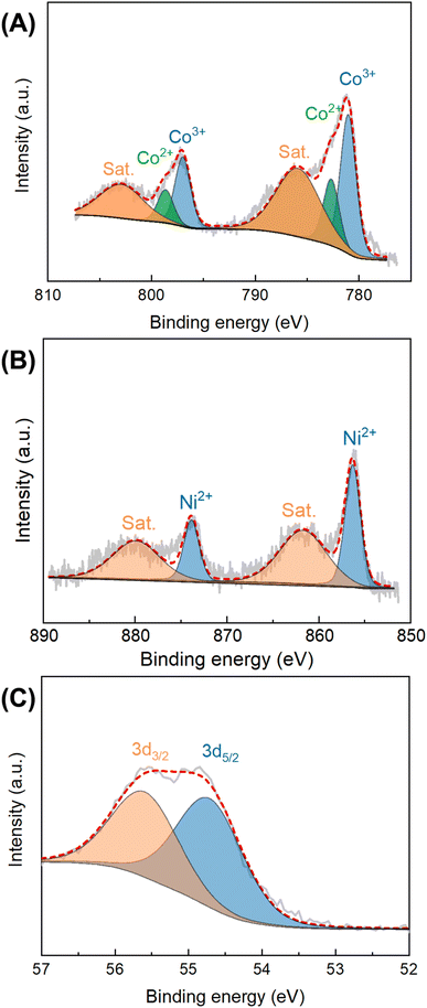
The chemical composition and bonding configuration of Co0.5Ni0.5Se2/NCNT were investigated by using XPS technology. The XPS signals in Fig. S9† suggest the existence of Co, Ni, Se, C, N, and O species in Co0.5Ni0.5Se2/NCNT. High resolution Co 2p XPS spectra display four peaks at 781.0 eV, 782.7 eV, 797.0 eV, and 798.7 eV, which are attributed to the 2p3/2 signals for Co3+ and Co2+ and the 2p1/2 signals for Co3+ and Co2+, respectively.44 The additional two peaks located at 785.9 eV and 802.9 eV assign to the satellite peaks of Co 2p3/2 and Co 2p1/2, respectively. The peaks at binding energies of 856.3 eV and 873.9 eV in Ni 2p XPS signals belong to Ni2+ 2p3/2 and Ni2+ 2p1/2, respectively (Fig. 4B).45 The corresponding satellite peaks locate at 861.7 eV and 879.9 eV. In Se 3d XPS signals, the peaks at 54.8 eV and 55.7 eV are the Se 3d spin-orbits (3d5/2 and Se 3d3/2) of metal–selenium bond (Fig. 4D).46 The O 1s, C 1s, and N 1s fine XPS signals of Co0.5Ni0.5Se2/NCNT verify that carbon, nitrogen, and oxygen species originate from NCNT and carbon fiber paper components (Fig. S10–S12†), and show the similar environments with that for NCNT array.
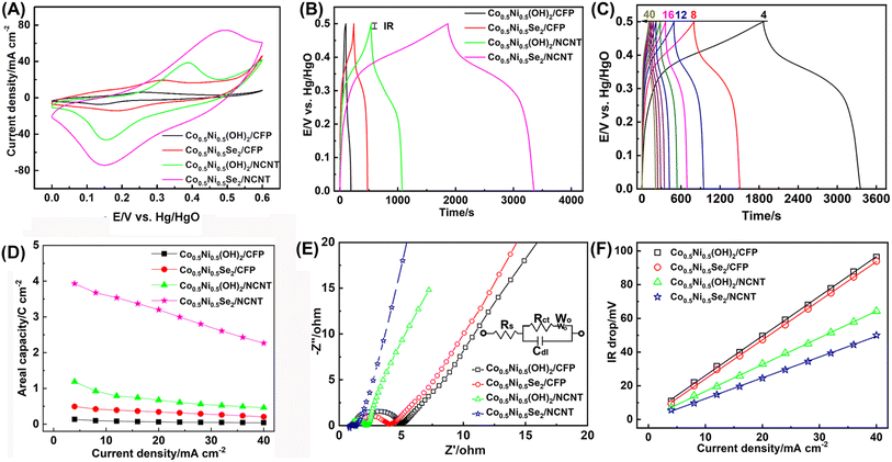
The electrochemical properties of Co0.5Ni0.5Se2/NCNT were tested in a typical three electrode configuration. The Co0.5Ni0.5(OH)2/CFP, Co0.5Ni0.5Se2/CFP, and Co0.5Ni0.5(OH)2/NCNT electrodes are given for comparison. As depicted by Fig. 5A, they all have a pair of redox peak corresponding to the redox reaction of Co2+/Co3+ and Ni2+/Ni3+. The nonlinear galvanostatic charge/discharge curves in Fig. 5B further suggest a faradaic process during discharging/charging, which is difference from quasi-rectangular CV curve and linear galvanostatic charge/discharge curve for NCNT array scaffold mainly contributed by electrical double layer capacitance (Fig. S13†). Note that the discharge time follows the order of Co0.5Ni0.5(OH)2/CFP < Co0.5Ni0.5Se2/CFP < Co0.5Ni0.5(OH)2/NCNT < Co0.5Ni0.5Se2/NCNT at 4 mA cm−2. An areal capacity at 4 mA cm−2 is 3.9 C cm−2 for Co0.5Ni0.5Se2/NCNT and 1.2 C cm−2 for Co0.5Ni0.5(OH)2/NCNT, which are two order of magnitude higher than NCNT array scaffold (21.0 mC cm−2). It reveals the capacity of the coaxial array electrodes mainly originates from battery-type charge storage of Co0.5Ni0.5(OH)2 and Co0.5Ni0.5Se2 materials rather than capacitive charge storage of NCNT array scaffold. Moreover, the coaxial array electrodes have over 7 times higher areal capacity than 0.5 C cm−2 for Co0.5Ni0.5Se2/CFP and 0.1 C cm−2 for Co0.5Ni0.5(OH)2/CFP, probably due to large surface area and good electric conductivity of NCNT array scaffold. Fig. 5C shows the charge/discharge profiles of Co0.5Ni0.5Se2/NCNT at 4–40 mA cm−2, of which the symmetric character implies good rate capability. It is consolidated by the high retention rate of the areal capacity when increasing the discharge current from 4 mA cm−2 to 40 mA cm−2 (Fig. 5D), where 57.6% of the capacity is preserved for Co0.5Ni0.5Se2/NCNT, in contrast to 39.0% for Co0.5Ni0.5(OH)2/NCNT, 41.2% for Co0.5Ni0.5Se2/CFP, and 29.3% for Co0.5Ni0.5(OH)2/CFP.
Note that a specific capacity of about 280 C g−1 at ∼5 A g−1 is achieved for Co0.5Ni0.5(OH)2/NCNT, much higher than 168 C g−1 for Co0.5Ni0.5(OH)2/CFP, may since NCNT array with large surface area and hierarchical structure promote the exposure of active component to the electrolyte and rapid ion/electron transport. When Co0.5Ni0.5Se2 component replaced of Co0.5Ni0.5(OH)2 in the coaxial array electrode, the specific capacity shows a notable increase and approaches to over 650 C g−1 and 411 C g−1 for Co0.5Ni0.5Se2/NCNT at ∼1 A g−1 and 5 A g−1, respectively (Fig. S14†), suggesting better electrochemical performance of Co0.5Ni0.5Se2 than Co0.5Ni0.5(OH)2. Moreover, the specific capacity of Co0.5Ni0.5Se2/NCNT stands the top level among the best-performing nickel cobalt selenide electrodes reported recently (Table S1†). The good long-term stability performance of Co0.5Ni0.5Se2/NCNT is demonstrated by low to 5.9% of the initial capacity loss when being repetitively charged/discharged at 20 mA cm−2 for 5000 cycles (Fig. S15†), in contrast to 11.6% loss for Co0.5Ni0.5Se2/CFP, 12.9 loss for Co0.5Ni0.5(OH)2/NCNT, and 39.7% for Co0.5Ni0.5(OH)2/CFP.
The coaxial Co0.5Ni0.5Se2/NCNT array electrode exhibits an impressive electrochemical performance, which is attributed to three factors listed below. First of all, large surface area and porous features of NCNT array are favorable for loading more active components, such as, 0.8 mg cm−2 for Co0.5Ni0.5(OH)2/CFP, 2.7 mg cm−2 for Co0.5Ni0.5(OH)2/NCNT, 1.8 mg cm−2 for Co0.5Ni0.5Se2/CFP, and 5.5 mg cm−2 for Co0.5Ni0.5Se2/NCNT, and thus increase the areal capacity. Secondly, it is evidenced that the charge storage has nothing to do with selenium species and instead results from rich Co2+/Co3+ and Ni2+/Ni3+ redox reactions.11 Therefore, the higher electrochemical activity and electric conductivity of the selenides than hydroxides lead to the improved charge storage performance. Thirdly, NCNT array scaffold promotes rapid electron/ion transport, as seen from electrochemical impedance spectroscopy (EIS) and equivalent series resistance (ESR). EIS curves in Fig. 5E reveal that the charge transfer resistance (Rct) reduce from 2.01 ohm for Co0.5Ni0.5Se2/CFP to 0.27 ohm for Co0.5Ni0.5Se2/NCNT, and 3.28 ohm for Co0.5Ni0.5(OH)2/CFP to 1.15 ohm for Co0.5Ni0.5(OH)2/NCNT. The ESR derived from the curves of Vdrop versus current density agree well with the EIS results (Fig. 5F), suggesting faster electron and ion transport characteristics of the coaxial array electrode, in comparison with Co0.5Ni0.5(OH)2 and Co0.5Ni0.5Se2 components directly grown on carbon fiber paper.
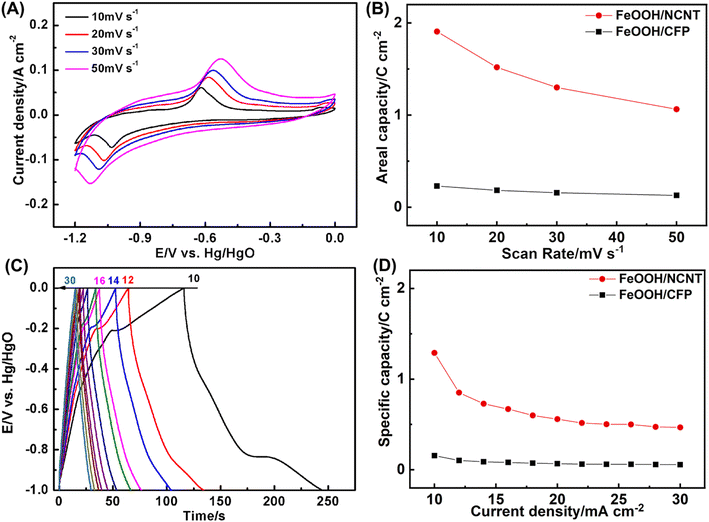
Fig. 6 depicts the electrochemical performance of the coaxial FeOOH/NCNT array electrode performed in a three-electrode configuration. As depicted in Fig. 6A, a pair of redox peak appears in the CV curves at the potential range of −1.2–0.0 V vs. Hg/HgO, which belongs to the conversion of Fe3+/Fe2+. The capacity calculated according to CV curves is 1.90 C cm−2 at 10 mV s−1 and 1.06 F cm−2 at 50 mV s−1 (Fig. 6B), which increase by a factor of ∼8 as compared to the FeOOH/CFP electrode. Fig. 6C shows galvanostatic charge/discharge curves in the voltage window of 1.0 V.47–49 The capacity reaches 1.29 C cm−2 for FeOOH/NCNT at 10 mA cm−2. Despite a significant drop when the discharge current is increased to 30 mA cm−2, the capacity of FeOOH/NCNT is still substantially larger than that of FeOOH/CFP, further illustrating the improved electrochemical performance of the coaxial array electrode.
In views of good electrochemical performance of the coaxial array electrodes, a cell with the thickness of 0.08 cm was assembled by using Co0.5Ni0.5Se2/NCNT positive electrode and FeOOH/NCNT negative electrode. CV curves in Fig. 7A reveal that Co0.5Ni0.5Se2/NCNT//FeOOH/NCNT cell can stably scan from 0 V to 1.6 V at a scan rate of 10–50 mV s−1 (Fig. 7A), as evidenced by the successful charge/discharge in the potential of 0–1.6 V (Fig. 7B), suggesting the voltage window extending to 1.6 V. Fig. 7C shows a specific capacity of Co0.5Ni0.5Se2/NCNT//FeOOH/NCNT cell at 4–20 mA cm−2. The capacity approaches to 1.8 C cm−2 (0.5 mA h cm−2 and 207.2 C g−1) and 22.5 C cm−3 at 4 mA cm−2, respectively. Even when the discharge current is increased to 20 mA cm−2, the cell still exports a capacity of 1.0 C cm−2 (0.3 mA h cm−2 and 114.8 C g−1) and 12.5 C cm−3. The capacity is comparable to, if not better than, those of previously reported nickel cobalt selenide-based energy storage devices including (Ni, Co)0.85Se//porous graphene (0.95 C cm−2 at 1 mA cm−2),50 (Ni0.1Co0.9)9S8@NF//rGO@NF (42.6 C g−1 at 0.2 A g−1),20 H–NiCoSe2//AC (168 C g−1 at 0.2 A g−1),51 CoNiSe2/CoNiSe2//CoNiO2/CoNiO2 (16.2 C cm−3 at 50.9 mA cm−3),52 (Ni, Co)Se2/NiCo-LDH//porous carbon (163.2 C g−1 at 2 A g−1),53 NiCo2Se4//BiSe (308.7 C g−1 at 2 A g−1),54 Ni4.5Co4.5-Se/NPCC//Fe3C/CF (113.7 C g−1 at 1 A g−1),55 NiSe2/CoSe2//N, S-rGO (257.5 C g−1 at 0.5 A g−1),56 etc. The long-term durability is examined via the repetitive charge–discharge process at 10 mA cm−2. As depicted by Fig. 7D, the capacity shows no decline in the initial 5000 cycles. Merely 14.0% of the capacity is lost even after 10![[thin space (1/6-em)]](https://www.rsc.org/images/entities/char_2009.gif) 000 repetitive cycles, which is probably due to the component transformation from the selenide to hydroxide and poor electric conductivity of FeOOH component.
000 repetitive cycles, which is probably due to the component transformation from the selenide to hydroxide and poor electric conductivity of FeOOH component.
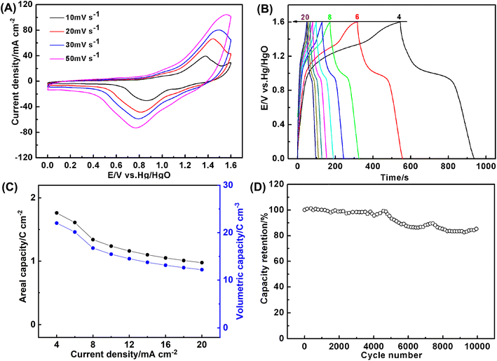 | ||
| Fig. 7 (A) CV curves (B) the galvanostatic charge/discharge curves, (C) the areal and volumetric capacity, and (D) long-term cycling stability at 10 mA cm−2 of Co0.5Ni0.5Se2/NCNT//FeOOH/NCNT cell. | ||
Ragone plot in Fig. 8 shows energy and power density of Co0.5Ni0.5Se2/NCNT//FeOOH/NCNT cell. It delivers a volumetric energy density of 4.9 mW h cm−3 (0.4 mW h cm−2) at 44.8 mW cm−3 (3.6 mW cm−2) and still retains at 2.7 mW h cm−3 (0.4 mW h cm−2) even at a high power density of 208.1 mW cm−3 (16.6 mW cm−2). The unexpected energy storage performance, particularly at high power density, is attributed to not only the good electrochemical activity of nickel cobalt selenide component but also the high mass loading and fast ion/electron transport behavior contributed by the coaxial array structure. Moreover, the performance of Co0.5Ni0.5Se2/NCNT//FeOOH/NCNT cell surpasses many best-performing energy storage devices reported before, such as, Ni0.34Co0.66Se2//Ni0.34Co0.66Se2 (0.47 mW h cm−3),57 H-TiO2@MnO2//H-TiO2@C (0.30 mW h cm−3),58 MnO2//oxygen-deficient Fe2O3 (0.35 mW h cm−3),59 MnO2//Bi2O3 (43.4 μW h cm−2),60 MnO2//Fe2O3 (0.32 mW h cm−3),61 Co9S8//Co3O4@RuO2 (1.44 mW h cm−3),62 and ZnO@MnO2//graphene (0.234 mW h cm−3),63 (Ni, Co)0.85Se//porous graphene (2.85 mW h cm−3),50 CuSe@MnOOH//CuSe@FeOOH (2.9 μW h cm−3),52 etc. The gravimetric energy density of Co0.5Ni0.5Se2/NCNT//FeOOH/NCNT cell approximately reaches 46.1 W h kg−1 at 421.7 W kg−1 and 25.5 W h kg−1 at 1958.4 W kg−1, depending on active component mass, which also stand at the top level among the state-of-the-art nickel cobalt selenides-based cells including Ni4.5Co4.5-Se/NPCC//Fe3C/CF (47.4 W h kg−1 at 1.5 kW kg−1),64 (Ni, Co)Se2/NiCo-LDH//porous carbon (39 W h kg−1 at 1650 W kg−1),53 H-NiCoSe2//AC (35 W h kg−1 at 188 W kg−1),51 etc.
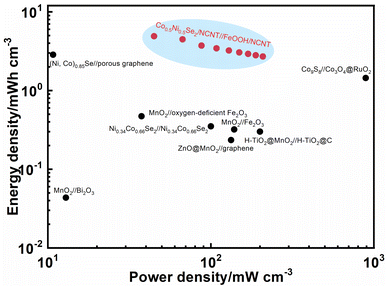 | ||
| Fig. 8 Ragone plot of Co0.5Ni0.5Se2/NCNT//FeOOH/NCNT cell. The performances of the similar energy storage devices reported before were added for comparison. | ||
Conclusion
In summary, we have developed a one-step urea pyrolysis approach to synthesize a highly crystalline NCNT array that serves as a potential scaffold for constructing the coaxial array electrodes. The coaxial array electrodes with the characteristics of large surface area, good electric conductivity, and short ion diffusion pathway exhibited the significantly enhanced electrochemical performance compared to that directly loaded on carbon fiber paper. Moreover, nickel cobalt selenide is demonstrated to exhibit better electrochemical activity than the hydroxide counterpart. Combined with the character of the coaxial array structure and exceptional activity of nickel cobalt selenide, the cell composed of Co0.5Ni0.5Se2/NCNT and FeOOH/NCNT electrodes with a voltage window of 1.6 V exports a maximum volumetric energy density of 4.9 mW h cm−3 and can be stably operated for 10![[thin space (1/6-em)]](https://www.rsc.org/images/entities/char_2009.gif) 000 cycles. This work provides a facile method for preparing three-dimensional coaxial array electrode with an unprecedent electrochemical performance.
000 cycles. This work provides a facile method for preparing three-dimensional coaxial array electrode with an unprecedent electrochemical performance.
Conflicts of interest
There are no conflicts to declare.References
- P. G. Bruce, B. Scrosati and J. M. Tarascon, Angew. Chem., Int. Ed., 2008, 47, 2930–2946 CrossRef CAS PubMed
.
- B. E. Conway, Electrochemical Supercapacitors. Scientific Fundamentals and Technological Application, Plenum, New York, 1999 Search PubMed
.
- J. Zhao and A. F. Burke, Energy Storage Mater., 2021, 36, 31–55 CrossRef
.
- G. Z. Chen, Int. Mater. Rev., 2017, 62, 173–202 CrossRef CAS
.
- M. Khalid, N. Arshid and N. Grace, Advances in Supercapacitor and Supercapattery: Innovations in Energy Storage Devices, Elsevier Science, 2020 Search PubMed
.
- A. Das, B. Raj, M. Mohapatra, S. M. Andersen and S. Basu, Wiley Interdiscip. Rev.: Energy Environ., 2022, 11, e414 CAS
.
- K. Zhang, X. Han, Z. Hu, X. Zhang, Z. Tao and J. Chen, Chem. Soc. Rev., 2015, 44, 699–728 RSC
.
- Y. Gao and L. Zhao, Chem. Eng. J., 2022, 430, 132745 CrossRef CAS
.
- J. Xiao, L. Wan, S. Yang, F. Xiao and S. Wang, Nano Lett., 2014, 14, 831–838 CrossRef CAS PubMed
.
- D. Chen, Z. Zhao, G. Chen, T. Li, J. Chen, Z. Ye and J. Lu, Coord. Chem. Rev., 2023, 479, 214984 CrossRef CAS
.
- G. Tang, J. Liang and W. Wu, Adv. Funct. Mater., 2024, 34, 2310399 CrossRef CAS
.
- C. Lamiel, I. Hussain, H. Rabiee, O. R. Ogunsakin and K. Zhang, Coord. Chem. Rev., 2023, 480, 215030 CrossRef CAS
.
- Z. Xie, D. Qiu, J. Xia, J. Wei, M. Li, F. Wang and R. Yang, ACS Appl. Mater. Interfaces, 2021, 13, 12006–12015 CrossRef CAS PubMed
.
- C. Miao, C. Zhou, H.-E. Wang, K. Zhu, K. Ye, Q. Wang, J. Yan, D. Cao, N. Li and G. Wang, J. Power Sources, 2021, 490, 229532 CrossRef CAS
.
- F. Ma, J. Lu, L. Pu, W. Wang and Y. Dai, J. Colloid Interface Sci., 2020, 563, 435–446 CrossRef PubMed
.
- Y. Liu, W. Li, X. Chang, H. Chen, X. Zheng, J. Bai and Z. Ren, J. Colloid Interface Sci., 2020, 562, 483–492 CrossRef CAS PubMed
.
- T. T. Nguyen, J. Balamurugan, V. Aravindan, N. H. Kim and J. H. Lee, Chem. Mater., 2019, 31, 4490–4504 CrossRef CAS
.
- C. Miao, P. Xu, J. Zhao, K. Zhu, K. Cheng, K. Ye, J. Yan, D. Cao, G. Wang and X. Zhang, ACS Appl. Energy Mater., 2019, 2, 3595–3604 CrossRef CAS
.
- Y. Ma, C. Hou, H. Zhang, Q. Zhang, H. Liu, S. Wu and Z. Guo, Electrochim. Acta, 2019, 315, 114–123 CrossRef CAS
.
- P. Yang, Z. Wu, Y. Jiang, Z. Pan, W. Tian, L. Jiang and L. Hu, Adv. Energy Mater., 2018, 8, 1801392 CrossRef
.
- X. Song, C. Huang, Y. Qin, H. Li and H. C. Chen, J. Mater. Chem. A, 2018, 6, 16205–16212 RSC
.
- L. Quan, T. Liu, M. Yi, Q. Chen, D. Cai and H. Zhan, Electrochim. Acta, 2018, 281, 109–116 CrossRef CAS
.
- T. Chen, S. Li, J. Wen, P. Gui, Y. Guo, C. Guan, J. Liu and G. Fang, Small, 2018, 14, 1700979 CrossRef
.
- A. Chang, C. Zhang, Y. Yu, Y. Yu and B. Zhang, ACS Appl. Mater. Interfaces, 2018, 10, 41861–41865 CrossRef CAS
.
- L. Du, W. Du, H. Ren, N. Wang, Z. Yao, X. Shi, B. Zhang, J. Zai and X. Qian, J. Mater. Chem. A, 2017, 5, 22527–22535 RSC
.
- B. L. Ellis, P. Knauth and T. Djenizian, Adv. Mater., 2014, 26, 3368–3397 CrossRef CAS
.
- T. S. Arthur, D. J. Bates, N. Cirigliano, D. C. Johnson, P. Malati, J. M. Mosby, E. Perre, M. T. Rawls, A. L. Prieto and B. Dunn, MRS Bull., 2011, 36, 523–531 CrossRef CAS
.
- X. Lang, A. Hirata, T. Fujita and M. Chen, Nat. Nanotechnol., 2011, 6, 232–236 CrossRef CAS PubMed
.
- N. Swain, A. Mitra, B. Saravanakumar, S. K. Balasingam, S. Mohanty, S. K. Nayak and A. Ramadoss, Electrochim. Acta, 2020, 342, 136041 CrossRef CAS
.
- J. Kang, A. Hirata, H. J. Qiu, L. Chen, X. Ge, T. Fujita and M. Chen, Adv. Mater., 2014, 26, 269–272 CrossRef CAS PubMed
.
- D. Pei, J. Bao, Y. Li, Y. Li, H. Wang, H. Lu and Z. Wang, J. Energy Storage, 2022, 51, 104483 CrossRef
.
- Z. Xu, C. Du, H. Yang, J. Huang, X. Zhang and J. Chen, Chem. Eng. J., 2021, 421, 127871 CrossRef CAS
.
- X. Lv, L. Feng, X. Lin and Y. Ni, J. Energy Storage, 2022, 47, 103579 CrossRef
.
- D. Cai, J. Du, C. Zhu, Q. Cao, L. Huang, J. Wu, D. Zhou, Q. Xia, T. Chen, C. Guan and Y. Xia, ACS Appl. Energy Mater., 2020, 3, 12162–12171 CrossRef CAS
.
- C. Liu, Y. Bai, W. Li, F. Yang, G. Zhang and H. Pang, Angew. Chem., Int. Ed., 2022, 61, e202116282 CrossRef CAS PubMed
.
- L. Wan, J. Xiao, F. Xiao and S. Wang, ACS Appl. Mater. Interfaces, 2014, 6, 7735–7742 CrossRef CAS PubMed
.
- B. Huang, H. Wang, S. Liang, H. Qin, Y. Li, Z. Luo, C. Zhao, L. Xie and L. Chen, Energy Storage Mater., 2020, 32, 105–114 CrossRef
.
- J. Jiang, Y. Hu, X. He, Z. Li, F. Li, X. Chen, Y. Niu, J. Song, P. Huang, G. Tian and C. Wang, Small, 2021, 17, 2102565 CrossRef CAS PubMed
.
- J. Iqbal, A. Numan, S. Rafique, R. Jafer, S. Mohamad, K. Ramesh and S. Ramesh, Electrochim. Acta, 2018, 278, 72–82 CrossRef CAS
.
- L. Vayssieres, N. Beermann, S. E. Lindquist and A. Hagfeldt, Chem. Mater., 2001, 13, 233–235 CrossRef CAS
.
- X. Huang, R. Farra, R. Schlögl and M. G. Willinger, Nano Lett., 2019, 19, 5380–5387 CrossRef CAS PubMed
.
- H. Li, J. Wan, Y. Ma and Y. Wang, Chem. Eng. J., 2016, 301, 315–324 CrossRef CAS
.
- D. C. Wei, Y. Q. Liu, Y. Wang, H. L. Zhang, L. P. Huang and G. Yu, Nano Lett., 2009, 9, 1752–1758 CrossRef CAS PubMed
.
- T. Liu, Y. Yang, S. Cao, R. Xiang, L. Zhang and J. Yu, Adv. Mater., 2023, 35, 2207752 CrossRef CAS PubMed
.
- Y. Han, H. Li, M. Zhang, Y. Fu, Y. Liu, Y. Yang, J. Xu, Y. Geng and L. Wang, Appl. Surf. Sci., 2019, 495, 143606 CrossRef CAS
.
- D. Susac, A. Sode, L. Zhu, P. C. Wong, M. Teo, D. Bizzotto, K. A. R. Mitchell, R. R. Parsons and S. A. Campbell, J. Phys. Chem. B, 2006, 110, 10762–10770 CrossRef CAS PubMed
.
- R. B. Pujari, S. J. Patil, J. Park, A. Shanmugasundaram and D. W. Lee, J. Power Sources, 2019, 436, 226826 CrossRef CAS
.
- R. Barik, B. K. Jena and M. Mohapatra, RSC Adv., 2017, 7, 49083–49090 RSC
.
- S. Yang, X. Song, P. Zhang, J. Sun and L. Gao, Small, 2014, 10, 2270–2279 CrossRef CAS
.
- C. Xia, Q. Jiang, C. Zhao, P. M. Beaujuge and H. N. Alshareef, Nano Energy, 2016, 24, 78–86 CrossRef CAS
.
- L. Hou, Y. Shi, C. Wu, Y. Zhang, Y. Ma, X. Sun, J. Sun, X. Zhang and C. Yuan, Adv. Funct. Mater., 2018, 28, 1705921 CrossRef
.
- Q. Wang, X. Tian and D. Zhang, Mater. Lett., 2020, 276, 128245 CrossRef CAS
.
- X. Li, H. Wu, C. Guan, A. M. Elshahawy, Y. Dong, S. J. Pennycook and J. Wang, Small, 2019, 15, 1803895 CrossRef PubMed
.
- J. Xia, L. Zhang, S. Xuan, Y. Ni and L. Zhang, CrystEngComm, 2022, 24, 2159–2170 RSC
.
- C. Wang, Z. Song, H. Wan, X. Chen, Q. Tan, Y. Gan, P. Liang, J. Zhang, H. Wang, Y. Wang, X. Peng, P. A. van Aken and H. Wang, Chem. Eng. J., 2020, 400, 125955 CrossRef CAS
.
- X. Yun, T. Lu, R. Zhou, Z. Lu, J. Li and Y. Zhu, Chem. Eng. J., 2021, 426, 131328 CrossRef CAS
.
- P. Xu, W. Zeng, S. Luo, C. Ling, J. Xiao, A. Zhou, Y. Sun and K. Liao, Electrochim. Acta, 2017, 241, 41–49 CrossRef CAS
.
- X. Lu, M. Yu, G. Wang, T. Zhai, S. Xie, Y. Ling, Y. Tong and Y. Li, Adv. Mater., 2013, 25, 267–272 CrossRef CAS PubMed
.
- X. Lu, Y. Zeng, M. Yu, T. Zhai, C. Liang, S. Xie, M.-S. Balogun and Y. Tong, Adv. Mater., 2014, 26, 3148–3155 CrossRef CAS PubMed
.
- H. Xu, X. Hu, H. Yang, Y. Sun, C. Hu and Y. Huang, Adv. Energy Mater., 2015, 5, 1401882 CrossRef
.
- P. Yang, Y. Ding, Z. Lin, Z. Chen, Y. Li, P. Qiang, M. Ebrahimi, W. Mai, C. P. Wong and Z. L. Wang, Nano Lett., 2014, 14, 731–736 CrossRef CAS PubMed
.
- J. Xu, Q. Wang, X. Wang, Q. Xiang, B. Liang, D. Chen and G. Shen, ACS Nano, 2013, 7, 5453–5462 CrossRef CAS PubMed
.
- Z. Wang, Z. Zhu, J. Qiu and S. Yang, J. Mater. Chem. C, 2014, 2, 1331–1336 RSC
.
- X. Sheng, T. Li, M. Sun, G. Liu, Q. Zhang, Z. Ling, S. Gao, F. Diao, J. Zhang, F. Rosei and Y. Wang, Electrochim. Acta, 2022, 407, 139892 CrossRef CAS
.
Footnote |
| † Electronic supplementary information (ESI) available. See DOI: https://doi.org/10.1039/d3ra08635f |
| This journal is © The Royal Society of Chemistry 2024 |

