 Open Access Article
Nanofibrous electrospun scaffold doped with hydroxyapatite derived from sand lobster shell (Panulirus homarus) for bone tissue engineering
I Kadek Hariscandra Dinatha a,
Arian H. Diputraa,
Hevi Wihadmadyatamib,
Juliasih Partinia and
Yusril Yusuf
 *a
*a
aDepartment of Physics, Faculty of Mathematics and Natural Science, Universitas Gadjah Mada, Yogyakarta, Indonesia. E-mail: yusril@ugm.ac.id
bDepartment of Anatomy, Faculty of Veterinary Medicine, Universitas Gadjah Mada, Yogyakarta, Indonesia
First published on 11th March 2024
Abstract
Healing of significant segmental bone defects remains a challenge, and various studies attempt to make materials that mimic bone structures and have biocompatibility, bioactivity, biodegradability, and osteoconductivity to native bone tissues. In this work, a nanofiber scaffold membrane of polyvinyl alcohol (PVA)/polyvinylpyrrolidone (PVP)/chitosan (CS) combined with hydroxyapatite (HAp) from sand lobster (SL; Panulirus homarus) shells, as a calcium source, was successfully synthesized to mimic the nanoscale extracellular matrix (ECM) in the native bone. The HAp from SL shells was synthesized by co-precipitation method with Ca/P of 1.67 and incorporated into the nanofiber membrane PVA/PVP/CS synthesized by the electrospinning method with varying concentrations, i.e. 0, 1, 3, and 5% (w/v). Based on the morphological and physicochemical analysis, the addition of HAp into the nanofiber successfully showed incorporation into the nanofiber with small agglomeration at HAp concentrations of 1, 3, and 5% (w/v). This led to a smaller fiber diameter with higher concentration of Hap, and incorporating HAp into the nanofiber could improve the mechanical properties of the nanofiber closer to the trabecula bone. Moreover, in general, swelling due to water absorption increases due to higher hydrophilicity at higher HAp concentrations and leads to the improvement of the degradation process and protein adsorption of the nanofiber. Biomineralization in a simulated body fluid (SBF) solution confirms that the HAp in the nanofiber increases bioactivity, and it can be seen that more apatite is formed during longer immersion in the SBF solution. The nanofiber PVA/PVP/CS HAp 5% has the most potential for osteoblast (MC3T3E1) cell viability after being incubated for 24 h, and it allowed the cell to attach and proliferate. Additionally, the higher HAp concentration in the nanofiber scaffold membrane can significantly promote the osteogenic differentiation of MC3T3E1 cells. Overall, the PVA/PVP/CS/HAp 5% nanofiber scaffold membrane has the most potential for bone tissue engineering.
1. Introduction
The human body comprises bones, which are the hard tissues forming the skeleton to support passive movement.1 Similar to any other tissues, bones can sustain harm from trauma, traffic accidents, fracture nonunion, bone tumour resection, or degenerative diseases such as osteoporosis.2,3 Despite the unique ability of bones to heal and regenerate, the bone itself cannot repair large segmental bone defects.2,4 Due to the scarcity of bone materials to cover the defect and promote bone growth, segmental bone defects remain challenging to heal.5 Various studies have attempted to make materials to mimic bone structures with biocompatibility, bioactivity, biodegradability, and osteoconductivity to bone tissues. There has long been interest in using material scaffolds that consist of bioceramic and polymer components to facilitate the formation of bone cells and tissues.3 Hence, constructing and developing an appropriate scaffold to promote bone formation is the main task in bone tissue engineering.At the nanoscale, the bone forms an extracellular matrix (ECM) that consists of organic minerals (type I collagen) and is reinforced by inorganic minerals (hydroxyapatite (HAp)).6–8 HAp (Ca10(PO4)6(OH)2) is one part of calcium phosphate, which is the main mineral constituent of human bones and teeth.9–11 Since HAp comprises 60–70% of the inorganic mineral content in the human bone,12 bioceramic HAp has biocompatibility, bioactivity, and osteoconductivity to natural bone tissues.13 HAp has two types of crystal structures: monoclinic and hexagonal. The lattice parameters for the monoclinic form are a = 9.421 Å, b = 2a, and c = 6.881 Å, while those for the hexagonal structure are a = b = 9.432 Å and c = 6.881 Å, with a Ca/P molar ratio of 1.67 in both.14,15
However, the use of commercial HAp has disadvantages, such as high cost. In the previous study, we successfully developed a new calcium source from biogenic resources to synthesize HAp. The HAp was synthesized by the co-precipitation method and derived from sand lobster (SL; Panulirus homarus) shells, which the lobster molts waste periodically. Using SL shells as calcium sources to synthesize HAp has advantages, namely reducing the SL shell waste and production costs compared to commercial HAp. In addition, these biogenic resources have good sustainability because lobsters have a periodic molting cycle.16,17 Our previous study described the synthesis process through the co-precipitation method, resulting in a hexagonal crystal structure and a Ca/P molar ratio of 1.67.18 The synthesized HAp can be used as a filler in nanofiber scaffold membranes that are expected to enhance the bioactivity properties in the scaffold.19,20
The ECM structure at the nanoscale in the natural bone forms nanofiber structures. The nanofiber scaffold membrane is one of the bone tissue engineering methods used to mimic the ECM structure at the nanoscale in the bone.8 Nanofiber scaffold engineering will create an environment for the cells similar to the host to stimulate the osteoblast cells to bone growth. Various processing techniques (e.g., phase separation, self-assembly, and electrospinning) have been developed to fabricate nanofiber membrane scaffolds for ECM substitutes.21 Among them, the electrospinning method has advantages. It can process various materials (organic polymers, colloidal particles, and composites),22 is cost-effective, and can generate fibers similar to the fibrous structures of native ECM. Electrospun membranes have been extensively used for tissue engineering primarily because an electrospinning process can easily regulate their microstructure.21,23 The ECM-like architecture on the nanofiber scaffold will provide both mechanical support and biological stimulation for cell proliferation, adhesion, and migration.
The blend solution of several polymerics is more commonly used to prepare electrospun polymeric fibers than a single-component polymer solution because it is more likely to have good electospinnability and biological properties.23 In the present study, we have successfully developed a nanofiber scaffold membrane by combining the polymer and ceramic HAp from SL shells. The polymer solution, which consists of polyvinyl alcohol (PVA)/polyvinylpyrrolidone (PVP)/chitosan (CS), was used as a matrix nanofiber membrane. PVA is an environmentally friendly polymer with advantages such as water solubility, biodegradability, biocompatibility, chemical stability, processability, and excellent spinnability.24 PVP is a surfactant polymer because of its advantages, such as being soluble in water and acids, non-toxic, and stable. PVP has been applied in fields such as pharmacy and biomedical.25 Although nanofiber scaffold membranes should have non-toxic properties, they should also have antibacterial activity. CS is a biopolymer derived from the exoskeletons of crustaceans, crabs, and shrimp shells.26 In addition to the fact that CS is expected to give antibacterial activity to the nanofiber scaffold, CS also has a similar structure to the ECM glycosaminoglycans (GAGs) in the bone.27,28 However, CS has drawbacks, such as low solubility. PVP increases the solubility of CS so that CS is more accessible for solvation. Hap is incorporated into the nanofiber with varied concentrations of 0, 1, 3, and 5%. The nanofiber scaffold membrane was characterized using a scanning electron microscope (SEM), X-ray diffraction (XRD), and Fourier transform infrared (FTIR) to identify their physicochemical properties. Then, the mechanical properties were performed to analyze each sample's tensile strength, Young's modulus, and elongation break. We also conducted the in vitro assay, including biomineralization test, swelling ratio, biodegradation, and protein adsorption. In order to determine the biocompatibility of the nanofiber to osteoblast (MC3T3E1) cells, the viability and osteogenic differentiation of MC3T3E1 cells were evaluated in this work. All of the tests reveal that incorporating HAp from SL shells into nanofiber PVA/PVP/CS has the potential to be applied in bone tissue engineering.
2. Experiment methods
2.1. Materials
In this work, HAp derived calcium dihydroxide (Ca(OH)2) from SL shells (Panulirus homarus) as a calcium source from Buleleng, Bali, Indonesia, and phosphate in the form of diamonium hydrogen phosphate ((NH4)2HPO4) purchased from Merck (USA). The controlled pH uses a 3 M ammonium hydroxide (NH4OH) 25% from Merck (USA). The nanofiber was fabricated using PVA (100% hydrolyzed) with a molecular weight of 145.000 purchased from Merck (Germany), CS with medium molecular weight and PVP with a molecular weight of 10.000 purchased from Sigma-Aldrich (USA). Acetic acid (100%) and dimethyl sulfoxide (DMSO) were purchased from Merck (Germany). The paraformaldehyde (Solarbio, China), fetal bovine serum (FBS) and phosphate-buffered saline (PBS) were purchased from Sigma-Aldrich (USA) and the MTT (3-[4,5-dimethylthiazol-2-yl]-2,5-diphenyltetrazolium bromide) from Biobasic (USA). Penicillin–streptomycin, a fungizone, and MEM-α medium were purchased from Gibco (USA) and an ALP kit from Beyotime (China).2.2. Synthesis of HAp
The previous study described the synthesized process of HAp from SL shells.18 Briefly, the SL shells were cleaned, milled, and calcinated at 1000 °C for 6 h to decompose the calcium carbonate (CaCO3) SL shell powder to obtain Ca(OH)2 powder as in eqn (1) and (2). A total of 6 M (NH4)2HPO solution was titrated at a 1 mL min−1 rate to 10 M Ca(OH)2 solution. This concentration was selected to obtain HAp with a Ca/P molar ratio of 1.67, similar to HAp in natural human bone. The pH was controlled at pH 10 by adding 25% 3 M NH4OH. Then, the mixture was stirred constantly at 60 °C to obtain a homogeneous solution. The chemical reaction to form HAp is shown in eqn (3).18 The synthesized HAp was characterized by XRD, FTIR, and SEM-energy dispersive X-ray (EDX).| CaCO3(s) → CaO(s) + CO2(g) | (1) |
| CaO(s) + H2O(l) → Ca(OH)2(s) | (2) |
| 10Ca(OH)2(s) + 6(NH4)2HPO4(s) → Ca10(PO4)6(OH)2(s) + 12NH4OH(l) + 6H2O(l) | (3) |
After aging the solution for 24 h at room temperature, the filtration procedure was carried out. In order to improve the crystallinity, the mixture was dried for 6 h at 100 °C in an oven and then the sintering process for 6 h at 1000 °C. Afterwards, FTIR, XRD, and SEM-EDX were used to characterize HAp. Fig. 1(A) illustrates the basic schematics used to synthesize HAp.
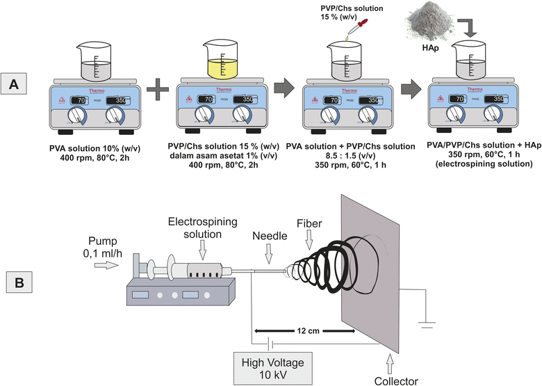 | ||
| Fig. 1 Schematics of the experimental procedure; (A) synthesis of HAp and (B) preparation of the electrospinning solution and experimental setup of the electrospinning process. | ||
2.3. Preparation of the electrospinning solution
PVA was dissolved in distilled water at a concentration of 10% (w/v). A total of 1.4 grams of PVP and 0.1 grams of CS were dissolved in 10 mL acetic acid 1% (v/v), obtaining a 15% (w/v) PVP/CS solution. PVA 10% (w/v) solution was then mixed with PVP/CS 15% (w/v) solution at a ratio of 8.5![[thin space (1/6-em)]](https://www.rsc.org/images/entities/char_2009.gif) :
:![[thin space (1/6-em)]](https://www.rsc.org/images/entities/char_2009.gif) 1.5 (v/v). The mixture was stirred until a homogeneous solution was obtained. Then, HAp was added to the mix with concentrations of 0, 1, 3, and 5% (w/v) with continued stirring until the mixture was homogeneous. More details about the composition of HAp in the electrospinning solution are shown in Table 1. Then, the solution was used for the electrospinning process. The schematic of the electrospinning process is shown in Fig. 1(B).
1.5 (v/v). The mixture was stirred until a homogeneous solution was obtained. Then, HAp was added to the mix with concentrations of 0, 1, 3, and 5% (w/v) with continued stirring until the mixture was homogeneous. More details about the composition of HAp in the electrospinning solution are shown in Table 1. Then, the solution was used for the electrospinning process. The schematic of the electrospinning process is shown in Fig. 1(B).
| No. | Samples name | Samples parameter | ||||
|---|---|---|---|---|---|---|
| PVA (g) | PVP (g) | CS (g) | Solvent (mL) | HAp (g) | ||
| 1 | PVA/PVP/CS/HAp 0% | 1 | 1.4 | 0.1 | 10 | 0 |
| 2 | PVA/PVP/CS/HAp 1% | 1 | 1.4 | 0.1 | 10 | 0.1 |
| 3 | PVA/PVP/CS/HAp 3% | 1 | 1.4 | 0.1 | 10 | 0.3 |
| 4 | PVA/PVP/CS/HAp 5% | 1 | 1.4 | 0.1 | 10 | 0.5 |
2.4. Synthesis of the nanofiber membrane
The prepared solution was put into a 10 mL syringe with a hole diameter of 0.5 mm. A voltage of 10 kV was applied between the tip to the collector covered by aluminum foil with a distance of 12 cm, and the flow rate was automated at 0.1 mL h−1, as shown in Fig. 1(B). The solution was maintained at room temperature. The fiber will be formed at the collector as a nanofiber scaffold membrane PVA/PVP/CS/HAp 0, 1, 3, and 5%. It will be characterized using SEM, XRD, and FTIR.2.5. Physicochemical characterization
FTIR (Thermo Nicolet iS10, Japan) was used to identify the functional groups, bond types, chemical composition, and vibration of molecular bonds in compounds. The analysis was carried out using wavelengths of 4000 cm−1 to 600 cm−1. FTIR was used to identify the functional groups in the SL shell powder, HAp, and nanofiber membranes in this case. We also used FTIR to analyze the apatite mineralization of nanofiber scaffold membranes after soaking in the simulated body fluid (SBF) solution.
 | (4) |
2.6. Antibacterial activity
The antibacterial studies of nanofiber scaffold membranes against E. coli, S. aureus, and P. aeroguosa were performed using the agar well diffusion method with three repetitions. This study evaluated the antibacterial effect of CS on the nanofiber. The antibacterial test was conducted on the nanofiber PVA (as control) and PVA/PVP/CS HAp 0 and 5%. The samples were cut into circular shapes (d = 6 mm) and placed on agar, then the zone of inhibition diameter (ZOI) was measured to assess the antibacterial activity after a 24 h incubation.2.7. In vitro cell experiment
In this work, mouse osteoblast (MC3T3E1) cells were employed. The MTT assay was applied in the cell viability test to determine and evaluate the metabolic activity and cytotoxicity of the cells to the nanofiber scaffold membrane after 24 h of incubation. In order to evaluate the osteogenic differentiation of MC3T3E1 cells, the ALP assay was performed after 7 days of incubation. Firstly, the cells were cultured and seeded on the nanofibers, and then MTT and ALP assays were conducted.
 | (5) |
Eqn (5) was used to calculate the percentage of cell viability as reported in the MTT testing results. Tecan Spark (Tecan Trading AG, Switzerland) recorded the absorbance (Abs) at 570 nm. The mean ± standard deviation (SD) was calculated to represent the cell viability data in three repeats. GraphPad Prism 9 was used for one-way analysis of variance (ANOVA), followed by Tukey's test. A statistically significant influence of the sample concentration on the percentage of cell viability was shown by a p-value of less than 0.05.
![[thin space (1/6-em)]](https://www.rsc.org/images/entities/char_2009.gif) 000 rpm at 4 °C for 10 min. The supernatant was collected for the ALP activity test by an ALP assay kit. For ALP staining, the cells were fixed for 30 min at room temperature by 4% paraformaldehyde and then subjected to staining using a BCIP/NBT ALP Color Development Kit (Beyotime, China) as per manufacturer's instructions at room temperature away from light for 1 h. After washing the PBS three times, the cells were observed and imaged by an optical microscope (S6D, Leica, Germany).
000 rpm at 4 °C for 10 min. The supernatant was collected for the ALP activity test by an ALP assay kit. For ALP staining, the cells were fixed for 30 min at room temperature by 4% paraformaldehyde and then subjected to staining using a BCIP/NBT ALP Color Development Kit (Beyotime, China) as per manufacturer's instructions at room temperature away from light for 1 h. After washing the PBS three times, the cells were observed and imaged by an optical microscope (S6D, Leica, Germany).3. Result and discussion
3.1. Characterisation of SL shells
Prior to use as calcium (Ca) sources, the SL shells were subjected to calcination. Eqn (1) illustrates the decomposition reaction of CaCO3 to CaO due to the calcination process. The FTIR results (Fig. 2(A)) provide information about the characterization of the SL shells for variations in calcination temperature, which demonstrates that the intensity of carbonate ions at 1398.86, 867.23 and 706.55 cm−1 (ref. 32 and 33) is smaller and even disappear. These results can be interpreted as the calcination process successfully decomposes the carbonate ion from CaCO3. However, the peak at 1047.86 cm−1 corresponding to the phosphate vibration tends to be constant.18 It will be confirmed by XRF analysis that the phosphate element tends to be constant in the SL shells before and after the calcination process.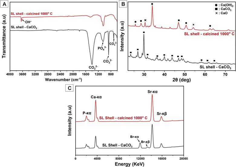 | ||
| Fig. 2 Characteristics of the sand lobster shell powder before and after calcination treatment (A) Fourier transform infrared, (B) X-ray diffraction, and (C) X-ray fluorescence. | ||
The SL shells‘ XRD pattern (Fig. 2(B)) confirms the FTIR results. The carbonate ions were completely broken down during the 1000 °C calcination, fulfilling the chemical process described in eqn (1). The XRD indicated that the peak of the CaCO3 phase appeared dominantly before the calcination process (calcination at 0 °C) based on JCPDS 047-1743.34,35 Meanwhile, the JCPDS 044-1481 confirmed that the dominant diffraction peak formed during the calcination at 1000 °C was Ca(OH)2 with minor CaO peaks in the diffraction planes of (111) and (220) at 31.54° and 54.26°, respectively, based on JCPDS 037-1497.35,36 The Ca(OH)2 peak was dominant because the reaction in eqn (2) happened before the CaO was dissolved in distilled water. After calcination, the SL shells become more hygroscopic, which facilitates the samples' ability to absorb water from the air.36 The crystallite size indicates the crystallinity degree of each sample, which is inversely proportional to the microstrain. The SL shell had similar crystallite sizes before and after calcination at 1000 °C, which were 14.347 ± 6.107 nm and 13.752 ± 4.695 nm, respectively. There was no significant change in the level of crystallinity because only the phase had changed. The lattice parameters of uncalcined SL shells were a = 4.942 Å and c = 16.946 Å, corresponding to the lattice parameter of CaCO3, while the lattice parameters of SL shells after calcination at 1000 °C changed to a = 3.591 Å and c = 4.957 Å, corresponding to Ca(OH)2.35 The lattice parameter change emphasizes that the phase changed because of the calcination treatment. These results are shown in Table 2.
| Samples | Lattice parameter (Å) | Ratio of c/a | Crystallite size (nm) | Microstrain | |
|---|---|---|---|---|---|
| a | c | ||||
| SL shells – CaCO3 | 4.942 | 16.946 | 3.429 | 14.347 ± 6.107 | 0.058 ± 0.050 |
| SL shells – 1000 °C | 3.591 | 4.957 | 1.380 | 13.752 ± 4.695 | 0.062 ± 0.029 |
| HAp | 9.411 | 6.833 | 0.726 | 31.620 ± 4.140 | 0.021 ± 0.013 |
According to the percentage of Ca in the XRF graphic in Fig. 2(C), 1000 °C was the optimum calcination temperature to increase the calcium content. Before calcination, the SL shell has a calcium content percentage of 89.31%, which increases to 93.00% after the calcination process at 1000 °C. The percentage of phosphate element tends to be constant and confirms the FTIR spectra at a wavenumber of 1047.86 cm−1 that does not change after calcination. Interestingly, the high-temperature treatment reduced the total amount of inorganic trace elements from 5.61% to 2.99%. The percentage of calcium element in the calcined SL shell can be used as a calcium source to synthesize HAp powder.
3.2. Hydroxyapatite (HAp) powder
The FTIR was used to describe and determine the functional groups of HAp produced from SL shells in the wavenumber range 4000–400 cm−1. The FTIR spectrum results shown in Fig. 3(A) reveal that the PO43− bending mode, symmetric stretching mode, and asymmetric stretching mode correspond to 554.08, 604.13, and a sharp peak at 1054.54 cm−1, respectively.18,32 The small peak at 1420.65 and 875.43 cm−1 illustrated the carbonate ion (CO32−) stretching vibration,32,33 while the functional group of the OH− stretching mode broadly appeared at a wavenumber of 3576.58, 3434.35 and 1629.41 cm−1, corresponding to the water absorption.37 The OH− functional group in HAp allows water and mineral absorption when the HAp is incorporated into the nanofiber scaffold.38,39 It is beneficial because the cells need water and mineral absorption in the nanofiber for proliferation, and it can also enhance the bioactivity of the nanofiber with HAp filler.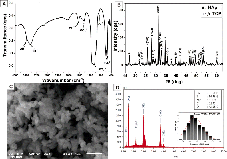 | ||
| Fig. 3 Characteristics of HAp based on (A) FTIR, (B) XRD, (C) SEM and (D) EDX analysis and diameter of HAp particles. | ||
The standard diffraction pattern from JCPDS 09-0432 confirmed the HAp typical diffraction planes of (211), (112), and (300) at angles of 31.18°, 31.72°, and 32.85°, respectively, in addition to other diffraction planes observed in Fig. 3(B).40,41 In addition to HAp, the β-tricalcium phosphate (β-TCP) results demonstrated an insignificant peak. β-TCP can potentially enhance bone tissue growth because it is a calcium phosphate and highly biocompatible with native bone tissues.42,43 Table 2 shows the crystal structure analysis of HAp. The HAp crystallite size formed was 31.620 ± 4.140 nm with lattice parameters at a = 9.411 Å and c = 6.833 Å. These findings confirmed that the predominant crystal phase formed was HAp and identical to the HAp hexagonal structure.14 The crystal defects are expressed in microstrain. The microstrain of HAp is 0.021 ± 0.013, which is good because a small microstrain means the HAp has good crystallinity for bone regeneration application. The high crystallinity of HAp will support the mechanical properties of the nanofiber scaffold.
Fig. 3(C) illustrates the uniform and homogenous morphology of the HAp powder, with relatively small agglomerations resulting from the high-temperature treatment. Using ImageJ software, the size of the HAp particle can be determined. In this study, the HAp size was 0.3577 ± 0.0085 μm. Fig. 3(D) shows the EDX evaluation, indicating a Ca and P mass of 31.51% and 14.58%, respectively, so the Ca/P molar ratio of synthesized HAp was 1.67. This result is appropriate with Ca/P in HAp human bone, which is 1.67,10 and it confirms that the chemical reaction to synthesize Hap, as in eqn (3), was successfully achieved. The small trace element of Mg can be neglected because it may come from the biogenic precursors. However, Mg is one of the inorganic minerals found in trace amounts in natural bone,2,14 which is good for bone regeneration.
3.3. Characterisation of the nanofiber membrane scaffold
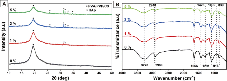
Synthesized nanofibers were characterized to identify their physicochemical properties using XRD, FTIR, and SEM. The XRD results are shown in Fig. 4(A). The peak at 19.36° corresponds to PVA/PVP/CS.24,27,44 The PVA/PVP/CS peak indicated a decrease in crystallinity at a higher concentration of HAp. The presence of HAp on the nanofiber could disrupt the macromolecular chains of the polymer, leading to a decrease in the amount of crystalline polymer. In addition, the interaction between the HAp and the polymer at their interface can also cause the formation of an amorphous polymeric layer.14 The peak showed characteristics of HAp crystals at 25.92, 31.81, 32.92, and 34.68°,40,41 which became sharper proportional to the concentration of HAp. These confirm the presence of HAp in the nanofiber membrane. HAp crystals were expected to enhance the biocompatibility, bioactivity, and osteoconductivity of the nanofiber to stimulate the cell osteoblast for bone growth.The FTIR results of the nanofiber PVA/PVP/CS/HAp are shown in Fig. 4(B). The broad peak at 3270 cm−1 is attributed to the hydrogen bonding OH− group and overlaps with the stretching vibration of N–H.37 A shift in the absorption peak occurred at a higher concentration of HAp towards a wave number of 3338 cm−1. These results show that the hydrogen bonding became stronger due to HAp.27 The peaks at 2940 and 2909 cm−1 are related to the C–H symmetric and antisymmetric stretching vibrations, respectively.24,27,45 The peak at 1656 cm−1 indicates the C![[double bond, length as m-dash]](https://www.rsc.org/images/entities/char_e001.gif) O stretching vibration of amide-type I from CS.24 The CH–OH bending was shown at a wave number of 1423 cm−1.45 The small peaks at 1291 and 916 cm−1 correspond to the C–N stretching of the pyrrolidone ring in PVP,37 while the sharp peak at 1092 and a small peak at 840 cm−1 show C–O stretching vibration, supporting the PVA configuration and C–C bonds,27,45 respectively.
O stretching vibration of amide-type I from CS.24 The CH–OH bending was shown at a wave number of 1423 cm−1.45 The small peaks at 1291 and 916 cm−1 correspond to the C–N stretching of the pyrrolidone ring in PVP,37 while the sharp peak at 1092 and a small peak at 840 cm−1 show C–O stretching vibration, supporting the PVA configuration and C–C bonds,27,45 respectively.
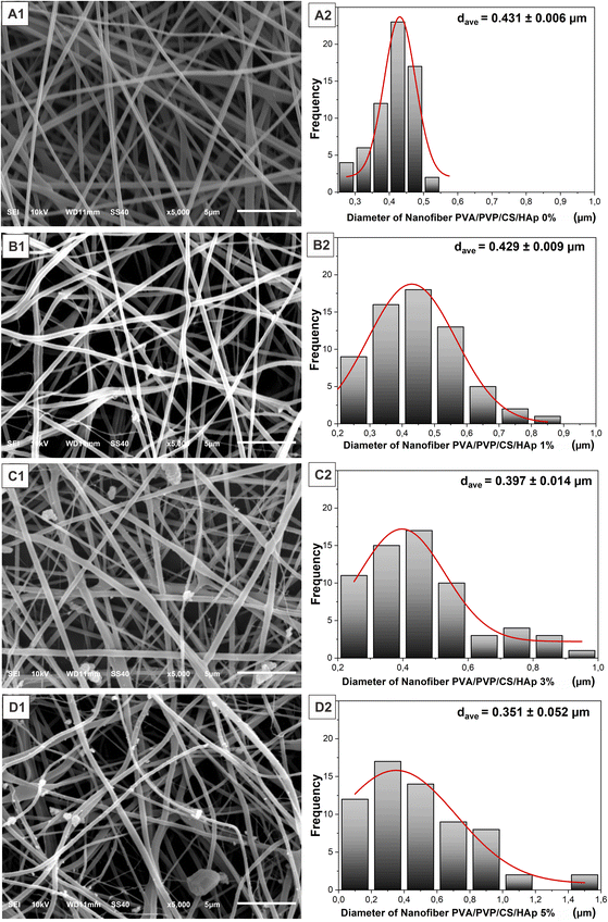
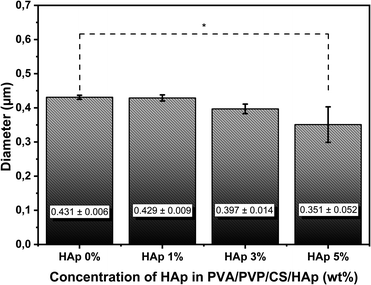
The synthesized HAp was then incorporated into the PVA/PVP/CS nanofiber membrane as a filler to mimic the structure of ECM in the native bone at the nanoscale level. Nanofiber membrane without adding HAp was seen as relatively smooth, well-distributed, and bead-free (Fig. 5(A1 and A2)). In contrast, the morphology of the nanofiber membrane PVA/PVP/CS/HAp at a higher concentration of HAp shows that the agglomeration occurred in the nanofiber with the HAp concentration of 1% to 5% (Fig. 5(B1–D1)). The agglomeration can be neglected because they are still in the submicron scale.27 HAp particles are successfully incorporated and well dispersed in the fiber, which leads to a lower diameter-size nanofiber but a larger-size distribution of the nanofiber, as shown in Fig. 5(B2–D2). The HAp at a concentration of 5% can be incorporated into the fiber with a diameter of 0.351 ± 0.052 μm (Fig. 5(D2)), which decreases compared to lower HAp concentrations of 0, 1, and 3% at 0.431 ± 0.006 μm, 0.429 ± 0.009 μm, and 0.397 ± 0.014 μm, respectively. These results are within the fiber diameter range that mimics the ECM native bone about 100–450 nm.46 The size of nanofibers is inversely proportional to the HAp concentration; the nanofiber size becomes smaller at higher concentrations of HAp. The addition of HAp can lead to higher solution conductivity due to HAp being more conducting than polymer solution.47,48 Hence, the electrical force generated by the electrical field between the needle tip and collector becomes stronger.48 It is beneficial because the smaller nanofiber diameter will provide a larger pore size on the nanofiber surface. The pores on the nanofiber surface are very important to enable the delivery process of water and nutrients to cells,49 and the results of the water absorption ability will be obtained from the swelling test. The presence of HAp in the fiber was also expected to enhance bioactivity properties in the polymer fiber because one of the drawbacks of polymeric scaffolds for biomedical applications is the lack of bioactivity properties.6 Therefore, based on the physicochemical analysis, PVA/PVP/CS/HAp 5% has the potential to mimic ECM structure in native bone.
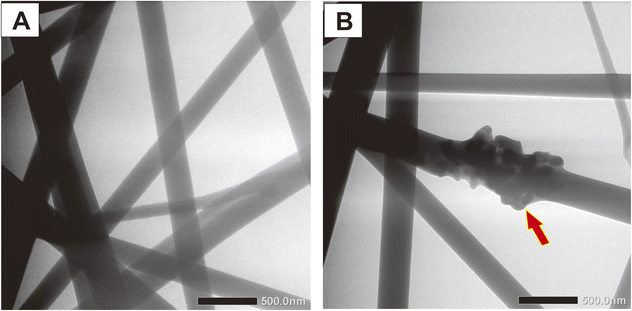
HAp incorporation into the PVA/PVP/CS nanofiber can be seen more clearly through the TEM image in Fig. 7. The red arrow shows that the HAp particle was successfully attached to the nanofiber. Conversely, the nanofiber without additional HAp was seen as smooth. The morphology of the nanofiber observed by TEM analysis emphasizes the SEM image. The presence of HAp in the nanofiber will provide good bioactivity properties to the nanofiber because nanofiber from polymer lacks bioactivity.20 Meanwhile, the HAp as a calcium phosphate has good bioactivity for bone tissues.19,20,50 Bioactivity is a requirement for a material to be used in biomedical applications, especially in bone regeneration. The bioactivity will indicate the material's ability to maintain and even form apatite when interacting with the environment in the body.51 Additionally, the good bioactivity from HAp particles will enhance the cell's ability to attach and proliferate in the nanofiber. In this study, the in vitro test, such as biomineralization on SBF solution and cell viability assay, will be carried out to analyze the nanofiber's bioactivity further based on the additional HAp.
3.4. Mechanical properties of the nanofiber
The tensile strength test was carried out to determine the mechanical properties of the nanofiber. This characteristic is important to analyze because the material used should resemble the mechanical performance of natural human bone in the ECM. The stress and strain graph in Fig. 8(A) can elaborate on the mechanical properties of the nanofiber samples based on differences in HAp concentration. Based on this curve, the elongation break, tensile strength, and Young's modulus of the nanofiber sample can be analyzed. These results are shown in Fig. 8(B–D), as well as in Table 3.| Sample nanofiber | Mechanical properties | ||
|---|---|---|---|
| Elongation break (%) | Tensile strength (MPa) | Young's modulus (MPa) | |
| PVA/PVP/CS/HAp 0% | 42.20 ± 13.19 | 1.99 ± 0.41 | 15.09 ± 7.19 |
| PVA/PVP/CS/HAp 1% | 27.62 ± 5.10 | 2.63 ± 0.23 | 22.68 ± 6.20 |
| PVA/PVP/CS/HAp 3% | 18.11 ± 9.29 | 3.38 ± 1.01 | 25.60 ± 10.21 |
| PVA/PVP/CS/HAp 5% | 23.39 ± 7.36 | 4.34 ± 0.67 | 44.89 ± 7.73 |
Young's modulus is the gradient or slope in the linear region of the stress and strain curve. The higher Young's modulus indicates that the samples are more ductile. In other words, the mechanical properties are more inelastic. Conversely, the smaller Young's modulus, the more elastic the material's properties will be. Based on the Young's modulus of the samples in Fig. 8(D), it can be interpreted that the addition of a higher concentration of HAp particles makes the nanofiber properties more inelastic compared to the nanofiber PVA/PVP/CS with a lower concentration of HAp. The nanofiber with HAp 5% has the highest level of Young's modulus of 44.89 ± 7.73 MPa. The result also indicates an increase in Young's modulus for nanofiber HAp 3 and 1% at 25.60 ± 10.21 and 22.68 ± 6.20 MPa, respectively, compared to that of the nanofiber without HAp, 15.09 ± 7.19 MPa. This is because the mechanical properties of HAp particles that fill the fiber membrane are rigid, making the nanofiber have ductile properties. The tensile strengths of the samples are shown in Fig. 8(C). Based on Fig. 8(C), the higher the concentration of HAp, the higher the tensile strength will become.
The combination of the HAp's rigidity and the polymer's elasticity causes higher tensile strength for the higher HAp concentration. The decrease in fiber diameter may also enhance the mechanical properties.52 On the other side, the elongation break was analyzed to evaluate the brittleness of nanofiber samples. In general, the more HAp incorporated into the nanofiber, the lower the elongation break, which means the higher the brittleness of the nanofiber. However, the PVA/PVP/CS/HAp 5% has a higher elongation break than 3%. It showed that HAp 5% has excellent mechanical properties, as shown in Fig. 8(B and C), and most closely approximates the mechanical properties of trabecula bone, which has a tensile strength of 5–10 MPa and Young's modulus of 50–100 MPa.57 These results confirm that the incorporation of HAp into the nanofiber could reinforce mechanical properties due to the interfacial hydrogen bonding between HAp and polymer.38,39 Moreover, the HAp is an anisotropic filler in the nanofiber, which is a desirable filler to improve the mechanical properties and uniaxial stretching strength in terms of stress distribution.53,54 The incorporation of HAp into the nanofiber acts as stress dissipation, resulting in delayed network rupturing, leading to the nanofiber's less fatigue behavior.53
3.5. Swelling ratio, degradability, and protein adsorption
The protein adsorption of the nanofiber substrate could influence the biological properties and improve the cellular response.55 In this study, protein adsorption was investigated to determine the effect of HAp incorporation into nanofiber scaffold membranes. Fig. 9(A) depicts the amount of protein adsorbed onto the nanofiber, and the addition of HAp significantly increases protein adsorption. As discussed by Januariyasa et al.,27 the HAp incorporation as a calcium phosphate ceramic into the nanofiber seems to add favorable binding sites for proteins due to the electrostatic interaction of Ca2+ and PO43− ions with charged sites on the proteins so that the HAp particle may provide a larger surface area for protein binding. Furthermore, as reported by Ghobani et al.,56 the water absorption expressed in the swelling ratio may also play a role in increasing protein adsorption. HAp enhances the hydrophilicity of the nanofiber due to the OH− functional groups contained in HAp, and it will increase water absorption. The details of water absorption are discussed in the swelling test analysis.The swelling test was performed to analyze the physical adsorption properties and structural stability of the nanofiber scaffold membrane in an aqueous environment58,64 based on various concentrations of HAp through immersion in distilled water for 24 h at room temperature. The result of the swelling test was obtained using eqn (4) and shown in Fig. 9(B). Based on the test results, PVA/PVP/CS nanofiber without additional HAp has the lowest swelling ratio at 102.45 ± 6.19%. In general, the swelling ratio increases when the HAp concentration increases due to HAp containing a hydrogen functional group (OH−), as shown in the FTIR test results in Fig. 3(A). The OH− functional group in HAp imparts hydrophilic properties.38,39 It retains more water when incorporated into the PVA/PVP/CS nanofiber. In addition, based on the results of the nanofiber diameter analysis in Fig. 6, the increasing HAp concentration leads to a smaller nanofiber diameter so that the nanofiber surface will have a larger pore size. The larger pore size on the nanofiber surface will increase the amount of water absorbed.49
However, at the same time, 5% HAp concentration caused slight agglomeration on the nanofiber surface, leading to a decrease in the scaffold's porosity and reducing the physical absorption capacity of water because the water amount that could penetrate into the pores was reduced;58 this result was also reported by Januariyasa et al.27 Furthermore, the HAp may provide physical crosslinking inside the nanofiber, leading to the enhanced nanofiber's hydrophobicity.59 Nevertheless, HAp is a hydrophilic filler, and the effect of HAp as a hydrophilic filler was more significant than HAp itself as a cross-linker (causing the hydrophobicity),60,61 which is the reason the effect of hydrophobicity in water absorption just emerged in the nanofiber with 5% of HAp, so the swelling ratio value of nanofiber PVA/PVP/CS/HAp 5% decreased from 162.85 ± 16.26% compared to the HAp concentration of 3% at 174.88 ± 6.18%, contrary, the swelling ratio increase from HAp 0 to 3%. These results show that the PVA/PVP/CS/HAp nanofiber could swell water as expected and has the potential to let the body fluid, minerals, and cells penetrate the porous scaffold so that it is possible to enhance new bone regeneration.
The degradability is related to swelling due to water absorption, as reported by Patriati et al.;30 the swelling process happened simultaneously with the degradation process, and the swelling process led to the degradation process.62 The incorporation of HAp into the nanofiber offers hydrophilic water absorption because of the OH− functional group in HAp,27 as previously described. When the PBS solution interacts with nanofiber membranes, the HAp in the nanofiber surface will increase the water absorption in the PBS solution, and the water diffusion will lead to hydrolytic cleavage of the polymeric chain and falls off into the PBS supernatant.30,63 The solved polymeric chain in the PBS solution will be counted as percent degradation at a particular time. Fig. 9(C) demonstrates the percent degradation of the nanofiber at 1, 6, 12, and 24 h. All samples sharply increased at the first hour, but the nanofiber with 5% of HAp went slower from 12 to 24 h than the nanofiber with 3% of HAp, and this happened because the amount of water absorption of HAp 5% was smaller than 3%, as shown in Fig. 9(B), so the increasing degradation of the nanofiber with 3% of HAp was the fastest among the others. Overall, the prepared nanofiber has good degradability for bone tissue engineering.
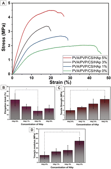 | ||
| Fig. 8 (A) The stress and strain curve and mechanical property analysis of nanofiber PVA/PVP/CS/HAp: (B) elongation break, (C) tensile strength, and (D) Young's modulus. | ||
 | ||
| Fig. 9 (A) Protein adsorption (B) swelling ratio and (C) biodegradability analysis of PVA/PVP/CS nanofiber with various concentrations of HAp. | ||
3.6. Biactivity nanofiber
Bioactivity is the ability of the material to attach, interact, and form the bone-bonding interface between the scaffold and the surrounding environment of native bone tissues so it can support the cell differentiation process.31,51 This property is one of the requirements that biomaterials must have. In this study, we prepared the SBF solution, as in previous research,31 with a mineral composition that resembles the fluid in the human body. The nanofiber membrane was immersed in SBF solution for 1, 3, and 5 days in an incubator. After the immersion, the samples were rinsed with distilled water and characterized using SEM-EDX and FTIR to observe and analyze the mineralized apatite formation.Based on the SEM image results in Fig. 10, it can be seen that in the nanofiber, without the addition of HAp, no mineralized apatite was formed. In contrast, in the nanofiber, with the addition of HAp, the apatite begins to form. The higher concentration of HAp in the nanofiber can promote more apatite formation and indicates that the nanofiber has good bioactivity properties with higher levels of HAp. The growth of mineralized apatite in each group of nanofiber scaffolds increased with the length of incubation time, and it reached the peak at nanofiber PVA/PVP/CS/HAp 5% after 5 days of incubation as shown in the red arrow of the SEM images in Fig. 11. The bioactivity properties of the material are needed to support cells in differentiation and support the material in attaching and interacting with surrounding tissues.21
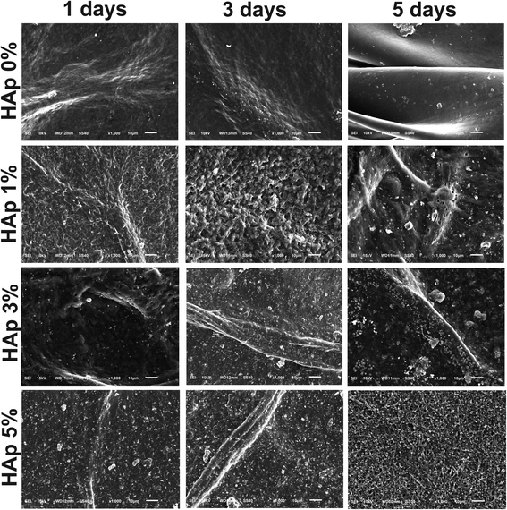 | ||
| Fig. 10 The effect of HAp on the nanofiber PVA/PVP/CS bioactivity immersed for 1, 3, and 5 days in SBF solution. | ||
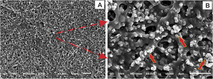 | ||
| Fig. 11 SEM image of nanofiber scaffold PVA/PVP/CS/HAp 5% after immersion in SBF solution for 5 days with (A) low magnification and (B) high magnification. | ||
The FTIR results are shown in Fig. 12 to analyze the time duration effect of immersion of the PVA/PVP/CS/HAp 5% in SBF solution. The PVA/PVP/CS/HAp 5%, after the 1, 3, and 5 days of immersion, was tested to confirm the formed apatite. It can be seen that the phosphate functional group (PO43−) appeared clearly in nanofiber PVA/PVP/CS/HAp 5% after 3 and 5 days immersion at wavenumbers 1144 dan 1034 cm−1 (ref. 18 and 32) and carbonate functional (CO32−) group at 1416 cm−1 (ref. 32 and 33) but not too clear in PVA/PVP/CS/HAp 5% after 1 day immersion. The longer the immersion in the SBF solution, the clearer the phosphate and carbonate groups formed. The functional group in Fig. 12 is a characteristic of mineralized apatite, and it justifies that the apatite was successfully formed at longer immersion times in SBF solutions. This result indicates that the nanofiber in the same level of HAp concentration has bioactivity to mineralize the apatite during immersion in SBF. In other words, PVA/PVP/CS/HAp 5% is bioactive and meets the requirements as a biomaterial for bone tissue engineering applications. The results of the morphological structure analysis through SEM are shown in Fig. 10 and 11.
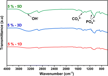 | ||
| Fig. 12 FTIR analysis of nanofiber PVA/PVP/CS/HAp 5% after soaking for 1, 3, and 5 days in SBF solution. | ||
Based on the results of EDX analysis in Fig. 13, it was interesting to find an increase in calcium content based on the duration of immersion in SBF solution. The Ca/P values for PVA/PVP/CS/HAp 5% nanofibers after soaking in SBF solution were 1.20, 1.33, and 1.38, respectively. This Ca/P value is still below the Ca/P value in apatite, namely Ca/P < 1.67, due to the presence of several trace elements.65 Trace elements such as Na+ and Mg2+ are also found in native human bones.65,66 The apatite formed increases with increasing HAp concentration in the nanofiber. HAp has a composition that resembles the minerals in bones. Therefore, HAp incorporated into the nanofiber will have bioactive properties, allowing nanofibers to mineralize apatite when interacting with body fluids.19,27,31,50
 | ||
| Fig. 13 EDX spectra of apatite from nanofiber PVA/PVP/CS/HAp 5% after immersion for (A) 1, (B) 3, and (C) 5 days in SBF solution. | ||
3.7. Antibacterial activity
Antibacterial activity of the nanofiber was performed against P. aeruginosa as a Gram-negative and S. aureus as a Gram-positive bacterium. This study aims to determine the antibacterial effect of dissolved CS on a nanofiber in the PVP. As we mentioned in the introduction, the CS is expected to carry antibacterial properties. Generally, adding PVP/CS into the PVA polymeric solution enhances the nanofiber's antibacterial activity insignificantly. Fig. 14(A) illustrates that the ZOI diameter of PVA/PVP/CS/HAp 0% on both bacteria was larger than the control (pure nanofiber PVA). It indicates that the introduced PVP/CS in PVA affects the antibacterial properties. However, the analysis of these parameters was beyond the scope of this research. On the other side, the HAp does not generate antibacterial activity, and the ZOI diameter was not changed relatively in nanofiber PVA/PVP/CS/HAp 5% compared to HAp 0%, and this study was in line with Lamkhao et al.,67 which showed the HAp has no antibacterial activity. These results can be seen qualitatively in Fig. 14(B).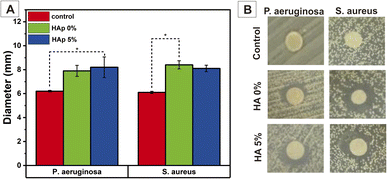 | ||
| Fig. 14 Antibacterial activity against P. aeruginosa and S. aureus based on diameter zone of inhibition (A) semi-quantitative and (B) qualitative. | ||
3.8. Cell viability
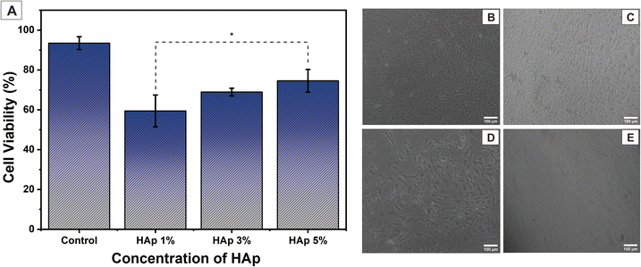
The cytotoxicity of nanofiber samples against cell osteoblast (MC3T3E1) was determined using an MTT assay through the color changes in the MTT reagent, which showed cell metabolic activity. Briefly, the cell MC3T3E1 cultured on nanofiber scaffold samples was then treated with MTT reagent and incubated for 24 h. Then, there will be a color change in the MTT reagent from yellow (tetrazolium), which will be reduced and changed to purple (formazan dye), which is caused by the metabolic activity of living cells.68 This color change was observed via a spectrophotometer at a wavenumber of 570 nm. The cell viability of the percentage value was calculated using eqn (5). The test was carried out three times in each group sample. The results can be interpreted as cytotoxicity samples to the cells.In this test, nanofiber PVA/PVP/CS/HAp samples with HAp concentrations of 1, 3, and 5% were used to determine the effect of HAp on MC3T3E1 cell viability. Based on the test results, it was found that after incubation for 24 h, nanofiber PVA/PVP/CS/HAp 5% had the highest percentage of cell viability at 73.56 ± 5.72%, a decrease from the control at 92.45 ± 3.21%. These results show that cells can still proliferate in nanofiber samples with higher HAp concentrations. The synthesized HAp is a material that resembles the inorganic minerals in native human bone, so it has biocompatible properties with bone cells. It will allow osteoblast cells MC3T3E1 to proliferate and differentiate so that higher HAp concentrations will support better proliferation of osteoblast cells and will have a higher performance of cell viability than nanofibers with lower HAp concentrations.68 The decrease in the percentage of cell viability occurred in PVA/PVP/CS/HAp 3 and 1% at 68.93 ± 1.93% and 59.44 ± 7.98%, respectively. This percentage value is not enough to make the cell proliferate properly. Therefore, HAp 5% is the optimal concentration in PVA/PVP/CS nanofibers for biocompatibility with bone tissue formation.
The morphology of cells cultured on PVA/PVP/CS/HAp nanofibers is shown in Fig. 15. The image shows cells attached to the surface of the scaffold. Fig. 15(B) shows the control, i.e., cell treatment without a scaffold. Fig. 15(C) shows the nanofiber with HAp 5%, and Fig. 15(D) and (E) are nanofibers with a concentration of HAp 3 and 1%, respectively. In nanofibers with a HAp concentration of 3%, cells display a decrease in cell viability. In comparison, in nanofibers with a HAp concentration of 1%, the number of cells was getting smaller and showed a decrease in cell proliferation. This cell morphology image confirms the percentage of cell viability in Fig. 15(A). Moreover, the increasing addition of HAp into the nanofiber reveals better cell viability due to the bioactivity and biocompatibility of HAp for osteoblast cells to attach to the scaffold surface.69 Overall, nanofiber PVA/PVP/CS/HAp 5% is ideal for cells to attach and proliferate.
3.9. Cell differentiation
The ideal scaffold nanofiber should also promote osteogenic activity. It is important because the promotion of osteogenic differentiation will lead to successful bone regeneration.70,71 The ALP activity is a specific enzyme secreted by active osteoblasts that will confirm the early osteogenic differentiation marker in MC3T3E1 cells.61,72 After being incubated for 7 days, the quantitative ALP analysis is shown in Fig. 16(A), and the qualitative ALP activity is presented in Fig. 16(B–F). Interestingly, after 7 days of incubation, the ALP in MC3T3E1 cultured in nanofiber PVA/PVP/CS/HAp was significantly increased compared to the control (without nanofiber). This increase is in line with the incorporation of HAp into the nanofiber, and it emphasizes that the presence of HAp in the nanofiber scaffold promotes osteogenic differentiation, thus facilitating bone tissue regeneration. ALP staining images observed the ALP activity qualitatively in Fig. 16(B–F). Overall, the prepared nanofiber scaffold PVA/PVP/CS/HAp revealed promising capabilities for osteogenic differentiation.4. Conclusion
The HAp with a hexagonal structure derived from SL shells (Panulirus homarus) was successfully synthesized using precipitation methods, and the molar ratio of Ca/P was 1.67. The XRD results showed that β-TCP was also formed, which is one of the calcium phosphates with high biocompatibility for human bones. HAp was also successfully incorporated and well dispersed into the PVA/PVP/CS nanofiber membrane using the electrospinning method with small agglomerations. Despite not being significant, the CS provides antibacterial properties, but the HAp does not generate antibacterial activity. Based on the mechanical testing, the higher concentration of HAp in the nanofiber improves the tensile strength and Young's modulus properties of the nanofiber for bone tissue engineering applications. The addition of HAp with concentrations of 1, 3, and 5% into the nanofiber mimics the ECM structure of native bone at the nanoscale level and also enhances the bioactivity properties of the nanofiber. Adding HAp will enhance the apatite mineralization bioactivity based on time immersion in the SBF solution. Additionally, the nanofiber with various HAp concentrations enhances the water absorption ability to deliver the mineral to the cell; the water absorption ability affects the improvement of the degradation process and protein adsorption of the nanofiber, and these results play an important role in biomedical applications. According to the cell viability assay incubated for 24 h, the nanofiber PVA/PVP/CS/HAp 5% can support the MC3T3E1 cell to attach and proliferate. The higher HAp concentration can also significantly promote the osteogenic differentiation of MC3T3E1 cells based on the ALP activity for 7 days of incubation. Hence, HAp derived from SL shells with a 5% concentration of HAp in the nanofiber PVA/PVP/CS has good biocompatibility in the in vitro test and is the most potential scaffold for bone tissue engineering applications.Author contributions
I. Kadek Hariscadra Dinatha: conceptualization, designed the experiments, performed the experiments and collected data, validation, writing and original draft preparation. Arian Hermawan Diputra: designed the experiments, performed the experiments, and review. Hevi Wihadmadyatami: investigation, review, and editing. Juliasih Partini: conceptualization, validation, and supervision. Yusril Yusuf: conceptualization, validation, supervision, review and editing, funding acquisition, and project administration.Conflicts of interest
The authors declare that they have no known competing financial interests or personal relationships that could influence the work in this article.Acknowledgements
This research was supported by the Masters to Doctoral Education Scholarship Programme for Excellent Scholars (PMDSU Batch VI: 2198/UN1/DITLIT/DitLit/PT.01.03/2023); and Enhancing International Publication (PKPI: 165.15/E4.4/KU/2023) from the Ministry of Education, Culture, Research and Technology, Republic of Indonesia. The authors thank the Material Physics Laboratory and Integrated Laboratory for Research and Testing Universitas Gadjah Mada for permission to use the facilities and technical assistance. We also thank the Research Center of Marine and Land Bioindustry of the National Research and Innovation Agency for providing the SL shells as the raw material and the Shanghai Institute of Ceramics, Chinese Academy of Science, for helpful discussion.References
- H. A. Permatasari and Y. Yusuf, Characteristics of Carbonated Hydroxyapatite Based on Abalone Mussel Shells (Halioitis asinina) Synthesized by Precipitation Method with Aging Time Variations, IOP Conf. Ser.: Mater. Sci. Eng., 2019, 546(4), 042031 CrossRef CAS.
- H. Qu, H. Fu, Z. Han and Y. Sun, Biomaterials for bone tissue engineering scaffolds: a review, RSC Adv., 2019, 9(45), 26252–26262 RSC.
- M. M. Stevens, Biomaterials for bone tissue engineering, Mater. Today, 2008, 11(5), 18–25 CrossRef CAS.
- T. Li, et al., 3D Printing of Hot Dog-Like Biomaterials with Hierarchical Architecture and Distinct Bioactivity, Adv. Sci., 2019, 6(19), 1901146 CrossRef CAS PubMed.
- M. Akram, R. Ahmed, I. Shakir, W. A. W. Ibrahim and R. Hussain, Extracting hydroxyapatite and its precursors from natural resources, J. Mater. Sci., 2014, 49(4), 1461–1475 CrossRef CAS.
- R. Yunus Basha, S. T. S. Kumar and M. Doble, Design of biocomposite materials for bone tissue regeneration, Mater. Sci. Eng., C, 2015, 57, 452–463 CrossRef CAS PubMed.
- H. D. Barth, E. A. Zimmermann, E. Schaible, S. Y. Tang, T. Alliston and R. O. Ritchie, Characterization of the effects of X-ray irradiation on the hierarchical structure and mechanical properties of human cortical bone, Biomaterials, 2011, 32(34), 8892–8904 CrossRef CAS PubMed.
- T. Gong, J. Xie, J. Liao, T. Zhang, S. Lin and Y. Lin, Nanomaterials and bone regeneration, Bone Res., 2015, 3(1), 15029 CrossRef CAS PubMed.
- V. J. Mawuntu and Y. Yusuf, Porous-structure engineering of hydroxyapatite-based scaffold synthesized from Pomacea canaliculata shell by using polyethylene oxide as polymeric porogen, IOP Conf. Ser.: Mater. Sci. Eng., 2018, 432, 012045 Search PubMed.
- S. V. Dorozhkin, Calcium orthophosphate bioceramics, Ceram. Int., 2015, 41(10), 13913–13966 CrossRef CAS.
- S. Lala, S. Brahmachari, P. K. Das, D. Das, T. Kar and S. K. Pradhan, Biocompatible nanocrystalline natural bonelike carbonated hydroxyapatite synthesized by mechanical alloying in a record minimum time, Mater. Sci. Eng., C, 2014, 42, 647–656 CrossRef CAS PubMed.
- A. Aminatun, T. Suciati, Y. W. Sari, M. Sari, K. A. Alamsyah, W. Purnamasari and Y. Yusuf, Biopolymer-based polycaprolactone-hydroxyapatite scaffolds for bone tissue engineering, Int. J. Polym. Mater. Polym. Biomater., 2021, 72(5), 376–385 CrossRef.
- A. M. M. Amin and E. M. M. Ewais, Bioceramic Scaffolds, in Scaffolds in Tissue Engineering – Materials, Technologies and Clinical Applications, ed. F. Baino, InTech, 2017, DOI:10.5772/intechopen.70194.
- G. Ma and X. Y. Liu, Hydroxyapatite: Hexagonal or Monoclinic?, Cryst. Growth Des., 2009, 9(7), 2991–2994 CrossRef CAS.
- R. Rial, M. González-Durruthy, Z. Liu and J. M. Ruso, Advanced Materials Based on Nanosized Hydroxyapatite, Molecules, 2021, 26(11), 3190 CrossRef CAS PubMed.
- V. Lalzawmliana, et al., Marine organisms as a source of natural matrix for bone tissue engineering, Ceram. Int., 2019, 45(2), 1469–1481 CrossRef CAS.
- C. E. Davies, et al., A comparison of the structure of American (Homarus americanus) and European (Homarus gammarus) lobster cuticle with particular reference to shell disease susceptibility, J. Invertebr. Pathol., 2014, 117, 33–41 CrossRef PubMed.
- I. Kadek Hariscandra Dinatha, M. A. Jamilludin, A. I. Supii, H. Wihadmadyatami, J. Partini and Y. Yusuf, Porous scaffold hydroxyapatite from sand lobster shells (Panulirus homarus) using polyethylene oxide/chitosan as polymeric porogen for bone tissue engineering, J. Biomed. Mater. Res., Part B, 2024, 112(1), e35341 CrossRef CAS PubMed.
- A. A. Ashraf, S. M. Zebarjad and M. J. Hadianfard, The cross-linked polyvinyl alcohol/hydroxyapatite nanocomposite foam, J. Mater. Res. Technol., 2019, 8(3), 3149–3157 CrossRef CAS.
- C. D. Nascimento, J. P. M. Issa, R. R. D. Oliveira, M. M. Iyomasa, S. Siéssere and S. C. H. Regalo, Biomaterials Applied to the Bone Healing Process, Int. J. Morphol., 2007, 25(4), 839–846 Search PubMed.
- X. Wang, B. Ding and B. Li, Biomimetic electrospun nanofibrous structures for tissue engineering, Mater. Today, 2013, 16(6), 229–241 CrossRef CAS PubMed.
- M. Tahir, S. Vicini and A. Sionkowska, Electrospun Materials Based on Polymer and Biopolymer Blends—A Review, Polymers, 2023, 15(7), 1654 CrossRef CAS PubMed.
- X. Wang, et al., Electrospun Micropatterned Nanocomposites Incorporated with Cu 2 S Nanoflowers for Skin Tumor Therapy and Wound Healing, ACS Nano, 2017, 11(11), 11337–11349 CrossRef CAS PubMed.
- S. Wu, K. Li, W. Shi and J. Cai, Preparation and performance evaluation of chitosan/polyvinylpyrrolidone/polyvinyl alcohol electrospun nanofiber membrane for heavy metal ions and organic pollutants removal, Int. J. Biol. Macromol., 2022, 210, 76–84 CrossRef CAS PubMed.
- P. Franco and I. De Marco, The Use of Poly(N-vinyl pyrrolidone) in the Delivery of Drugs: A Review, Polymers, 2020, 12(5), 1114 CrossRef CAS PubMed.
- M. Sari, N. Kristianto, C. Chotimah, I. Ana and Y. Yusuf, Carbonated Hydroxyapatite-Based Honeycomb Scaffold Coatings on a Titanium Alloy for Bone Implant Application—Physicochemical and Mechanical Properties Analysis, Coatings, 2021, 11(8), 941 CrossRef CAS.
- I. K. Januariyasa, I. D. Ana and Y. Yusuf, Nanofibrous poly(vinyl alcohol)/chitosan contained carbonated hydroxyapatite nanoparticles scaffold for bone tissue engineering, Mater. Sci. Eng., C, 2020, 107, 110347 CrossRef CAS PubMed.
- R. LogithKumar, A. KeshavNarayan, S. Dhivya, A. Chawla, S. Saravanan and N. Selvamurugan, A review of chitosan and its derivatives in bone tissue engineering, Carbohydr. Polym., 2016, 151, 172–188 CrossRef CAS PubMed.
- D. J. Patty, et al., The enhanced properties and bioactivity of poly-ε-caprolactone/poly lactic- co -glycolic acid doped with carbonate hydroxyapatite–egg white, RSC Adv., 2023, 13(49), 34427–34438 RSC.
- A. Patriati, R. Ardhani, H. D. Pranowo, E. G. R. Putra and I. D. Ana, The Effect of Freeze-Thaw Treatment to the Properties of Gelatin-Carbonated Hydroxypatite Membrane for Nerve Regeneration Scaffold, Key Eng. Mater., 2016, 696, 129–144 Search PubMed.
- T. Kokubo and H. Takadama, How useful is SBF in predicting in vivo bone bioactivity?, Biomaterials, 2006, 27(15), 2907–2915 CrossRef CAS PubMed.
- I. Ezekiel, S. R. Kasim, Y. M. B. Ismail and A.-F. M. Noor, Nanoemulsion synthesis of carbonated hydroxyapatite nanopowders: Effect of variant CO32−/PO43− molar ratios on phase, morphology, and bioactivity, Ceram. Int., 2018, 44(11), 13082–13089 CrossRef CAS.
- H. Nagai, et al., Effects of low crystalline carbonate apatite on proliferation and osteoblastic differentiation of human bone marrow cells, J. Mater. Sci.: Mater. Med., 2015, 26(2), 99 CrossRef PubMed.
- H. Peng, et al., Preparation of hierarchical mesoporous CaCO3 by a facile binary solvent approach as anticancer drug carrier for etoposide, Nanoscale Res. Lett., 2013, 8(1), 321 CrossRef PubMed.
- P. Krongkitsiri, W. Krongkitsiri, S. Phukird and U. Tipparach, A comparison of dielectric properties of eggshells from free-range system and control-range system, Mater. Today: Proc., 2021, 47, 3617–3623 CAS.
- G. Gergely, et al., Nano-hydroxyapatite preparation from biogenic raw materials, Open Chem., 2010, 8(2), 375–381 CAS.
- C. Christou, K. Philippou, T. Krasia-Christoforou and I. Pashalidis, Uranium adsorption by polyvinylpyrrolidone/chitosan blended nanofibers, Carbohydr. Polym., 2019, 219, 298–305 CrossRef CAS PubMed.
- C. Shuai, et al., A graphene oxide-Ag co-dispersing nanosystem: Dual synergistic effects on antibacterial activities and mechanical properties of polymer scaffolds, Chem. Eng. J., 2018, 347, 322–333 CrossRef CAS.
- G.-M. Kim, P. Simon and J.-S. Kim, Electrospun PVA/HAp nanocomposite nanofibers: biomimetics of mineralized hard tissues at a lower level of complexity, Bioinspiration Biomimetics, 2008, 3(4), 046003 CrossRef PubMed.
- M. Sari, P. Hening, C. Chotimah, I. D. Ana and Y. Yusuf, Bioceramic hydroxyapatite-based scaffold with a porous structure using honeycomb as a natural polymeric Porogen for bone tissue engineering, Biomater. Res., 2021, 25(1), 2 CrossRef CAS PubMed.
- D. J. Patty, A. D. Nugraheni, I. D. Ana and Y. Yusuf, In vitro bioactivity of 3D microstructure hydroxyapatite/collagen based-egg white as an antibacterial agent, J. Biomed. Mater. Res., Part B, 2022, 110(6), 1412–1424 CrossRef CAS PubMed.
- V. J. Mawuntu and Y. Yusuf, Porous structure engineering of bioceramic hydroxyapatite-based scaffolds using PVA, PVP, and PEO as polymeric porogens, J. Asian Ceram. Soc., 2019, 7(2), 161–169 CrossRef.
- Y. Rizkayanti and Y. Yusuf, Optimization of the Temperature Synthesis of Hydroxyapatite from Indonesian Crab Shells, Int. J. Nanoelectron. Mater., 2019, 12(1), 85–92 Search PubMed.
- S. Wu, K. Li, W. Shi and J. Cai, Chitosan/polyvinylpyrrolidone/polyvinyl alcohol/carbon nanotubes dual layers nanofibrous membrane constructed by electrospinning-electrospray for water purification, Carbohydr. Polym., 2022, 294, 119756 CrossRef CAS PubMed.
- Y.-T. Jia, J. Gong, X.-H. Gu, H.-Y. Kim, J. Dong and X.-Y. Shen, Fabrication and characterization of poly (vinyl alcohol)/chitosan blend nanofibers produced by electrospinning method, Carbohydr. Polym., 2007, 67(3), 403–409 CrossRef CAS.
- A. Sh. Asran, S. Henning and G. H. Michler, Polyvinyl alcohol–collagen–hydroxyapatite biocomposite nanofibrous scaffold: Mimicking the key features of natural bone at the nanoscale level, Polymer, 2010, 51(4), 868–876 CrossRef CAS.
- B. Chaudhuri, B. Mondal, S. K. Ray and S. C. Sarkar, A novel biocompatible conducting polyvinyl alcohol (PVA)-polyvinylpyrrolidone (PVP)-hydroxyapatite (HAP) composite scaffolds for probable biological application, Colloids Surf., B, 2016, 143, 71–80 CrossRef CAS PubMed.
- D. H. Reneker and A. L. Yarin, Electrospinning jets and polymer nanofibers, Polymer, 2008, 49(10), 2387–2425 CrossRef CAS.
- W.-E. Teo and S. Ramakrishna, Electrospun nanofibers as a platform for multifunctional, hierarchically organized nanocomposite, Compos. Sci. Technol., 2009, 69(11–12), 1804–1817 CrossRef CAS.
- A. Herbanu, I. D. Ana, R. Ardhani and W. Siswomihardjo, Fibrous PVA Matrix Containing Strontium-Substituted Hydroxyapatite Nanoparticles from Golden Apple Snail (Pomacea canaliculata L.) Shells for Bone Tissue Engineering, Bioengineering, 2023, 10(7), 844 CrossRef CAS PubMed.
- P. Feng, et al., Characterizations and interfacial reinforcement mechanisms of multicomponent biopolymer based scaffold, Mater. Sci. Eng., C, 2019, 100, 809–825 CrossRef CAS PubMed.
- S.-C. Wong, A. Baji and S. Leng, Effect of fiber diameter on tensile properties of electrospun poly(ε-caprolactone), Polymer, 2008, 49(21), 4713–4722 CrossRef CAS.
- P. Das, et al., Borophene Based 3D Extrusion Printed Nanocomposite Hydrogel for Antibacterial and Controlled Release Application, Adv. Funct. Mater., 2024, 2314520 CrossRef.
- S. Ganguly and S. Margel, A Review on Synthesis Methods of Phyllosilicate- and Graphene-Filled Composite Hydrogels, J. Compos. Sci., 2022, 6(1), 15 CrossRef CAS.
- H. Liao, et al., Improved cellular response on multiwalled carbon nanotube-incorporated electrospun polyvinyl alcohol/chitosan nanofibrous scaffolds, Colloids Surf., B, 2011, 84(2), 528–535 CrossRef CAS PubMed.
- F. M. Ghorbani, B. Kaffashi, P. Shokrollahi, E. Seyedjafari and A. Ardeshirylajimi, PCL/chitosan/Zn-doped nHA electrospun nanocomposite scaffold promotes adipose derived stem cells adhesion and proliferation, Carbohydr. Polym., 2015, 118, 133–142 CrossRef CAS PubMed.
- M. Yaszemski, Evolution of bone transplantation: molecular, cellular and tissue strategies to engineer human bone, Biomaterials, 1996, 17(2), 175–185 CrossRef CAS PubMed.
- Z. X. Meng, Y. S. Wang, C. Ma, W. Zheng, L. Li and Y. F. Zheng, Electrospinning of PLGA/gelatin randomly-oriented and aligned nanofibers as potential scaffold in tissue engineering, Mater. Sci. Eng., C, 2010, 30(8), 1204–1210 CrossRef CAS.
- A. Ghosh, J. T. Orasugh, S. S. Ray and D. Chattopadhyay, Integration of 3D Printing–Coelectrospinning: Concept Shifting in Biomedical Applications, ACS Omega, 2023, 8(31), 28002–28025 CrossRef CAS PubMed.
- S. Ganguly and N. Ch. Das, Water Uptake Kinetics and Control Release of Agrochemical Fertilizers from Nanoclay-Assisted Semi-interpenetrating Sodium Acrylate-Based Hydrogel, Polym.-Plast. Technol. Eng., 2017, 56(7), 744–761 CrossRef CAS.
- S. Anjum, et al., Multifunctional electrospun nanofibrous scaffold enriched with alendronate and hydroxyapatite for balancing osteogenic and osteoclast activity to promote bone regeneration, Front. Bioeng. Biotechnol., 2023, 11, 1302594 CrossRef PubMed.
- V. Salaris, D. López, J. M. Kenny and L. Peponi, Hydrolytic Degradation and Bioactivity of Electrospun PCL-Mg-NPs Fibrous Mats, Molecules, 2023, 28(3), 1001 CrossRef CAS PubMed.
- K. Zhang, et al., Degradation of electrospun SF/P(LLA-CL) blended nanofibrous scaffolds in vitro, Polym. Degrad. Stab., 2011, 96(12), 2266–2275 CrossRef CAS.
- F. Beladi, S. Saber-Samandari and S. Saber-Samandari, Cellular compatibility of nanocomposite scaffolds based on hydroxyapatite entrapped in cellulose network for bone repair, Mater. Sci. Eng., C, 2017, 75, 385–392 CrossRef CAS PubMed.
- S. V. Dorozhkin and M. Epple, Biologcal and medical significance of calcium phosphate, Angew. Chem., Int. Ed., 2002, 41, 3130–3146 CrossRef CAS PubMed.
- K. Ishikawa, M. L. Munar, K. Tsuru and Y. Miyamoto, Fabrication of carbonate apatite honeycomb and its tissue response, J. Biomed. Mater. Res., Part A, 2019, 107(5), 1014–1020 CrossRef CAS PubMed.
- S. Lamkhao, et al., Synthesis of Hydroxyapatite with Antibacterial Properties Using a Microwave-Assisted Combustion Method, Sci. Rep., 2019, 9(1), 4015 CrossRef PubMed.
- M. Sari, P. Hening, C. Chotimah, I. D. Ana and Y. Yusuf, Porous structure of bioceramics carbonated hydroxyapatite-based honeycomb scaffold for bone tissue engineering, Mater. Today Commun., 2021, 26, 102135 CrossRef CAS.
- N. Shanmugasundaram, P. Ravichandran, P. N. Reddy, N. Ramamurty, S. Pal and K. P. Rao, Collagenchitosan polymeric sca!olds for the in vitro culture of human epidermoid carcinoma cells, Biomaterials, 2001, 22, 1943–1951 CrossRef CAS PubMed.
- X. Li, et al., Calcium carbonate nanoparticles promote osteogenesis compared to adipogenesis in human bone-marrow mesenchymal stem cells, Prog. Nat. Sci.: Mater. Int., 2018, 28(5), 598–608 CrossRef CAS.
- R. Megat Abdul Wahab, N. Abdullah, S. H. Zainal Ariffin, C. A. Che Abdullah and F. Yazid, Effects of the Sintering Process on Nacre-Derived Hydroxyapatite Scaffolds for Bone Engineering, Molecules, 2020, 25(14), 3129 CrossRef PubMed.
- A. Doustgani, E. Vasheghani-Farahani and M. Soleimani, Aligned and random nanofibrous nanocomposite scaffolds for bone tissue engineering, Nanomed. J., 2013, 1(1), 20–27 Search PubMed.
| This journal is © The Royal Society of Chemistry 2024 |

