 Open Access Article
One-step flow synthesis of size-controlled polymer nanogels in a fluorocarbon microfluidic chip†
Reynaldo Carlos K. Montalboabc,
Meng-Jie Wuad and
Hsiung-Lin Tu *abe
*abe
aInstitute of Chemistry, Academia Sinica, Taipei 11529, Taiwan. E-mail: hltu@gate.sinica.edu.tw
bNanoscience and Technology, Taiwan International Graduate Program, Academia Sinica, Taipei 11529, Taiwan
cDepartment of Engineering and System Science, National Tsing-Hua University, Hsinchu 300044, Taiwan
dDepartment of Chemistry, National Cheng-Kung University, Tainan 70101, Taiwan
eGenome and Systems Biology Degree Program, Academia Sinica and National Taiwan University, Taiwan
First published on 8th April 2024
Abstract
Synthetic polymer nanoparticles (NPs) with biomimetic properties are ideally suited for different biomedical applications such as drug delivery and direct therapy. However, bulk synthetic approaches can suffer from poor reproducibility and scalability when precise size control or multi-step procedures are required. Herein, we report an integrated microfluidic chip for the synthesis of polymer NPs. The chip could sequentially perform homopolymer synthesis and subsequent crosslinking into NPs without intermediate purification. This was made possible by fabrication of the chip with a fluorinated elastomer and incorporation of two microfluidic mixers. The first was a long channel with passive mixing features for the aqueous RAFT synthesis of stimuli-responsive polymers in ambient conditions. The polymers were then directly fed into a hydrodynamic flow focusing (HFF) junction that rapidly mixed them with a crosslinker solution to produce NPs. Compared to microfluidic systems made of PDMS or glass, our chip had better compatibility and facile fabrication. The polymers were synthesized with high monomer conversion and the NP size was found to be influenced by the flow rate ratio between the crosslinker solution and polymer solution. This allowed for the size to be predictably controlled by careful adjustment of the fluid flow rates. The size of the NPs and their stimuli-responses were studied using DLS and SEM imaging. This microfluidic chip design can potentially streamline and provide some automation for the bottom-up synthesis of polymer NPs while offering on-demand size control.
Introduction
Synthetic polymer nanoparticles (NPs) have gained significant attention in nanomedicine due to their versatile applications in drug therapy,1 biosensing,2 and bioimaging.3 These polymer NPs offer tunable properties and exhibit excellent biocompatibility. In the context of therapeutic applications, the formation of nano- or microgels through post-polymerization crosslinking of linear polymers is a well-studied strategy for developing efficient drug delivery systems.4 However, the clinical translation of polymer NPs faces challenges arising from conventional batch synthesis. For instance, large batch reactors often lack precise control over reaction conditions and struggle to achieve consistent batch-to-batch reproducibility. Additionally, multi-step reactions can be time and resource intensive. To overcome these limitations, microfluidics has emerged as a promising platform for synthesizing polymer NPs, offering enhanced reaction rates, precise size control, and automation.5 The integration of microfluidics into polymer NP synthesis presents new avenues for designing nanomaterials with tailored properties and addressing the limitations of traditional synthetic approaches.Microfluidic devices, often referred to as “lab-on-chip” systems, are compact devices with flow channels that typically range in diameters or widths of a few hundred microns. These channels enable the precise manipulation and control of fluids, facilitating rapid mixing and minimizing sample volumes. Microfluidics has been extensively used to generate polymer nanogels from polysaccharides such as sodium alginate,6,7 chitosan,8,9 hyaluronic acid,10 etc. These are typically produced by either the ionic crosslinking of the charged polymers with an oppositely charged species or by precipitation in a non-solvent. However, these examples require the polymer to be pre-synthesized in batch reactors and thus not yet taking full advantage of microfluidics for the total synthesis. For the bottom-up microfluidic synthesis of polymer nanoparticles, polymerization-induced self-assembly (PISA) is often considered.11 Here, continuous sequential synthesis of block copolymers is performed until the synthesized amphiphilic copolymer undergoes self-assembly.12 Although microfluidics is used for the synthesis, meters of tubing are used for the sequential synthesis. To date, to the best of knowledge, the bottom-up synthesis of polymer nanoparticles has not been reported using a single microfluidic chip. For other bottom-up syntheses of polymers, glass chips are more commonly used,11,13 and these may be limited by the range of possible designs and are difficult to manufacture.14 Considering the advantages of performing total synthesis in microfluidic systems,15 there is a disparity between the use of microfluidics and other systems for the bottom-up NP synthesis and controlled assembly.
The challenge in performing polymerization in microfluidic chips has mainly been the compatibility of reagents with materials used for chip fabrication. For example, polydimethylsiloxane (PDMS), the most commonly used material for chip fabrication, is incompatible with most organic solvents and has high oxygen permeability.16 Other materials have been used but each has its own limitations. For example, glass chips require specialized equipment to fabricate, while the preparation of acrylic chips limits the minimum dimensions of the fluidic channels. Recently, Fluorolink MD-700, a commercially available crosslinkable perfluoropolyether (PFPE), has gained attention as a suitable material for microfluidic synthesis with organic solvents. The synthesis of this perfluoroether was first reported by Priola et al.17 while Rolland et al.18 developed its application for microfluidics by successfully replicating a microfluidic chip via master molding. It has been recognized as a robust material for handling solvents such as aqueous nitric acid, aqueous methylamine, dimethylformamide, tetrahydrofuran, benzene, hexane, chloroform, and trichloroethylene.19 Since it is a liquid crosslinkable polymer, it can be adapted to protocols that replicate master molds with PDMS. Similarly, fluorine chemistry makes it accessible for chemical functionalization to tailor its properties.20 Additionally, its nature as an acrylic monomer also enables the tuning of its properties by incorporation of other acrylate monomers.21 Recently, Kotz et al. have used it as a material for 3D-printed flow reactors22 and others have demonstrated its compatibility with aqueous and organic reactions.23 However, it has not yet been demonstrated for polymerization reactions, likely because of the reactivity of its terminal methacrylate groups with other acrylic monomers. Here, a post-baking step was included to further passivate the chips by thermally curing the unreacted MD-700 and decomposing the unreacted photoinitiator.
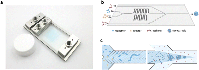
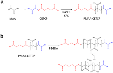
In this study, a microfluidic device was fabricated using Fluorolink MD-700 to enhance the chemical resistance and minimize solute absorption of the device (Fig. 1a). The chip was designed as a dual-stage platform, with one segment dedicated to polymer synthesis and the other for subsequent polymer crosslinking (Fig. 1b and S1†). The first stage featured a Y-channel configuration for the homopolymerization reaction. Here, Solution A containing the monomer, RAFT CTA, and coinitiator, along with Solution B containing the initiator, were mixed to form the “inner phase” of the subsequent fluid system. Rapid mixing of these solutions was achieved using the built-in staggered herringbone mixers (SHMs) (Fig. 1c). Next, the inner phase was directed into the second stage, which incorporated a hydrodynamic flow focusing (HFF) junction. At this junction, the inner phase rapidly mixed with the outer phase containing the crosslinker, leading to the swift diffusion of the crosslinker into the inner phase and subsequent crosslinking of polymers at the RAFT terminal ends. By tuning the relative flow rates of the inner and outer phases, the size of the NPs could be accurately controlled. Furthermore, the total bottom-up synthesis of the NPs could be performed entirely on the chip without intermediate purification.
Experimental section
Materials and reagents
Negative photoresist SU-8 3025 and positive photoresist AZ 40 XT-11D were purchased from Microchem (MA, USA) and Merck KGAs (Darmstadt, Germany) respectively. Methacrylic acid (MAA) and poly(ethylene glycol) diacrylate (PEGDA) were purchased from Tokyo Chemical Industry. MAA was filtered through an inhibitor remover column (Sigma Aldrich) prior to use. Sodium formaldehyde sulfoxylate (NaSFS) was purchased from Sigma Aldrich. 3-((((1-carboxyethyl)thio)carbonothioyl)thio)propanoic acid (CETCP) was purchased from Boron Molecular and used as received. Potassium persulfate (KPS) was purchased from Alfa Aesar and used as received.Physical characterizations using NMR, DLS, SEM and TEM
1H NMR monomer conversions were determined via Nuclear Magnetic Resonance spectroscopy on a Bruker Avance III HD 400 MHz using D2O as the solvent. All spectra were referenced to H2O (4.70 ppm).Polymer molecular weights were estimated using Diffusion-ordered spectroscopy (DOSY) on a Bruker Avance 500 MHz using D2O as the solvent. All experiments were performed at 25 ± 0.1 °C. Each sample was prepared at a concentration of 1 mg mL−1 while the NMR tubes contained 0.5 mL of the sample solution. 1D 1H NMR spectra were first obtained to optimize the diffusion delay time and diffusion gradient pulse length of each sample. The pulse program used was the Bruker ledbpgp2s, which was left unmodified. DOSY spectra were processed with Topspin 3.6.1 software. The molecular weights of the polymers were estimated from a calibration curve produced from poly(ethylene glycol) (PEG) molecular weight standards with the following molecular weights: 405 g mol−1, 1440 g mol−1, 3810 g mol−1, and 9920 g mol−1 (Fig. S2†).
Dynamic light scattering (DLS) studies were performed using a Malvern Zetasizer Ultra to measure the hydrodynamic diameter of the polymer NPs. Measurements were performed at a fixed scattering angle of 173° at a temperature of 25 °C. The samples were prepared at a concentration of 1 mg mL−1 in DI water and sonicated prior to analysis.
Scanning electron microscopy (SEM) was performed using a Thermo Fisher Scientific Phenom Pharos at an accelerating voltage of 15 kV. SEM images were taken with the secondary electron detector (SED). Samples were prepared by dropping a 1 mg mL−1 aqueous solution of the polymer sample onto an aluminum sample holder and oven-drying at 60 °C.
Transmission electron microscopy (TEM) was performed with a JEOL JEM-ARM300F2 operating at 200 kV and equipped with a Gatan 1k CCD camera. A 2 μL drop of 1 mg mL−1 solution of polymer in DI water was dropped onto a carbon-coated copper grid and dried at room temperature.
Microfluidic chip fabrication
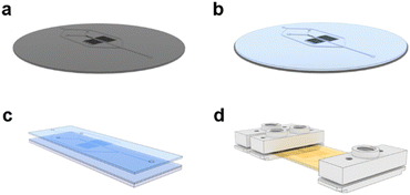
A photolithography process on silicon wafers was adapted from the literature to produce a reusable, master mold for the microfluidic chips (Fig. 2a).24 A photocurable resin was prepared with a 4 wt% composition of Darocur 1173 in Fluorolink MD700 and mixed thoroughly with a homogenizer. 5 mL of this prepared solution was poured onto the wafer and degassed until no bubbles remained (Fig. 2b). The wafer was then spin-coated at 100 rpm for 40 s to form a layer with a thickness of 270 μm. The wafer was purged with N2 gas inside a UV chamber for 5 min before irradiating it for 30 s at 350 nm. The MD700 layer was then peeled from the master and holes were punched for the inlets and outlet. A second MD700 film was prepared on a 25 × 75 mm glass slide by spin-coating 500 μL of the resin at 100 rpm for 40 s. The film containing the replica of the microfluidic channels was placed on top of the film on the glass slide (Fig. 2c). Another glass slide was placed on top and clamped with binders to sandwich the MD700 films under pressure. The films were irradiated for another 5 min to crosslink them together and over-expose the photoinitiator. The chip was further passivated by baking on a hotplate at 200 °C for 2 h. At this temperature, unreacted MD700 self-polymerizes while Darocur 1173 decomposes. Custom-made inlet and outlet ports were screwed onto the chip to secure tube fittings (Fig. 2d). The channels were successively flushed with isopropyl alcohol and DI H2O before use.Homopolymer RAFT polymerization
Monomer and initiator solutions were prepared such that the reactants were maintained at a 50![[thin space (1/6-em)]](https://www.rsc.org/images/entities/char_2009.gif) :
:![[thin space (1/6-em)]](https://www.rsc.org/images/entities/char_2009.gif) 1
1![[thin space (1/6-em)]](https://www.rsc.org/images/entities/char_2009.gif) :
:![[thin space (1/6-em)]](https://www.rsc.org/images/entities/char_2009.gif) 1
1![[thin space (1/6-em)]](https://www.rsc.org/images/entities/char_2009.gif) :
:![[thin space (1/6-em)]](https://www.rsc.org/images/entities/char_2009.gif) 1 ratio of [monomer]
1 ratio of [monomer]![[thin space (1/6-em)]](https://www.rsc.org/images/entities/char_2009.gif) :
:![[thin space (1/6-em)]](https://www.rsc.org/images/entities/char_2009.gif) [CTA]
[CTA]![[thin space (1/6-em)]](https://www.rsc.org/images/entities/char_2009.gif) :
:![[thin space (1/6-em)]](https://www.rsc.org/images/entities/char_2009.gif) [initiator]
[initiator]![[thin space (1/6-em)]](https://www.rsc.org/images/entities/char_2009.gif) :
:![[thin space (1/6-em)]](https://www.rsc.org/images/entities/char_2009.gif) [coinitiator] and with a monomer concentration of 1.5 M. In the case of MAA, the monomer solution was prepared by first dissolving CETCP (9.3 mg, 0.0367 mmol) in 155 μL of MAA (158.1 mg, 1.83 mmol) since CETCP has higher solubility in MAA than in water. DI H2O (865.6 μL) and NaSFS (5.7 mg, 0.0367 mmol) were then added after the CETCP had dissolved. The initiator solution was prepared by dissolving KPS (9.9 mg, 0.0367 mmol) in DI H2O (1200 μL). A third solution of hydroquinone (5.5 mg, 0.05 mmol) was prepared in 5 mL of DI H2O. The monomer and initiator solutions were then purged with N2 gas for 20 min before being transferred into 2.5 mL Hamilton glass gas-tight syringes that were fitted with PTFE tubing.
[coinitiator] and with a monomer concentration of 1.5 M. In the case of MAA, the monomer solution was prepared by first dissolving CETCP (9.3 mg, 0.0367 mmol) in 155 μL of MAA (158.1 mg, 1.83 mmol) since CETCP has higher solubility in MAA than in water. DI H2O (865.6 μL) and NaSFS (5.7 mg, 0.0367 mmol) were then added after the CETCP had dissolved. The initiator solution was prepared by dissolving KPS (9.9 mg, 0.0367 mmol) in DI H2O (1200 μL). A third solution of hydroquinone (5.5 mg, 0.05 mmol) was prepared in 5 mL of DI H2O. The monomer and initiator solutions were then purged with N2 gas for 20 min before being transferred into 2.5 mL Hamilton glass gas-tight syringes that were fitted with PTFE tubing.
The syringes containing the monomer and initiator solutions were plugged into the inner phase inlets of the microfluidic chip while the syringe containing hydroquinone was plugged into the outer phase inlet. Another PTFE tube was plugged into the outlet for sample collection. All three solutions were injected at similar flow rates for homopolymer synthesis at room temperature (∼23–26 °C) (Fig. 3a). A small amount of the crude products was set aside for NMR characterization while the rest were purified via dialysis against dialysis membranes with a 1k MWCO.
Nanoparticle synthesis
For the NP synthesis, the monomer and initiator solutions were prepared similarly to the solutions for the homopolymer RAFT polymerization described previously. However, the hydroquinone solution was replaced with 0.1% v/v PEGDA in DI H2O. The monomer and initiator solutions were injected at a total flow rate of 10 μL min−1 while the PEGDA solution was injected at a starting flow rate of 100 μL min−1 to give an FRR of 10. Over time, the PEGDA solution flow rate was increased while keeping the polymer solution flow rate constant until a final FRR of 20 was reached. Products from different FRRs were collected via the PTFE tube plugged into the outlet. The NPs were purified via dialysis against dialysis tubes with a 10k MWCO dialysis membrane.Results and discussion
Design and characterization of microfluidic chip
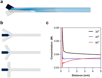
In designing a microfluidic chip with integrated polymer synthesis and post-crosslinking, SHMs were considered for polymerization while hydrodynamic flow focusing was used for crosslinking. Numerical simulations using the CFD and microfluidics modules of COMSOL were used to optimize and validate the designs before the final fabrication of the silicon masters. The numerical simulation of the SHMs was performed with a total flow rate of 10 μL min−1, the diffusion constant of the solute was set to 1 × 10⁻⁹ m2 s−1, and its concentration was set to 1 M. The simulation indicated that rapid mixing could be rapidly achieved by the passive mixer (Fig. 4a).The most significant consideration for the HFF junction was the flow focusing angle. HFF is known for rapidly mixing miscible solutions. This has made it useful for solvent replacement processes such as nanoprecipitation. Thus, the flow focusing angle must be carefully considered to minimize the mixing time of the polymer with the crosslinker. For the numerical simulations, the concentration of the polymer was set to 10 mM, assuming the full conversion of the monomer with a degree of polymerization of 50. The diffusion constant of the polymer was set to 1 × 10⁻¹⁰, as determined by 1H-NMR DOSY experiments. The simulations were performed with flow focusing angles of 30°, 45°, and 90° (Fig. 4b). The concentration profile of the polymer was analyzed from the junction until a distance of 5 mm (Fig. 4c). It can be seen that increasing the flow focusing angle decreases the mixing time of the solutions. Although the 90° junction rapidly diluted the polymers, it eventually reached a similar concentration as the 45° junction. This is because the fluid pressure from the outer phase is concentrated at the area of the polymer solution directly at the junction. On the other hand, the angled junctions spread the pressure over a longer distance. The 45° angle was thus chosen since it could rapidly and stably reach a low concentration.
Homopolymer RAFT polymerization
The properties of the single chain polymers are an important influence on the final properties of the NPs. For example, it is known that pH-responsive polymers undergo varying degrees of swelling depending on their molecular weight.25 To ensure the consistency of the quality of the synthesized homopolymers, these were initially synthesized at different flow rates in the absence of the crosslinker at the junction. Here, the crosslinker was replaced with hydroquinone in the outer phase to immediately quench the polymerization at the HFF junction.The homopolymer synthesis was performed at total flow rates of 4, 6, 8, 10, 20, 40, and 60 μL min−1. These were equivalent to residence times of 71, 48, 36, 29, 14, 7, and 5 s respectively. Here, the monomer and initiator solutions were injected through the inner Y-channel to be mixed by the SHMs (Fig. 5a). Notably, the polymerization using thermally-cured chip reached a monomer conversion of 90% in 9 s and a maximum conversion of 97% in 29 s (Fig. 5b). Next, the effect of thermally curing the chip was further investigated by comparing the monomer conversions at the flow rates of 10, 20, 40, and 60 μL min−1 with the identical experimental conditions. It was found that when using the untreated chip, the monomer conversions significantly decreased by 43% to 56% when compared to the experiments performed using thermally-treated one (Fig. 5b). Meanwhile, the conversion also dropped from 57% to 43% as the residence time increased from 5 to 29 s. This further suggests that prolonged interaction with the untreated chip may have a detrimental effect on the reaction. We suspect that because the MD700 film is fabricated by a free-radical polymerization, the presence of the unreacted monomer or initiator may compete with the on-chip free-radical polymerization.
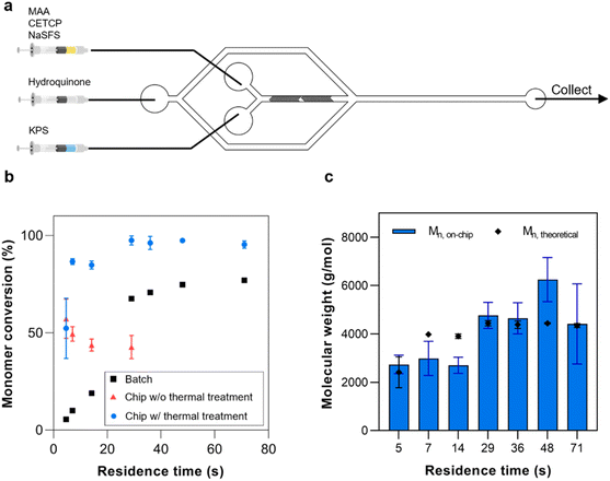 | ||
| Fig. 5 (a) Microfluidic reactor setup for PMAA homopolymer synthesis. (b) Comparison of monomer conversion rates between polymers synthesized on-chip with and without thermal treatment and in batch. Monomer conversion data were analyzed by the 1H NMR. The representative NMR spectra for the on-chip and in bulk synthesis are shown in Fig. S4 and S5† respectively. (c) Molecular weights of the polymers obtained by microfluidic synthesis compared to the theoretical molecular weights. Polymer molecular weights obtained by 2D DOSY experiment. | ||
Specific evidence of the interaction between the unreacted materials with the polymerization reaction system was unavailable. However, our UV-vis characterizations revealed that a substantial level of the unreacted photoinitiator, Darocur 1173, remained in the chip without thermal treatment since its absorbance peak at ∼250 nm could still be observed (Fig. S2†). This peak then became negligible after thermal treatment, implying the photoinitiator was degraded. To support this notion, Darocur 1173 leaching was also observed from crosslinked silica-acrylate films at acidic pH in another study.26 Thus, Darocur 1173 leaching from the untreated chip could be possible. Meanwhile, MD700 still displays a small degree of swelling when in contact with organic liquids.19 It is thus also likely that some amount of MD700 monomer to be released upon swelling in the same manner as PDMS and other crosslinked acrylate films.27,28 Although the thermal curing resulted in an approximately two-fold increase in monomer conversion in this study, it is noted that in previous studies from literature, such limitations from the presence of unreacted MD700 or photoinitiator were not observed or considered. Thus whether or not other classes of chemical reactions in MD700 chips may also benefit from thermal treatment requires further investigation.27,28
The on-chip polymerization was subsequently compared to the batch synthesis of the polymers at the equivalent residence times (Fig. 5b). The known volume of the chip and fluid flow rates were used to determine the residence time so that these could be applied to the batch polymerization. Compared to the on-chip synthesis, only a 77% monomer conversion was reached after 71 s. While the batch polymerization only achieved a conversion of 65% after 29 s, the on-chip polymerization had already achieved a 95% conversion. This demonstrates the remarkably faster reaction kinetics of flow synthesis compared to the equivalent batch reactions. Based on the literature, this rate enhancement is typically attributed to, among other factors, the difference in mixing rates19 and shorter transport path length in microreactors compared to batch reactors, wherein the small dimensions of the microreactor allow reactants to travel shorter distances before meeting.29 For example, Diehl reported a four-fold increase in reaction kinetics in a tubular microreactor,30 while Kundu reported that the reaction kinetics in a microfluidic chip increased by a minimum of one magnitude in order.31 Subsequently, 2D DOSY was then used to estimate the molecular weights of the polymers and compare them to the theoretical values (Fig. 5c and S3†). The polymers synthesized at residence times between 20 and 40 s were in good agreement with the theoretical molecular weights. However, relatively larger deviations were observed at either longer or shorter residence times. A plausible explanation is that at longer residence times, the polymers were at times observed to settle in the chip to some degree. It is thus possible that this added some variance to the properties of the collected polymers. At the short residence times, simulations suggest that these can result in lower mixing efficiency.32 Therefore a residence time between 20–40 s would be the ideal range to operate this chip.
Next, the behavior of the crosslinker at the HFF junction was studied by varying the concentration of PEGDA among 0.1, 0.5, and 1.0% v/v at a flow rate ratio (FRR) of 14. The flow rate of the polymer reaction mixture was kept constant at 10 μL min−1. This flow rate was chosen since it gave a suitable balance between yield, residence time, and internal chip pressure. At a concentration of 0.1% v/v (Fig. S6a†), the flow focusing at the HFF junction could be clearly seen without any visible precipitation. Above this concentration, however, the polymers could be seen precipitating around the focused stream of the polymer solution (Fig. S6b and c†). Furthermore, the degree of precipitation increased directly with the PEGDA concentration. At 0.50 and 1.0% v/v of PEGDA, the NPs could not be recovered downstream for further analysis. Thus, a concentration of 0.1% v/v PEGDA was used for the rest of the study.
Nanogel synthesis by HFF and crosslinking
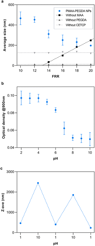
Nanogel synthesis was performed by flowing a 0.1% v/v solution of PEGDA in the outer phase to crosslink the polymers at the HFF junction. Based solely on the monomer conversion, any of the experimental flow rates were suitable for the synthesis of NPs. An inner phase flow rate of 10 μL min−1 was chosen since it gave an acceptable balance of yield and high-pressure stability, as excessively high flow rates risk fluid backflow or chip delamination. The flow rate ratio (FRR) was varied from 10 to 20 to study the effect of the FRR on the size of the resulting NPs (Fig. 6a). As the FRR was increased, the results showed an inversely proportional relationship to NP size. At the current conditions, the NP size could be controlled from 200–550 nm by tuning the FRR. This is the main advantage of HFF. Compression of the inner phase increases with the outer phase flow rate, thus decreasing the width of the focused fluid. Consequently, solutes from the outer phase need to diffuse a shorter length to completely mix with the inner phase at higher FRR. This rapid mixing results in the formation of small NPs.30To ensure the reliability of this approach and get a mechanistic understanding, control studies were conducted, each having a reactant removed from the system. When the crosslinker was removed, the results showed that there were no NPs being formed. Interestingly, removing the monomer had the opposite effect on the NP size as the complete reaction. In this case, it is reasoned that the increasing size of the NPs was simply a consequence of the stoichiometric amounts of the accessible crosslinkers and initiators at the HFF junction. As the FRR was increased, the amount of crosslinker relative to the initiator also increased, leading to larger particles. Additionally, since the crosslinker was not in the inner phase, it was not subjected to HFF. Something that was not expected was the production of similarly sized NPs when the RAFT CTA was removed from the system. Theoretically, the crosslinker should not be able to further react with the homopolymer in the absence of the RAFT CTA unless the free-radical polymerization has yet to be terminated at the HFF junction. If that is the case, this implies that the RAFT CTA has some additional influence on the NP formation other than the subsequent crosslinking. Further work will be required to fully understand its influence.
To demonstrate the potential of the NPs for therapeutic applications, their properties were studied at different pH since MAA is a well-studied pH-responsive monomer. As expected, the NPs retained the pH-responsive properties of MAA. Below the pKa of MAA at pH 4.5, the carboxylic acid groups are fully protonated while they are fully ionized at basic pH (Fig. 6b).33 The loss of the ionic interactions with water at low pH result in an increase in hydrophobicity of the NPs. This caused them to aggregate and increase the turbidity of the solution. This resulted in a high optical density at low pH. At higher pH, the turbidity decreased due to the ionization of the carboxylic acid groups. Additionally, the reversibility of the pH-response was studied by repeatedly changing the pH of the solution between pH 1 and 10 (Fig. 6c).
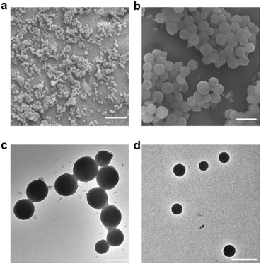
Electron microscopy images were obtained to further confirm the synthesis of the nanogel particles. SEM images of the NPs synthesized at FRR10 at different magnification show that the NPs have formed distinct spherical particles (Fig. 7a and b). Furthermore, TEM images of the NPs formed at FRR10 (Fig. 7c) and at FRR20 (Fig. 7d) show the difference in particle size obtained when the FRR is controlled.
Conclusions
We have developed a microfluidic chip-based platform for the bottom-up synthesis of polymer NPs. This was achieved by fabricating the chip from a PFPE to give it high chemical resistance and low absorption, then thermally passivating it to prevent the inhibition of RAFT polymerization by unreacted MD700 and photoinitiator in the chip. Exclusion of thermal passivation resulted in the inhibition of the reaction, which aggravated as the residence time of the reaction increased. Since this has not been observed in non-polymerization reactions, further studies are required to elucidate the inhibition mechanism and understand its implications for other on-chip reactions. Furthermore, the chip-based platform was demonstrated to synthesize polymers at higher rates than batch synthesis. Towards the synthesis of polymer NPs, these could be synthesized with size control in a facile manner. The size of the NPs could be tailored by changing the relative flow rate between the solutions. Finally, the synthesized NPs retained the pH-responsive properties of the homopolymers. Further studies are being conducted to test the incorporation of other polymerization reactions using different monomers and RAFT agents, as well as to evaluate the therapeutic effects of these synthesized polymer NPs.Author contributions
R. C. K. Montalbo and H.-L. Tu designed the research; R. C. K. Montalbo performed the experiments and analyzed the data. M.-J. Wu performed experiments and assisted in data analysis; R. C. K. Montalbo and H.-L. Tu wrote the initial draft. R. C. K. Montalbo and H.-L. Tu contributed to the editing of the manuscript. H.-L. Tu conceived and supervised the project, and acquired the funding.Conflicts of interest
There are no conflicts to declare.Acknowledgements
We thank the funding support from the National Science and Technology Council (former Ministry of Science and Technology) in Taiwan: MOST 110-2113-M-001-019-MY2 and NSTC 112-2628-M-001-004-MY3. We also thank Dr Sofani Gebreyesus and the Advanced Nano/Micro Fabrication and Characterization Laboratory at the Institute of Physics (Academia Sinica) for the support and assistance in using photolithography equipment for the fabrication of silicon master molds. We thank Dr Pai-Chia Kuo of the Advanced Materials Characterization laboratory, Institute of Atomic & Molecular Sciences (Academia Sinica) for the technical support in acquiring the TEM images.Notes and references
- F. F. Meng, J. P. Wang, Y. Y. He, G. M. Cresswell, N. A. Lanman, L. T. Lyle, T. L. Ratliff and Y. Yeo, Proc. Natl. Acad. Sci. U. S. A., 2022, 119 Search PubMed.
- Y. C. Yang, M. H. Liu, S. M. Yang and Y. H. Chan, ACS Sens., 2021, 6, 4255–4264 CrossRef CAS PubMed.
- C. Yin, X. Y. Tai, X. Z. Li, J. H. Tan, C. S. Lee, P. F. Sun, Q. L. Fan and W. Huang, Chem. Eng. J., 2022, 428, 132098 CrossRef CAS.
- S. Z. Li, G. Han and W. Q. Zhang, Polym. Chem., 2020, 11, 4681–4692 RSC.
- T. Junkers, Macromol. Chem. Phys., 2017, 218, 1600421 CrossRef.
- S. Bazban-Shotorbani, E. Dashtimoghadam, A. Karkhaneh, M. M. Hasani-Sadrabadi and K. I. Jacob, Langmuir, 2016, 32, 4996–5003 CrossRef CAS PubMed.
- Z. Mahmoudi, J. Mohammadnejad, S. R. Bazaz, A. A. Mehrizi, M. Saidijam, R. Dinarvand, M. E. Warkiani and M. Soleimani, Carbohydr. Polym., 2020, 229, 115551 CrossRef CAS PubMed.
- Y. Yuan, J. Gao, Y. Z. Zhai, D. C. Li, C. L. Fu and Y. Huang, Carbohydr. Polym., 2022, 287, 119331 CrossRef CAS PubMed.
- Z. Whiteley, G. Massaro, G. Gkogkos, A. Gavriilidis, S. N. Waddington, A. A. Rahim and D. Q. M. Craig, Nanoscale, 2023, 15, 5865–5876 RSC.
- R. C. S. Bicudo and M. H. A. Santana, Chem. Eng. Sci., 2012, 84, 134–141 CrossRef CAS.
- N. Zaquen, H. J. Zu, A. Kadir, T. Junkers, P. B. Zetterlund and C. Boyer, ACS Appl. Polym. Mater., 2019, 1, 1251–1256 CrossRef CAS.
- H. Phan, V. Taresco, J. Penelle and B. Couturaud, Biomater. Sci., 2021, 9, 38–50 RSC.
- E. Baeten, S. Vanslambrouck, C. Jérôme, P. Lecomte and T. Junkers, Eur. Polym. J., 2016, 80, 208–218 CrossRef CAS.
- S. Kim, J. Kim, Y. H. Joung, J. Choi and C. Koo, Micromachines, 2018, 9, 639 CrossRef PubMed.
- N. Zaquen, M. Rubens, N. Corrigan, J. T. Xu, P. B. Zetterlund, C. Boyer and T. Junkers, Prog. Polym. Sci., 2020, 107, 101256 CrossRef CAS.
- J. N. Lee, C. Park and G. M. Whitesides, Anal. Chem., 2003, 75, 6544–6554 CrossRef CAS PubMed.
- A. Priola, R. Bongiovanni, G. Malucelli, A. Pollicino, C. Tonelli and G. Simeone, Macromol. Chem. Phys., 1997, 198, 1893–1907 CrossRef CAS.
- J. P. Rolland, R. M. Van Dam, D. A. Schorzman, S. R. Quake and J. M. DeSimone, J. Am. Chem. Soc., 2004, 126, 2322–2323 CrossRef CAS PubMed.
- J. O. Kim, H. Kim, D. H. Ko, K. I. Min, D. J. Im, S. Y. Park and D. P. Kim, Lab Chip, 2014, 14, 4270–4276 RSC.
- C. Bonneaud, J. Howell, R. Bongiovanni, C. Joly-Duhamel and C. M. Friesen, Macromolecules, 2021, 54, 521–550 CrossRef CAS.
- H. H. Jeong, S. H. Han, S. Yadavali, J. Kim, D. Issadore and D. Lee, Chem. Mater., 2018, 30, 2583–2588 CrossRef CAS.
- F. Kotz, P. Risch, D. Helmer and B. E. Rapp, Micromachines, 2018, 9, 115 CrossRef PubMed.
- A. Goralczyk, F. Mayoussi, M. Sanjaya, S. F. Corredor, S. Bhagwat, Q. C. Song, S. Schwenteck, A. Warmbold, P. Pezeshkpour and B. E. Rapp, Chem. Ing. Tech., 2022, 94, 975–982 CrossRef CAS PubMed.
- A. D. Stroock, S. K. W. Dertinger, A. Ajdari, I. Mezic, H. A. Stone and G. M. Whitesides, Science, 2002, 295, 647–651 CrossRef CAS PubMed.
- T. Swift, L. Swanson, M. Geoghegan and S. Rimmer, Soft Matter, 2016, 12, 2542–2549 RSC.
- S. Ouali, Y. Louis, P. Germain, R. Gourdon and V. Desjardin, J. Polym. Environ., 2018, 26, 244–253 CrossRef CAS.
- X. Wei, Y. Pan, M. J. Wang, Y. H. Wang, H. L. Lin, L. Jiang, D. H. Lin and H. Cheng, Clin. Oral Investig., 2022, 26, 2887–2898 CrossRef PubMed.
- K. J. Regehr, M. Domenech, J. T. Koepsel, K. C. Carver, S. J. Ellison-Zelski, W. L. Murphy, L. A. Schuler, E. T. Alarid and D. J. Beebe, Lab Chip, 2009, 9, 2132–2139 RSC.
- M. W. Losey, M. A. Schmidt and K. F. Jensen, Ind. Eng. Chem. Res., 2001, 40, 2555–2562 CrossRef CAS.
- C. Diehl, P. Laurino, N. Azzouz and P. H. Seeberger, Macromolecules, 2010, 43, 10311–10314 CrossRef CAS.
- S. Kundu, A. S. Bhangale, W. E. Wallace, K. M. Flynn, C. M. Guttman, R. A. Gross and K. L. Beers, J. Am. Chem. Soc., 2011, 133, 6006–6011 CrossRef CAS PubMed.
- B. Hama, G. Mahajan, P. S. Fodor, M. Kaufman and C. R. Kothapalli, Microfluid. Nanofluid., 2018, 22, 54 CrossRef.
- J. P. Best, M. P. Neubauer, S. Javed, H. H. Dam, A. Fery and F. Caruso, Langmuir, 2013, 29, 9814–9823 CrossRef CAS PubMed.
Footnote |
| † Electronic supplementary information (ESI) available. See DOI: https://doi.org/10.1039/d4ra01956c |
| This journal is © The Royal Society of Chemistry 2024 |

