 Open Access Article
Microrail-assisted liposome trapping and aligning in microfluidic channels†
Shun Okada and
Kan Shoji *
*
Department of Mechanical Engineering, Nagaoka University of Technology, 1603-1 Kamitomioka, Nagaoka, Niigata 940-2188, Japan. E-mail: kshoji@mech.nagaokaut.ac.jp
First published on 5th June 2024
Abstract
Liposome assemblies with a specific shape are potential cell tissue models for studying intercellular communication. Microfluidic channels that can trap liposomes have been constructed to achieve efficient and high-throughput manipulation and observation of liposomes. However, the trapping and alignment of multiple liposomes in a specific space are still challenging because the liposomes are soft and easily ruptured. In this study, we focused on a microrail-assisted technique for manipulating water-in-oil (w/o) emulsions. In this technique, w/o emulsions are trapped under the microrails through a surface energy gradient. First, we investigated whether the microrail channel can be applied for liposome trapping and alignment and found that the numerical simulations showed that drag forces in the direction of the microrail acted on the liposomes, thereby moving the liposomes from the main channel to the microrail. Next, we designed a microrail device based on the simulation results and trapped liposomes using the device. Resultantly, 24.7 ± 8.5 liposomes were aligned under the microrail within an hour, and the microrail was filled with liposomes for 3 hours. Finally, we prepared the microrail devices with y-shaped and ring-shaped microrails and demonstrated the construction of liposome assemblies with specific shapes, not only the straight shape. Our results indicate that the microrail-assisted technique is a valuable method for manipulating liposomes because it has the potential to provide various-shaped liposome assemblies. We believe the microrail channel will be a powerful tool for constructing liposome-based cell–cell interaction models.
1 Introduction
Cell-sized lipid vesicles have been frequently studied in cellular models as because of cell-like characteristics they can reproduce by encapsulating biomolecules and functionalizing the phospholipid membrane. For example, the development of cell-like functions, such as in vitro transcription and translation,1–3 RNA and DNA replication,4–6 and cytoskeletal networks7–11 were achieved in lipid vesicles. Recent studies have used lipid vesicles as the platform for the construction of cellular tissue models on local cell-to-cell communication, including prey and predator relationships,12,13 communication between two lipid vesicles,14–16 and quorum sensing communication.17 In these studies, water-in-oil (w/o) emulsions and liposomes were utilized.To improve the stochastic analysis throughput and reduce the sample volume for lipid vesicle experiments, microfluidic channels that can manipulate and trap lipid vesicles in a specific space have been developed18–24 based on microfluidic droplet manipulation technologies.25–27 For the manipulation of w/o emulsions, numerous microfluidic channels that can manipulate multiple w/o emulsions and prepare w/o emulsion assemblies with specific shapes were developed.28–30 For example, Schlicht and Zagnoni31 succeeded in trapping multiple w/o emulsion in series and aligning droplet interface bilayers (DIBs) in a microfluidic channel. Elani et al.32 developed a microchannel that can form two- and three-dimensional DIB networks.
On the other hand, because the liposomes easily deform and rupture, constructing liposome assemblies with specific shapes is still challenging, although the manipulation of single,18,33 a few,34,35 or numerous liposomes36 has been achieved. For example, Sugahara et al.34 succeeded in trapping two liposomes next to each other using a microfluidic channel composed of trapping and bypass channels. Yandrapalli and Robinson36 developed a microchannel with physical trapping structures that can trap multiple liposomes to form large assemblies after trapping approximately 140 liposomes. If techniques for the construction of liposome assemblies with a specific shape are developed, the construction of liposome-based cellular tissue models that are more similar to living cells than w/o emulsion-based ones are achieved because of the differences relating to lipid membranes in w/o emulsions and liposomes. Although cells are surrounded by a lipid bilayer, w/o emulsions are surrounded by a lipid monolayer formed at the interface between the aqueous solution and oil. Thus, the communication between w/o emulsions is performed through the lipid bilayer formed by contacting the emulsions. In other words, the communication imitates communications between inside and outside cells and does not replicate cell-to-cell communications. Additionally, because the outside of w/o emulsions is oil, w/o emulsions cannot communicate with the external environment. On the other hand, because liposomes are lipid vesicles surrounded by lipid bilayers, just like cells, liposome assemblies can replicate intercellular communications through two lipid bilayers, as well as communications with the external environment.
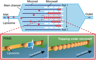
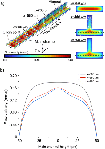
Here, we focus on a microrail channel prepared by constructing micro-scaled grooves on the top of the channels to trap and align multiple w/o emulsions in a row and construct DIB networks.37–39 For example, Abbyad et al.37 reported a method of aligning w/o emulsion in a row with microrail. Based on this technique, Carreras et al.38 succeeded in DIB formation on the microrail and propagation of a chemical signal between w/o emulsions. In this channel, w/o emulsions are vertically squeezed and thus have high surface energy, which was defined as their surface tension multiplied by their surface area. When the w/o emulsions encounter a microrail, their surface energy is reduced because they partly enter the groove and deform, and then they are trapped under the microrail by attraction force generated by the surface energy gradient. Finally, w/o emulsions move down by flow-generated force and are stacked in a row at the end of the microrail. If the microrail channel can be applied to manipulate liposomes, a liposome manipulation system can be developed to align liposomes in arbitrary shapes. In this study, we investigated whether the microrail channel can be applied for liposome manipulation. First, we analyzed the flow distribution and liposome behaviors in the microrail channel using computational fluid dynamics (CFD) simulations and described the trapping mechanism of liposomes in the microrail. Then, we designed the microrail device based on the CFD simulations and trapped and aligned liposomes using the channel (Fig. 1).
2 Experimental
2.1 Reagents and chemicals
Oil/lipid mixtures were prepared using 1,2-dioleoyl-sn-glycero-3-phosphocholine (DOPC; Avanti Polar Lipid, Inc., Alabaster, AL, USA), cholesterol (Chol; Avanti Polar Lipid, Inc.), and mineral oil (Sigma-Aldrich Co., St. Louis, MO, USA). 1,2-Dioleoyl-sn-glycero-3-phosphoethanolamine-N-(lissamine rhodamine B sulfonyl) (ammonium salt) (18![[thin space (1/6-em)]](https://www.rsc.org/images/entities/char_2009.gif) :
:![[thin space (1/6-em)]](https://www.rsc.org/images/entities/char_2009.gif) 1 Liss Rhod PE; Avanti Polar Lipid, Inc.) was added to the oil/lipid mixture when preparing liposomes for fluorescent observations. Inner and outer solutions were prepared by dissolving sucrose and glucose (FUJIFILM Wako Pure Chemical Co., Osaka, Japan) and calcein (Tokyo Chemical Industry Co. Ltd, Tokyo, Japan), respectively, in ultrapure water purified with a Milli-Q system (Direct-Q UV; Merck Millipore Co., Burlington, MA, USA) at 18.2 MΩ at 25 °C. SU-8 3005, SU-8 3025, and SU-8 3050 (KAYAKU Advanced Materials, Inc., Westborough, MA, USA) were used as photoresists. Polydimethylsiloxane (PDMS; SILPOT 184, Dow Toray Co., Ltd, Tokyo, Japan) was used as the material for constructing the microchannels.
1 Liss Rhod PE; Avanti Polar Lipid, Inc.) was added to the oil/lipid mixture when preparing liposomes for fluorescent observations. Inner and outer solutions were prepared by dissolving sucrose and glucose (FUJIFILM Wako Pure Chemical Co., Osaka, Japan) and calcein (Tokyo Chemical Industry Co. Ltd, Tokyo, Japan), respectively, in ultrapure water purified with a Milli-Q system (Direct-Q UV; Merck Millipore Co., Burlington, MA, USA) at 18.2 MΩ at 25 °C. SU-8 3005, SU-8 3025, and SU-8 3050 (KAYAKU Advanced Materials, Inc., Westborough, MA, USA) were used as photoresists. Polydimethylsiloxane (PDMS; SILPOT 184, Dow Toray Co., Ltd, Tokyo, Japan) was used as the material for constructing the microchannels.
2.2 Simulation of microfluidic channels
To understand the flow distributions and liposome trajectories in the microrail channels, three-dimensional CFD simulations were performed using COMSOL Multiphysics 6.0 software (COMSOL Inc., Stockholm, Sweden). A no-slip boundary condition was assumed at the wall–liquid interface. The flow conditions were set as water laminar flow. The entrance flow rate was 0.1 mm s−1, and the outlet pressure was 0 Pa. The diameter of particle was set to 15 μm.2.3 Preparation of microfluidic channels
The microfluidic channels were designed using AutoCAD 2023 (Autodesk, Inc., San Rafael, CA, USA). The SU-8 molds of microfluidic devices, which consisted of the main channel, microrails, and walls, were fabricated by multiple-step photolithography because the microrail layer was placed on the main channel layer. UV light exposure was performed using a mask aligner (MA-20, MIKASA Co., Ltd, Tokyo, Japan). The channels were fabricated using the PDMS molding and bonded to cover glasses using a plasma cleaner (PDC-32 G, Harrick Plasma, Ithaca, NY, USA) (Fig. S1†). The 200 μL pipette tip was inserted at the inlet of the device as a sample reservoir.2.4 Microfluidic trapping of liposomes
The liposomes were prepared using the w/o emulsion transfer method40 (see Section S1 and Fig. S2†). The liposome solution was infused in the microchannel by aspirating from the outlet with a syringe pump (YSP-202, YMC Co., Ltd, Kyoto, Japan). The microchannels were observed using an inverted fluorescence microscope (Ts2, Nikon Corporation, Tokyo, Japan) with a digital camera (WRAYCAM-VEX120, WRAYMER Inc., Osaka, Japan). The z-stack images of trapped liposomes were acquired by all-in-one microscopy (BZ-X810, Keyence Co., Osaka, Japan). All images were analyzed using ImageJ.3 Results and discussion
3.1 Investigation of liposome trapping mechanism
Additionally, we investigated the effect of the main channel height on flow distribution and found that the main flow region shifted from the main channel to the microrail when the main channel height decreased (Fig. S3 and S4†). This result is due to the resistance ratio between the main channel and the microrail (detailed discussion in Section S2†) and indicates that a lower main channel height can improve the induction rate of liposomes into the microrail, although liposomes that are larger than the height of the main channel will have difficulty entering the main channel.
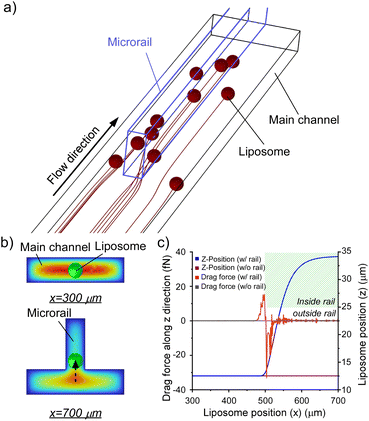
Fig. 3b and c show the displacements of the liposomes and drag forces on the liposomes flowing from the center of the inlet (x = 0 μm, y = 0 μm, and z = 12.5 μm). Resultantly, the drag force increased when the liposome approached the microrail, and the liposome was displaced in the z-direction upon approaching the microrail and was not displaced in the y-direction (Fig. 3b and S6a†). Since the direction of droplet displacement was the same as that of the cross-sectional flow observed around the tip of the microrail, the cross-sectional flow thus caused droplet displacement. When the liposome moved under the microrail, the drag force then decreased and became negative. After that, the drag force returned to zero, and the z-position of the liposome became stable again. The drag force is proportional to the difference between the fluid and liposome velocities.41 In this channel, the flow velocity of the z-direction increased when approaching the microrail, then decreased under the microrail, and finally returned to zero (Fig. S7†). Hence, the result of the calculated drag force transition is reasonable. On the other hand, when the liposome flowed in a rectangular microchannel without the microrail, the liposome flowed straight from the inlet to the outlet (Fig. S6b†), and the displacements and the drag forces in the z-direction were approximately zero because there was no flow in the z-direction (Fig. 3c).
Based on these results, we hypothesized that two different flow mechanisms under the microrail, depending on the liposome size. The first mechanism is based on the surface energy gradient (Fig. S8a†). When the liposomes are larger than the height of the main channel, the effect of the surface energy gradient is significant, as shown in previous reports.42 The second mechanism is based on drag forces (Fig. S8b†). As shown in the simulations, when the liposomes are smaller than the height of the main channel, liposomes migrate toward the microrail via the drag and lift forces caused by the flow velocity gradient. Hence, the microrail channel can potentially trap liposomes both larger and smaller than the main channel height via the two mechanisms.
3.2 Demonstration of liposome trapping and alignment
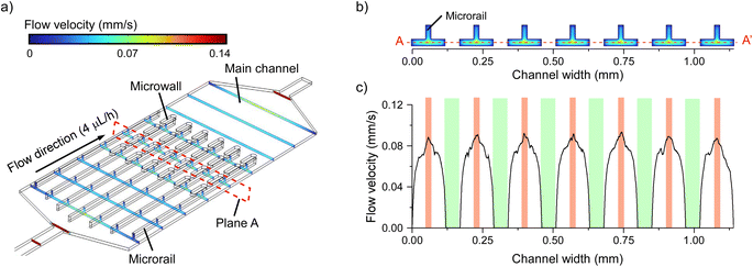
To demonstrate liposome trapping and alignment, we prepared a microfluidic device with multiple microrails. The microrail device consisted of the main channel, microrails, and microwalls (Fig. 1 and S9†). The main channel height was 25 μm, while the microrail height and width were 50 and 20 μm, respectively. Seven microrails were constructed parallel to one another at 170 μm intervals in the main channel. The microwalls were placed between microrails to diminish the high flow velocity region under the microrails.To confirm that the flow distribution in each microrail is similar to that in the simplified microrail channel model, we simulated the flow distribution in the microrail device at the flow rate of 4.0 μL h−1 (Fig. 4a). The flow distribution similar to that in the simplified microrail channel model was observed for each microrail (Fig. 4b and c). Hence, the liposomes that flow into the main channel will accumulate under each microrail.
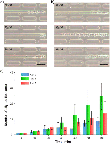
We infused liposomes into the microrail device at a flow rate of 4.0 μL h−1 and observed the liposome behaviors using a fluorescent microscope. We found that liposomes flowed under the microrails and were trapped at the end of the microrails. Then, over time, liposomes accumulated under the microrails (Fig. 5a and Movie S1†). The number of trapped liposomes was lower under the microrails far from the center of the channel (Fig. S11†). This is because the liposomes with the size that can be trapped under the microrail mainly flowed in the center of the channel. The flowing position of the liposomes was dependent on the size of the liposomes, and the larger liposomes flowed in the center of the channel. As a result, the number of trapped liposomes varied depending on the position of microrails.
To investigate the liposome-trapping characteristics of each microrail, we analyzed the number of trapped liposomes under each microrail at different time points (Fig. 5b and S12†). The time point when the first liposome was collected at the end of the microrails was defined as zero, which was used as the baseline for the time course for counting the trapped liposomes under the microrails. Since the number of trapped liposomes was lower under the microrails far from the center of the channel, we focused on the three microrails (no. 3, 4, and 5) placed around the center of the main channel. As a result, although the number of trapped liposomes sometimes decreased as the trapped liposomes were pushed out by the other liposomes flowing under the microrail, the number of trapped liposomes increased over time (Fig. 5c). After one hour, the numbers of trapped liposomes under the microrails of no. 3, 4, and 5 reached 8.7 ± 2.5, 24.7 ± 8.5, and 13.7 ± 7.6, respectively. Moreover, after flowing liposomes for three hours, the microrail was filled with 57 liposomes (Fig. S10†). Next, we investigated the trapping duration of liposomes that were trapped under the microrail for more than 1 min. As a result, the proportion of liposomes trapped for more than 30 min was 62% (n = 50). The maximum number of aligned liposomes in the microfluidic device was three in the previous study,35 whereas our device allowed for more liposomes to be aligned in a specific space than previous devices. Additionally, we evaluated the alignment of trapped liposomes. We measured the vertical positions of trapped liposomes relative to the liposome trapped at the end of the microrail. The maximum vertical distance was 9.8 μm, and all liposomes were trapped inside the microrails (Fig. S13†). From these results, we believe that our microrail device is a potentially powerful tool for aligning multiple liposomes in a row and constructing cellular tissue models.
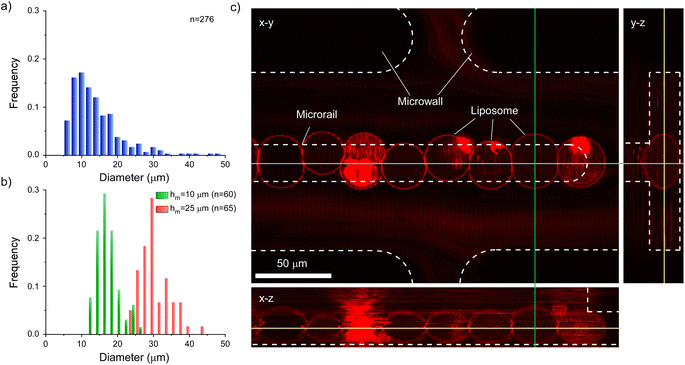
Furthermore, we analyzed the sizes and shapes of trapped liposomes to discuss the size selectivity and trapping mechanism of liposomes of the microrail device. First, we compared the diameters of prepared and trapped liposomes. The size range of prepared liposomes was 5–50 μm, whereas the diameter range of trapped liposomes was 22–44 μm, suggesting that the microrail device offered size selectivity (Fig. 6a and b). The prepared liposomes were heterogeneous in size because we used heterogeneous-sized w/o emulsions that were prepared by tapping the microtubes with the inner and lipid solutions for the formation of liposomes by the emulsion transfer method. On the other hand, the diameters of trapped liposomes were similar to the main channel height (25 μm). This result is because the liposomes with sufficiently smaller diameters flowed away and exited the channel, whereas liposomes with sufficiently larger diameters could not enter the channel. Hence, we prepared a microrail device with a lower main channel height (10 μm) and evaluated the diameters of trapped liposomes by flowing the liposomes into the device at a flow rate of 4.0 μL h−1. The diameter range of trapped liposomes was 12–26 μm (Fig. 6b), which was similar to the main channel height.
While similar trends were confirmed between the devices with main channel heights of 10 and 25 μm with respect to the diameters of trapped liposomes, significant differences were observed with respect to the linearity of the trapped liposomes. Since the diameters of most trapped liposomes were smaller than the width of the microrails (20 μm) in the microrail device with the main channel height of 10 μm, liposomes did not align in a row (Fig. S14†). Therefore, the width of the microrails must be optimized for the diameters of the trapped liposomes in order to align them in a row. Nevertheless, the size selectivity of the microrail devices is valuable for the construction of cellular tissue models. For example, membrane raft formation or the reconstitution of the actin and keratin networks is affected by the size of the observed liposomes.10,43 Although uniformly sized liposomes can be trapped in microfluidic channels by combining size-sorting and liposome-trapping channels,44 the channel design becomes complicated. Conversely, our proposed microrail device can offer both size separation and liposome trapping using just a single channel.
From these liposome-trapping characteristics of the microrail device, we investigated the mechanisms of trapping liposomes under the microrails based on liposome diameter. In the microrail devices, liposomes both smaller and larger than the main channel height were trapped, indicating that liposomes were transported under the microrails not only via the surface energy gradient but also via the drag force applied to the liposomes, as shown in the simulations. However, the proportion of liposomes that were smaller than the main channel height was much lower than that of liposomes larger than the main channel height. Hence, when the liposomes were smaller than the main channel height, even if they flowed under the microrails, most of them were not trapped at the end of the microrails or by pre-trapped liposomes.
Finally, we obtained z-stack images of the aligned liposomes to investigate their three-dimensional shapes. After aligning liposomes on the microrail, we captured images successively from the x–y planes along the z-direction using all-in-one microscopy (BZ-X810) while flowing the liposome solution. As a result, although the multi-compartment liposomes and multilamellar liposomes produced during liposome formation by the emulsion transfer method45–47 were also trapped under the microrail, the liposomes were trapped under the microrail in a row without vertical overlapping of liposomes (Fig. 6c).
Based on the images obtained, we confirmed that the trapped liposomes were deformed into a flattened shape. We initially assumed that the top of the liposomes would be deformed into a convex shape as a result of becoming trapped under the microrails. However, since the diameters of trapped liposomes were similar to the main channel height, the deformation may have been caused by the density difference between the inner and outer solutions of the liposomes. In this study, we used the inner and outer solutions with different densities to efficiently form liposomes by the emulsion taransfer method. As a result, the liposomes were initially flattened by the density difference. Although the liposomes prepared by the emulsion transfer method were frequently used as cell models,48 the deformation of liposomes can be avoided by exchanging the outer solution or preparing liposomes by other methods, such as electro-formation or microfluidic methods.49–52 Because the microfluidic channel can rapidly exchange the solution, the density difference potentially disappears by infusing the inner solution of liposomes into the channel after trapping liposomes.
Furthermore, in the microrail devices, the contact area between the channel walls and liposomes was extremely low, with the top of the liposomes in partial contact with the microrail edge. When constructing cellular tissue models with liposomes, the contact area between the channel walls and liposomes significantly influences the characteristics of the models. For example, the membrane permeability under the flow is influenced by the contact of the channel wall with the observed liposome.53 Since the microrail devices can form liposome assemblies with a low contact area between the channel walls and liposomes, we believe that the microrail devices have a promising application in the construction of cellular tissue models without any wall-induced influences.
3.3 Formation of liposome assemblies with specific shapes
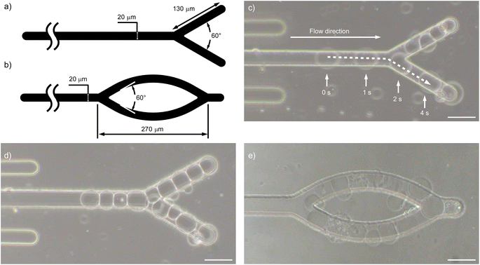
Finally, we demonstrated the formation of liposome assemblies with specific shapes using our microrail devices, not just serial alignment. We prepared the microrail devices with y-shaped and ring-shaped microrails and observed the trapping of liposomes that were infused at a flow rate of 4.0 μL h−1 (Fig. 7a, b, and S15†). As a result, liposomes flowed and were trapped under the microrails (Fig. 7c). Then, the liposome assemblies with the shapes of the microrails were constructed (Fig. 7d, e, Movies S2 and S3†). After the first liposome was trapped, the y-shaped and ring-shaped liposome assemble were constructed within 40 min and 220 min, respectively. These results indicate that our approach can provide various shaped liposome assemblies, not only the straight shape. To the best of our knowledge, this is the first work that shows the controllable shape of liposome assemblies in a microfluidic device. Previously, the construction methods of liposome assembly with a specific shape were developed based on liposome manipulation techniques with micropipettes54 and optical55 and acoustic tweezers.56 However, these techniques are usually costly and require complicated setups. On the other hand, the microfluidic-based liposome trapping technique provides various advantages, including simple setup, low cost, low reagent consumption, and potential integration with other devices. Hence, we believe that the microrail devices will be a powerful tool for preparing variously shaped cellular tissue models without any complicated and costly setups.4 Conclusions
We proposed a technique for preparing liposome assemblies with specific shapes using microrails for the construction of liposome-based cellular tissue models. The microrail-assisted liposome trapping and alignment technique allowed multiple liposomes with similar diameters to be aligned in a row under the microrail. Our simulations of flow distributions and liposome behaviors in the microrail channel showed that a cross-sectional flow from the side walls of the main channel to the microrail occurred around the tip of the microrail, resulting in the migration of liposomes under the microrail. Based on the simulation results, we developed the microrail device that consisted of seven straight microrails, the main channel, and microwalls surrounding the microrails. The liposome trapping and alignment demonstrations revealed that the liposomes flowed under and were trapped at the end of the microrails. The number of trapped liposomes increased over time, resulting in an average trapping number of 24.7 ± 8.5 liposomes within an hour. Then, after flowing the liposome solution for three hours, the microrail was filled with 57 liposomes. Furthermore, the diameters of the trapped liposomes were approximately similar to the main channel height, indicating that the microrail device can be used to regulate the sizes of trapped liposomes by changing the main channel height. Finally, we constructed y-shaped and ring-shaped liposome assemblies by changing the design of microrails. Although aligning multiple liposomes in specific shapes using previous liposome-trapping microchannels was challenging, the microrail-assisted liposome trap technique offers promising efficacy in the construction of liposome assembles with specific shapes. Hence, we believe that the microrail channel will be a powerful tool for constructing cellular tissue models through which local cell-to-cell communications can be further investigated and developed.Author contributions
K. S. conceived and designed the experiments; S. O. performed the experiments and analysis; all authors approved the final version of the manuscript.Conflicts of interest
There are no conflicts to declare.Acknowledgements
This work was supported by JSPS KAKENHI (Grant No. 23H01822), MEXT LEADER Grant, JST FOREST Program (Grant No. JPMJFR2028), JST ACT-X (Grant No. JPMJAX22K9), and The Foundation for Applied Research and Technological Uniqueness at N. U. T.References
- K. Nishimura, T. Matsuura, K. Nishimura, T. Sunami, H. Suzuki and T. Yomo, Langmuir, 2012, 28, 8426–8432 CrossRef CAS PubMed.
- S. Berhanu, T. Ueda and Y. Kuruma, Nat. Commun., 2019, 10, 1–10 CrossRef CAS PubMed.
- P. Torre, C. D. Keating and S. S. Mansy, Langmuir, 2014, 30, 5695–5699 CrossRef CAS PubMed.
- R. Mizuuchi, N. Ichihashi, K. Usui, Y. Kazuta and T. Yomo, ACS Synth. Biol., 2015, 4, 292–298 CrossRef CAS PubMed.
- P. Van Nies, I. Westerlaken, D. Blanken, M. Salas, M. Mencía and C. Danelon, Nat. Commun., 2018, 9, 1–12 CrossRef CAS PubMed.
- K. Adamala and J. W. Szostak, Science, 2013, 342, 1098–1100 CrossRef CAS PubMed.
- E. Abu Shah and K. Keren, Elife, 2014, 3, 1–15 CrossRef PubMed.
- M. Miyazaki, M. Chiba, H. Eguchi, T. Ohki and S. Ishiwata, Nat. Cell Biol., 2015, 17, 480–489 CrossRef CAS PubMed.
- J. Deek, R. Maan, E. Loiseau and A. R. Bausch, Soft Matter, 2018, 14, 1897–1902 RSC.
- Y. Bashirzadeh, S. A. Redford, C. Lorpaiboon, A. Groaz, H. Moghimianavval, T. Litschel, P. Schwille, G. M. Hocky, A. R. Dinner and A. P. Liu, Commun. Biol., 2021, 4, 1136 CrossRef CAS PubMed.
- J. G. Bermudez, A. Deiters and M. C. Good, ACS Synth. Biol., 2021, 10, 1338–1350 CrossRef CAS PubMed.
- T. Chakraborty, S. M. Bartelt, J. Steinkühler, R. Dimova and S. V. Wegner, Chem. Commun., 2019, 55, 9448–9451 RSC.
- T. Chakraborty and S. V. Wegner, ACS Nano, 2021, 15, 9434–9444 CrossRef CAS PubMed.
- Y. Ji, T. Chakraborty and S. V. Wegner, ACS Nano, 2022, 17, 9002 Search PubMed.
- M. Bayoumi, H. Bayley, G. Maglia and K. T. Sapra, Sci. Rep., 2017, 7, 1–11 CrossRef PubMed.
- G. Villar, J. H. Andrew and H. Bayley, Nat. Nanotechnol., 2012, 6, 803–808 CrossRef PubMed.
- A. Llopis-Lorente, B. C. Buddingh, R. Martínez-Máñez, J. C. M. van Hest and L. K. E. Abdelmohsen, Chem. Commun., 2023, 59, 579–582 RSC.
- T. Robinson, P. Kuhn, K. Eyer and P. S. Dittrich, Biomicrofluidics, 2013, 7, 044105 CrossRef CAS PubMed.
- T. Robinson, Adv. Biosyst., 2019, 3, 1800318 CrossRef PubMed.
- H. Sugiyama, T. Osaki, S. Takeuchi and T. Toyota, Commun. Chem., 2020, 3, 1–10 CrossRef PubMed.
- K. Shoji and R. Kawano, Lab Chip, 2019, 19, 3472–3480 RSC.
- H. Shibuya, S. Okada and K. Shoji, J. Robot. Mechatron., 2023, 35, 1213–1218 CrossRef.
- X. T. Mu, Y. Li, X. J. Ju, X. L. Yang, R. Xie, W. Wang, Z. Liu and L. Y. Chu, ACS Appl. Mater. Interfaces, 2020, 12, 57514–57525 CrossRef CAS PubMed.
- S. Matosevic and B. M. Paegel, Nat. Chem., 2013, 5, 958 CrossRef CAS PubMed.
- A. Huebner, D. Bratton, G. Whyte, M. Yang, A. J. Demello, C. Abell and F. Hollfelder, Lab Chip, 2009, 9, 692–698 RSC.
- W. H. Tan and S. Takeuchi, Proc. Natl. Acad. Sci. U. S. A., 2007, 104, 1146–1151 CrossRef CAS PubMed.
- A. M. Pit, M. H. G. Duits and F. Mugele, Micromachines, 2015, 6, 1768–1793 CrossRef.
- S. Fujiwara, K. Shoji, C. Watanabe, R. Kawano and M. Yanagisawa, Micromachines, 2020, 11, 1–11 Search PubMed.
- M. A. Nguyen, B. Srijanto, C. P. Collier, S. T. Retterer and S. A. Sarles, Lab Chip, 2016, 16, 3576–3588 RSC.
- C. E. Stanley, K. S. Elvira, X. Z. Niu, A. D. Gee, O. Ces, J. B. Edel and A. J. Demello, Chem. Commun., 2010, 46, 1620–1622 RSC.
- B. Schlicht and M. Zagnoni, Sci. Rep., 2015, 5, 1–8 Search PubMed.
- Y. Elani, A. J. Demello, X. Niu and O. Ces, Lab Chip, 2012, 12, 3514–3520 RSC.
- A. Yamada, S. Lee, P. Bassereau and C. N. Baroud, Soft Matter, 2014, 10, 5878–5885 RSC.
- K. Sugahara, Y. Morimoto, S. Takamori and S. Takeuchi, Sens. Actuators, B, 2020, 311, 127922 CrossRef CAS.
- T. Robinson, P. E. Verboket, K. Eyer and P. S. Dittrich, Lab Chip, 2014, 14, 2852–2859 RSC.
- N. Yandrapalli and T. Robinson, Lab Chip, 2019, 19, 626–633 RSC.
- P. Abbyad, R. Dangla, A. Alexandrou and C. N. Baroud, Lab Chip, 2011, 11, 813–821 RSC.
- P. Carreras, Y. Elani, R. V. Law, N. J. Brooks, J. M. Seddon and O. Ces, Biomicrofluidics, 2015, 9, 064121 CrossRef CAS PubMed.
- J. L. Korner, E. B. Stephenson and K. S. Elvira, Lab Chip, 2020, 20, 1898–1906 RSC.
- S. Pautot, B. J. Frisken and D. A. Weitz, Langmuir, 2003, 19, 2870–2879 CrossRef CAS.
- A. A. Kayani, K. Khoshmanesh, S. A. Ward, A. Mitchell and K. Kalantar-zadeh, Biomicrofluidics, 2012, 6, 031501 CrossRef PubMed.
- R. Dangla, S. Lee and C. N. Baroud, Phys. Rev. Lett., 2011, 107, 124501 CrossRef PubMed.
- J. T. Buboltz, C. Bwalya, K. Williams and M. Schutzer, Langmuir, 2007, 23, 11968–11971 CrossRef CAS PubMed.
- Y. Kazayama, T. Teshima, T. Osaki, S. Takeuchi and T. Toyota, Anal. Chem., 2016, 88, 1111–1116 CrossRef CAS PubMed.
- Y. Elani, R. V. Law and O. Ces, Nat. Commun., 2014, 5, 1–5 Search PubMed.
- S. Fujii, T. Matsuura, T. Sunami, T. Nishikawa, Y. Kazuta and T. Yomo, Nat. Protoc., 2014, 9, 1578–1591 CrossRef CAS PubMed.
- M. Chiba, M. Miyazaki and S. Ishiwata, Biophys. J., 2014, 107, 346–354 CrossRef CAS PubMed.
- Y. Zhang, H. Obuchi and T. Toyota, Membranes, 2023, 13, 440 CrossRef PubMed.
- M. I. Angelova and D. S. Dimitrov, Faraday Discuss. Chem. Soc., 1986, 303–311 RSC.
- D. S. Dimitrov and M. I. Angelova, J. Electroanal. Chem., 1988, 253, 323–336 CrossRef.
- Y. Ai, R. Xie, J. Xiong and Q. Liang, Small, 2020, 16, 1–24 Search PubMed.
- K. Kamiya and S. Takeuchi, J. Mater. Chem. B, 2017, 5, 5911–5923 RSC.
- T. Bhatia, T. Robinson and R. Dimova, Soft Matter, 2020, 16, 7359–7369 RSC.
- A. Jesorka, N. Stepanyants, H. Zhang, B. Ortmen, B. Hakonen and O. Orwar, Nat. Protoc., 2011, 6, 791–805 CrossRef CAS PubMed.
- G. Bolognesi, M. S. Friddin, A. Salehi-Reyhani, N. E. Barlow, N. J. Brooks, O. Ces and Y. Elani, Nat. Commun., 2018, 9, 1–11 CrossRef CAS PubMed.
- X. Wang, L. Tian, H. Du, M. Li, W. Mu, B. W. Drinkwater, X. Han and S. Mann, Chem. Sci., 2019, 10, 9446–9453 RSC.
Footnote |
| † Electronic supplementary information (ESI) available. See DOI: https://doi.org/10.1039/d4ra02094d |
| This journal is © The Royal Society of Chemistry 2024 |

