DOI:
10.1039/D4RA02260B
(Paper)
RSC Adv., 2024,
14, 15431-15440
Vertical spatial denitrification performance and microbial community composition in denitrification biofilters coupled with water electrolysis
Received
24th March 2024
, Accepted 3rd May 2024
First published on 13th May 2024
Abstract
In this study, a denitrification biofilter coupled with water electrolysis (DNBF-WE) was developed as a novel heterotrophic–hydrogen autotrophic denitrification system, which could enhance denitrification with limited organic carbon in the secondary effluent. The volumetric denitrification rate of DNBF-WE reached 152.16 g N m−3 d−1 (C/N = 2, I = 60 mA, and HRT = 5 h). Besides, the vertical spatial denitrification of DNBF-WE was explored, with the nitrate removal rate being 49.5%, 16.3%, and 29.3% in the top, middle, and bottom, respectively. The concentration of extracellular polymeric substances (EPSs) was consistent with the denitrification performance vertically. The high-throughput sequencing analysis results revealed that autotrophic denitrification bacteria (e.g. Thauera) gradually enriched along DNBF-WE from top to bottom. The functional gene prediction results illustrated the vertical stratification mechanisms of the denitrification. Both dissimilatory nitrate reduction and denitrification contributed to nitrate removal, and denitrification became more advantageous with an increase in the filter depth. The research on both the performance of DNBF-WE and the characteristics of microbial communities in the vertical zones of the biofilter may lay a foundation for the biofilter denitrification process in practice.
Introduction
Nitrates and other nitrogenous compounds discharged from municipal wastewater treatment facilities pose a serious hazard to surface water and groundwater, which may induce water body eutrophication and exert adverse impacts on biological health.1 The denitrification biofilter (DNBF) is a widely used technique in the advanced treatment of wastewater owing to such advantages as low cost, excellent denitrification performance, and effective biological filtration. However, the DNBF primarily relies on heterotrophic denitrification (HD), which utilizes organic matter as electron donors to remove nitrates and is extensively used for nitrogen removal in wastewater treatment.2 Nevertheless, wastewater treatment plants are challenged by the increasingly strict discharge standards under environmental protection policies in China. Correspondingly, additional carbon sources such as methanol, acetate, and glucose are typically added to the secondary effluent to facilitate HD due to the limited carbon sources, thus leading to increased treatment costs and sludge disposal.3 Hence, there is an urgent demand for a more cost-effective and sustainable technology for nitrate removal in the secondary effluent in wastewater treatment plants.
Autotrophic denitrification (AD) utilizes inorganic compounds as electron donors to reduce nitrates, which avoids the requirement for additional carbon sources and thus reduces treatment costs.4 Among several variations of AD, hydrogen autotrophic denitrification stands out as a promising method compared with sulfur or iron autotrophic denitrification, owing to its environmentally friendly characteristics and simple procedures.5 However, the low solubility in water, storage and transport security, and low hydrogen utilization efficiency limit the application of hydrogen-based autotrophic denitrification. Hydrogen generated by electrolyzing water can serve as an in situ electron donor for autotrophic denitrification, concurrently mitigating the risks of hydrogen transportation and storage.6 Combining HD with hydrogen autotrophic denitrification can diminish the amount of organic carbon and overcome the disadvantages of HD.
The configuration of existing reactors for hydrogen autotrophic denitrification includes membrane biofilm reactors (MBfR) and bioelectrode reactors (BER). MBfR utilize gas-permeable membranes for hydrogen supply, and the hydrogen utilization efficiency is close to 100%. However, inorganic precipitation and biomass growth during the long-term operation of MBfR may induce membrane fouling, which would increase operational costs. In contrast, BER can generate H2 through water electrolysis on the cathode and directly utilize it for denitrification. However, the removal rate of BER is relatively low.7 Given the above facts, the denitrification biofilter coupled with water electrolysis (DNBF-WE) was developed in this study for the treatment of nitrates in the secondary effluent from wastewater plants.
In previous studies, denitrification biofilters are mainly investigated based on the input–output data, the structure of reactors, and the microorganisms in relevant systems. However, the vertical denitrification performance is rarely reported despite its significance in DNBFs. In this study, the vertical spatial denitrification performance of DNBF-WE was examined to explore associated differences and rationales. Specifically, three zones (the top, the middle, and the bottom) of DNBF-WE were explored. Besides, microbes and genes were thoroughly investigated to clarify the mechanisms of vertical denitrification.
Experimental
The configuration and operation of reactors
The configuration of DNBF-WE is shown in Fig. 1. It comprised a lower electrolysis department (ED) and an upper biological department. The reactor was made of a Plexiglas square column with an effective volume of 3.75 L. Both the length and width of the square column container were 10 cm and the height was 90 cm. The upper part was the biological department, filled with quartz sand of 3 cm in thickness as the support layer and then polyurethane foams (PUFs) of 60 cm in thickness, which provided an attachment zone for organisms. PUFs were employed as the filtering media due to their higher mechanical strength and adsorptive capacity to obtain an enhanced hydrogen transfer coefficient and excellent biocompatibility.8,9 The cathode chamber of the electrolysis department was just beneath the biological department, and the cathode chamber and the biological department were segregated by a perforated partition. The cathode was made of two graphite rods with a diameter of 5 mm. On the side of the square column was the anode chamber of the ED, which was composed of a square column with a length of 10 cm, a width of 5 cm, and a height of 5 cm. The anode was made of the same graphite rods as those of the cathode, and the anodic solution was composed of 2% NaOH. A proton exchange membrane in the middle separated the cathode and anode chamber.
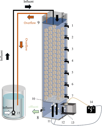 |
| | Fig. 1 1–8: sample port; 9: overflow port; 10: perforated partition; 11: cathode; 12: proton exchange membrane; 13: anode; 14: power supply; 15: pump. | |
The effluent was pumped into the reactor through a submersible pump. The overall flow pattern was arranged as the upper inlet and lower outlet. Specifically, the solution flowed into the reactor from the top, and an overflow port was set at the height of 800 mm to make the reactor filtered at a constant pressure. Seven sampling ports were set along the square column with the opening at the height of 750 mm, 650 mm, 550 mm, 450 mm, 350 mm, 250 mm, and 150 mm. The outlet was set at a height of 50 mm, with a rotor flowmeter arranged to control the water flow rate.
Experimental procedures
Experimental start-up. The synthetic wastewater was composed of NaNO3 (mg L−1), NaHCO3 (mg L−1), CHCOONa (mg L−1), and nutrient solution (mL L−1). The seed sludge was collected from Longwangzui Municipal Wastewater Treatment Plant (Wuhan, Hubei province, China). Firstly, DNBF-WE operated under the following conditions, including the influent nitrate concentration: 40 mg L−1, C/N: 3, HRT: 12 hours, I: 0 mA, and a sequential batch mode lasting 15 days. A yellow biofilm developed on the carrier indicated successful microbial inoculation. Subsequently, the focus shifted to microbial cultivation. The current incrementally increased from 0 mA to 100 mA, accompanied by a transition from sequential batch operation to continuous flow, and the HRT gradually decreased from 12 h to 3.5 h. The domestication process was successful when the nitrate removal rate exceeded 70%.
Experimental operation. The experiment was conducted under the optimal conditions, including C/N: 2, I: 60 mA, and HRT: 5 h. All experiments were conducted at room temperature and performed for at least one week under each condition to stabilize the nitrogen removal efficiency.
Analytical methods
Water quality index and calculation. Each water sample was filtered through a 0.45 μm membrane. NO3−–N, NO2−–N, and NH4+–N were determined using a spectrophotometer (model: UV-1100, HACH, Shanghai, China) according to the Chinese environmental standards HJ/T 346e-007 and GB 7493 × 1087, respectively.10 The chemical oxygen demand (COD) was determined by oxidation with potassium dichromate.The nitrate removal efficiency (NRE), volumetric denitrification rate (VDR), current utilization efficiency (CE) of DNBF-WE, and nitrate amount removed by COD (NO3−–N HD) can be calculated using the following formula:
| |
 | (1) |
| |
 | (2) |
| |
 | (3) |
| |
 | (4) |
where inf
CNO3− and eff
CNO3− represent the inlet and effluent nitrate concentrations (mg L
−1), respectively;
Q represents the filtration rate (m
3 d
−1);
I represents the applied electric current (mA);
n represents the electron transfer coefficient (
n = 1);
F represents the Faraday's constant (C mol
−1).
Eqn (3) is determined based on the electrolysis of water and Faraday's law of electrolysis. NO
3−–N
HD (mg L
−1) represents the amount of nitrates removed by HD. ΔCOD (mg L
−1) represents the difference in COD between the ports. 4 represents the electricity requirement per unit mole of oxygen consumed. 14 represents the molar mass fraction of N, and 32 represents the molar mass fraction of O
2. 5 represents the amount of electrons required to convert nitrates into nitrogen.
EPS extraction and determination. EPSs were extracted by a heating method. After the experiment, some PUFs were selected from each of the three zones. These PUFs were first washed with 0.1 M PBS buffer (pH 7.0), and bacteria were separated from PUFs by centrifugation (6000 rpm, 4 °C). The obtained cell pellet was resuspended with 40 mL of 0.05% NaCl solution, followed by a water bath at 60 °C for 30 min. The EPS solution was obtained by centrifugation at 10![[thin space (1/6-em)]](https://www.rsc.org/images/entities/char_2009.gif) 000 rpm for 15 min. The protein (PN) content was determined by anthrone–sulfuric acid colorimetry at 625 nm,11 and the content of polysaccharides (PS) was determined by the Bradford reagent coomassie brilliant blue colorimetric method at 595 nm.12
000 rpm for 15 min. The protein (PN) content was determined by anthrone–sulfuric acid colorimetry at 625 nm,11 and the content of polysaccharides (PS) was determined by the Bradford reagent coomassie brilliant blue colorimetric method at 595 nm.12
Microbial diversity analysis. Biofilm-enriched PUFs were collected from the top, middle, and bottom zones of DNBF-WE to analyze the microbial diversity. Sample 1 was collected from the carrier between the water surface and port 1 (top zone), sample 2 was collected from the PUFs between port 2 and port 4 (middle zone), and sample 3 was collected from the carrier between port 4 and port 7 (bottom zone), with triplicates collected from each port. The extracted DNA samples were subject to PCR amplification on bacterial 16S rDNA. Primers 338F (5′-ACTCCTACGGGGAGGCAGCA-3′) and 806R (5′-GGACTACHVGGGGTWTCTAAT-3 ′) were utilized for bacterial amplification. The structure of bacterial communities was determined using Illumina MiSeq high-throughput sequencing. The functional gene composition was inferred by comparing species composition information obtained from 16S sequencing data by PICRUSt2. Biofilm morphology in the three zones was qualitatively observed using scanning electron microscopy (SEM; JSM-IT300, Japan).
Results & discussion
Performance of DNBF-WE
The denitrification performance of DNBF-WE at the optimal conditions is shown in Fig. 2(a). Under the optimal conditions, the average eff NO3−–N was 8.26 mg L−1, the average eff NO2−–N was 0.96 mg L−1, the average NRE was 79.36%, the average VDR was 152.16 g N m−3 d−1, and the average effluent COD concentration was 9.55 mg L−1. The denitrification performance of DNBF-WE was compared with that in previous studies (Table 1). The VDR of DNBF-WE presented excellent performance compared with the conventional 3D-biofilm electrode reactor (3D-BER) and the sulfur autotrophic denitrification system. Besides, DNBF-WE overcame the disadvantages of the conventional biological system that required an excessively long HRT and a lower VDR.
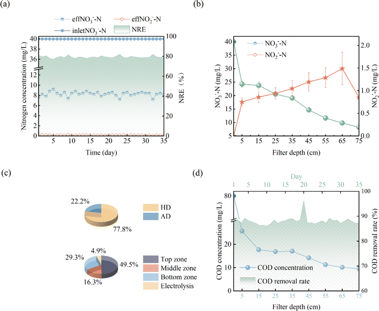 |
| | Fig. 2 Performance of DNBF-WE at C/N = 2, I = 60 mA, HRT = 5 h: nitrogen concentration and removal efficiency (a), variation of the nitrogen along vertical direction (b), the proportions of autotrophic and heterotrophic denitrification (c), contribution of nitrogen removal in different zones (d), variation of the COD concentration along vertical direction and COD removal rate with day. | |
Table 1 Comparison of VDR and NRE with previous denitrification systems
| Reactor type |
Denitrification type |
VDR (g N m−3 d−1) |
NRE (%) |
References |
| Electrolytic hydrogen reactor |
Hydrogen autotrophic |
1.58 |
81.60 |
6 |
| Multi-cathode BER |
Hydrogen autotrophic |
64.08 |
59.45 |
13 |
| CWS |
Sulfur autotrophic–heterotrophic |
2.78 |
81.71 |
14 |
| HEAD-PBR |
Hydrogen autotrophic–heterotrophic |
63.86 |
99.10 |
15 |
| DNBF-WE (C/N = 2, I = 60 mA, HRT = 5 h) |
Hydrogen autotrophic–heterotrophic |
152.16 |
75.46 |
This study |
| DNBF-WE (C/N = 2, I = 60 mA, HRT = 9.5 h) |
Hydrogen autotrophic–heterotrophic |
96.81 |
95.80 |
This study |
In this system, there were two electron donors for denitrification, namely the sodium acetate and hydrogen produced by electrolyzing water. Assuming that all COD was used for denitrification, the theoretical nitrate concentration removed by COD was calculated to be 24.67 mg L−1 according to eqn (4), and the nitrate concentration removed by hydrogen produced by electrolyzing water was 7.03 mg L−1. As shown in Fig. 2(c), the contribution of heterotrophic denitrification was 77.83%, and that of autotrophic denitrification and electrochemical action was 22.17%. Based on the above assumption, the theoretical CE calculated from eqn (3) can reach 78%.
Nitrogen conversion along the vertical direction of DNBF-WE
To further explore the conversion of elemental nitrogen in DNBF-WE, the nitrate concentration and the nitrite concentration were measured along the vertical direction of the filter, as shown in Fig. 2(b). In the top zone, the nitrate concentration decreased from 40 mg L to 24.29 mg L−1, and the nitrite concentration increased to 0.75 mg L−1, contributing 49.51% to DNBF-WE. With the vertical flow to the middle zone, the NO3−–N decreased to 19.11 mg L−1, and the NO2−–N increased to 1.05 mg L−1, contributing 16.29% to DNBF-WE. In the bottom zone, the nitrate concentration decreased to 9.83 mg L−1, and the nitrite concentration was 1.49 mg L−1, contributing 29.25% to DNBF-WE. Overall, the top zone had the highest denitrification rate, followed by the bottom zone, and the middle zone had the lowest denitrification rate. Heterotrophic denitrifying bacteria (HDB) grow faster than autotrophic denitrifying bacteria (ADB) under sufficient carbon sources.16 The sharp decrease in the nitrate concentration in the top zone was mainly attributed to the close distance from this zone to the inlet port. Specifically, the carbon source was relatively sufficient in the top zone, and abundant HDB could grow in this zone. Hence, heterotrophic denitrification could effectively remove nitrates, and the higher concentration of NO3−–N in the top zone promoted the higher abundance, diversity, and richness of denitrifying bacteria, which led to high denitrification efficiency.17,18 Besides, the organic electron donor was consumed in the top zone, and the available organic electron donor in the middle and bottom zones was not enough to support the removal of the rest nitrates. However, the ED below the bottom zone made hydrogen escape into the bottom zone. Hence, the nitrate removal rate and the contribution rate of nitrate removal in the bottom zone were higher than those in the middle zone. In the middle and bottom zones, nitrites gradually accumulated and nitrates were gradually removed as nitrite reductase was less competitive for electrons than nitrate reductase. In addition, denitrifying bacteria were more inclined to use nitrates as the terminal electron acceptors than nitrites in unstable environments, thus leading to nitrite accumulation. Of note, there were no carriers in the electrolysis department, but the nitrate concentration further decreased to 8.26 mg L and the nitrite concentration decreased to 0.85 mg L−1. It can be assumed that electrochemistry may contributed to the nitrogen loss in this zone. Electrochemical reactions (6) and (7) may occur in the electrolysis department.16 Although these reactions were side reactions of electrolysis for hydrogen production, they can reduce the current efficiency and also contribute to the removal of nitrates by DNBF-WE. Besides, there was a sufficient length for the biological reaction zone between the water surface and ED to avoid the direct escape of hydrogen. Therefore, the CE of DNBF-WE was high.| |
 | (5) |
| | |
NO−3 + H2O + 2e− ↔ NO−2 + 2OH−
| (6) |
| |
 | (7) |
As shown in Fig. 2(e), the COD concentration decreased sharply in the top zone. According to ΔCOD in the top zone, the removal amount of NO3−–N by HD in the top zone was 19.02 mg L−1 in theory, while the measured value was 14.71 mg L−1. COD slightly fluctuated in the middle zone. This result may be attributed to the flow of biofilms shed from the top zone into the middle zone, which may be decomposed and utilized by microorganisms. The theoretical removal amount of NO3−–N calculated by ΔCOD in the middle zone was 3.02 mg L−1, which was smaller than the measured value (5.17 mg L−1). In the bottom zone, the theoretical removal amount of NO3−–N by ΔCOD was 2.43 mg L−1, which was also lower than the measured value (9.29 mg L−1). Therefore, it could be speculated that there were hydrogen autotrophic denitrifying bacteria (HADB) in both the middle zone and the bottom zone, which used hydrogen to remove some nitrates. Hence, further microbial community evidence was required to verify whether HADB participated in nitrate removal.
Characteristics of EPSs along the vertical direction of DNBF-WE
As a category of complex mixtures, EPSs are secreted by microorganisms into the external environment. The composition of EPSs is similar to that of microbial intracellular components, mainly including proteins and polysaccharides. EPSs play an important role in the formation of biofilm, attachment, protection of microorganisms, and acquisition of nutrients.19 In this study, the EPSs extracted from sludge at different zones of DNBF-WE were analyzed, as shown in Fig. 3. It can be seen that both PS and PN decreased first and then increased with an increase in the depth of DNBF-WE. Specifically, the top zone had the highest concentration of EPSs (269.90 mg g−1 VSS), followed by the bottom zone (218.88 mg g−1 VSS), and the middle zone had the lowest concentration of EPSs (202.68 mg g−1 VSS). The high C/N was beneficial to the secretion of EPSs.20 The top zone, close to the water inlet, had the highest amount of organic matter, and it had the highest concentration of EPSs. The concentration of EPSs was almost similar in the middle zone and the bottom zone, but there was a significant difference compared with the top zone. Denitrifying bacteria could utilize PS and PN as electron donors for denitrification under a severe shortage of electron donors. Further, microorganisms could secrete more EPSs as an additional carbon source to cope with the gradually decreasing C/N under starvation conditions.21
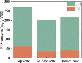 |
| | Fig. 3 The content of protein and polysaccharide of EPSs in different zones. | |
Since microorganisms can synthesize amino acids through multiple pathways, the content of PN was significantly higher than that of PS. However, there was only one pathway to generate polysaccharide precursors, and the relatively low content of TCA cycle intermediates under low carbon conditions led to a deficiency in substrates for PS biosynthesis. Different amino acids can be easily interconverted and many polysaccharide precursors were used for amino acid synthesis.22 The increase of PN was significantly larger than that of PS between different zones, indicating that PN, as the main component of EPSs in this experiment, effectively reflected the metabolism and activity of microorganisms.19 This explained why the strongest denitrification was observed in the top zone and the weakest one in the middle zone.
The morphology along the vertical direction of DNBF-WE
The biofilms of each zone were scanned using SEM to analyze their surface morphology (Fig. 4). The microorganisms in the three zones all grew as biofilms. Biofilms can protect the bacteria from harsh environmental conditions such as shear and limited nutrient availability.23 the predominant microbial morphology in each zone was rod-shaped, including bacilli with a predominant proportion. The disparity in the biofilm density among these zones was evident. Specifically, the top zone exhibited a higher density compared with both the middle zone and the bottom zone, as shown in Fig. 4a–f. This discrepancy could be attributed to the favourable presence of ample organic matter, which promoted the growth of microorganisms in the top zone. Similarly, the adequate supply of hydrogen in the bottom zone positively influenced microbial proliferation. Conversely, the middle zone experienced limited electron donors, consequently suppressing the growth of microorganisms.
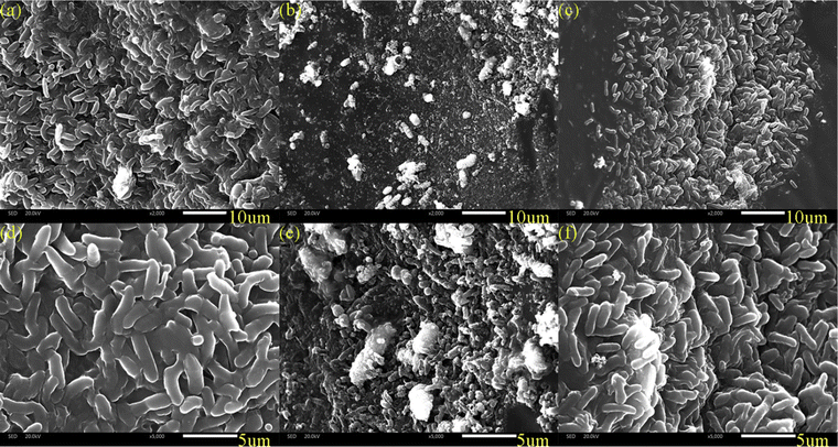 |
| | Fig. 4 SEM images of different zones in DNBF-WE: (a and d) the top zone; (b and e) the middle zone; (c and f) the bottom zone. | |
Microbial community and structure along the vertical direction of DNBF-WE
Microbial community and structure shift along the vertical direction of EN-DNBF. The microbial community and structure of the samples were analyzed by Illumina high-throughput sequencing of the 16S rRNA gene. The species richness indices and diversity indices for samples from three distinct zones are presented in Table 2. There were significant differences in the richness and diversity of microbial communities among these different zones. The Chao 1 and ACE indexes were positively correlated with microbial richness. The top zone had the highest species richness, followed by the bottom zone and the middle zone. The reason was that most microbial communities in the top zone were composed of HDB, which were less ecologically sensitive and were not easily affected by environments (nutritional conditions).24 The Shannon and Simpson indexes were correlated with microbial diversity. More specifically, a higher Shannon index represented richer diversity, and the Simpson index was on the contrary. It was obvious that the microbial diversity of these three zones gradually decreased, which indicated the gradual simplification of microbial structures and the enrichment of advantageous bacteria.
Table 2 The richness and diversity indexes of samples from DNBF-WE
| Groups |
Chao 1 |
Shannon |
Simpson |
ACE |
| Top zone |
139.5 |
3.09 |
0.228 |
152.531 |
| Middle zone |
130.8 |
2.35 |
0.368 |
138.8451 |
| Bottom zone |
132.0 |
1.59 |
0.596 |
150.8098 |
Changes in the structure of denitrifying bacterial communities and the composition of microorganisms may affect the denitrification rate.25 The composition of microorganisms at the phylum level in the three zones is shown in Fig. 5a–c. Proteobacteria constituted the dominant species in all three zones, and the abundance of Proteobacteria in the bottom zone (94.4%) was higher thanthat in the top zone (73.4%) and the middle zone (84.7%). Proteobacteria played a crucial role in denitrification, and the increased enrichment of Proteobacteria was a direct response to enhanced denitrification.26 In addition, Bacteroidetes (20.6%), Acidobacteria (2.7%), and Chloroflexi (1.2%) were enriched in the top zone; Bacteroidetes (9.9%), and Nitrospirae (2%) were enriched in the middle zone; Chloroflexi (1.1%), Bacteroidetes (2.1%), and Nitrospirae (1.6%) were enriched in the bottom zone. This result suggested that the abundance of Proteobacteria increased and the microbial community diversity decreased along the vertical direction of DNBF-WE, allowing denitrifying bacteria to be enriched and domesticated.
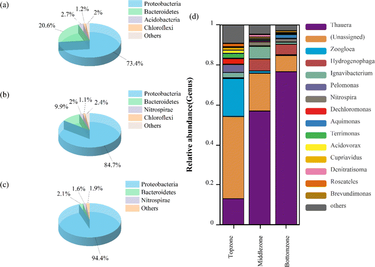 |
| | Fig. 5 Microbial community structure of three zones: at the phylum level (a–c), at the genus levels (d). | |
Fig. 5(d) shows the significant variability of microbial communities at the genus level in the three zones. The dominant genera in the top zone included Zoogloea (18.91%), Thauera (12.95%), and some miscellaneous bacteria. The dominant genera in the middle zone included Thauera (56.86%), Ignavibacterium (6.24%), and Hydrogenophaga (6.03%). The dominant genera in the bottom zone included Thauera (76.55%) and Hydrogenophaga (5.23%). The abundance of Thauera and Hydrogenophaga gradually increased along the vertical direction of DNBF-WE. Thauera can utilize organic matter as a carbon source for heterotrophic denitrification as well as H2 as an electron donor for hydrogen autotrophic denitrification. Besides, Thauera can use EPS as an electron donor for denitrification, and it seemed to be ecologically superior to its competitors in terms of the low-carbon domestic wastewater treatment system.27 Thauera might contain specialized autotrophic denitrifying bacteria, which played a dominant role in hydrogen autotrophic denitrification.28 Hydrogenophaga was a predominantly parthenogenetic hydrogenotrophic denitrifying bacterium that can promote hydrogen autotrophic denitrification in the absence of organic matter.29 This suggested that hydrogen produced by electrolyzing water promoted the enrichment of Thauera and Hydrogenophaga. Thus, hydrogen autotrophic heterotrophic synergistic denitrification was achieved in this study. Thauera achieved partial denitrification under the presence of insufficient electron donors, thereby leading to nitrite accumulation. However, nitrites decreased under sufficient electron donors.30 As an aerobic denitrifying bacterium, Zoogloea was rapidly selected in the presence of organic matter and terminal electron acceptors (such as dissolved oxygen).31 Zoogloea can produce numerous EPSs, which contributed to its accumulation to form biofilms, thus improving denitrification performance.32 Ignavibacterium was highly enriched in the middle zone. It was reported that Ignavibacterium can degrade complex organic substances,33 and Dechloromonas can convert external carbon sources into EPSs and store them in cells.34 This explained the high abundance of Dechloromonas and abundant EPSs in the top zone.
Functional prediction of microbial communities along the vertical direction of DNBF-WE
To date, many researchers have reported the function of microorganisms throughout the system. However, the spatial heterogeneity of functional communities and the relationship between various zones are neglected. In this study, to explore the difference in community functions between different zones of DNBF-WE at the genomic level, high-level cell functions were predicted based on the KEGG catalog. The relative abundance of enzymes and functional genes involved in the nitrogen cycle was predicted based on PISCRUST2,35 as shown in Fig. 6. The main metabolic pathways of nitrogen included nitrogen fixation, ammonia oxidation, dissimilatory nitrate reduction, assimilatory nitrate reduction, and denitrification. As the key enzymes for nitrite removal, nitrite-reductase (EC1.7.2.1, nitrite–nitric oxide) and nitrite-reductase (EC1.7.1.15, nitrite–ammonia) showed the opposite trend. Specifically, the abundance of EC1.7.1.15 gradually decreased with an increase in the filter depth, but that of EC1.7.2.1 gradually increased with an increase in the filter depth. This indicated that denitrification became more dominant than dissimilatory nitrate reduction. As the key genes for denitrification, narGHI and napAB (NO3− → NO2−) had the highest total relative abundance in the middle zone, followed by the bottom zone, and the lowest in the top zone. The limited nutritional conditions and nitrate stress up-regulated the expression of functional genes. The same phenomenon was reported in a previous study.36 However, the lowest expression level of nirKS (NO2− → NO) was observed in the top zone, followed by the middle zone. It induced competition among dissimilatory nitrate reduction, assimilatory nitrate reduction, and denitrification for substrates. Besides, the dissimilatory nitrite reduction was more advantageous than denitrification in the top zone under sufficient nutrients.37 Nitrites can be catalyzed by anabolic nitrite reductase to ammonia. Finally, the ammonia was absorbed through the glutamate cycle for microbial growth,38,39 resulting in a higher density of biofilms and EPSs in the top zone. The highest expression level of NirKS (NO2− → NO) and norBC (NO → NO2) was observed in the bottom zone, followed by the middle zone, and the lowest in the top zone. This phenomenon was consistent with nitrite accumulation. The abundance of nosZ (NO2 → N2) was highest in the top zone and lowest in the middle zone, which was consistent with the nitrogen removal performance. The higher abundance of nosZ indicated a more complete denitrification process in the top zone than in other zones, which highlighted its importance.40
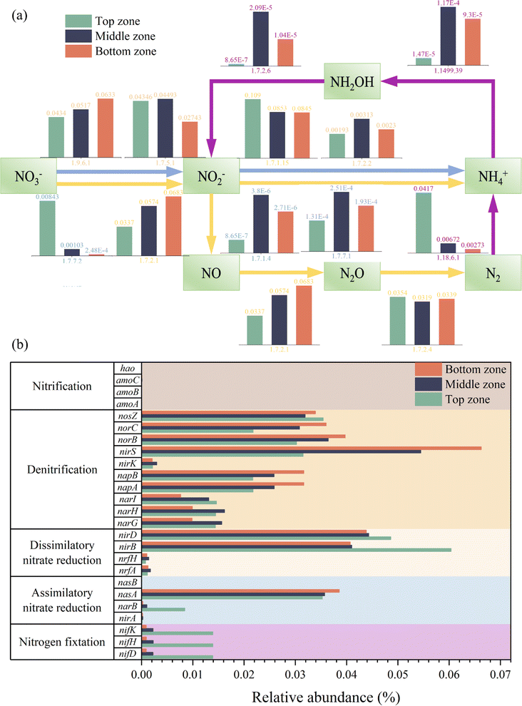 |
| | Fig. 6 Relative abundance of the key enzyme (a) and functional genes (b) in the nitrogen metabolism pathway in different zones of DNBF-WE based on KEGG (map 00910). | |
Key roles of denitrification along the vertical direction of DNBF-WE
In this study, the top zone was responsible for main nitrate removal by utilizing organic matter, where a large proportion of typical HDB (Zoogloea, Ignavibacterium, and Dechloromonas) accumulated. HDB consumed a large proportion of the organic carbon source and secreted many EPSs. Besides, the gene related to dissimilatory nitrate reduction (nirBD) was highly expressed, which produced NH4+–N, and finally, NH4+–N was absorbed through the glutamate cycle for microbial growth (Fig. 7). Although the contribution of nitrate removal was 49.5% in the top zone, a considerable portion of nitrogen pollutants remained for nutrition stress. As a transition region, the middle zone can utilize residual organic matter and microbial tissues by biodegradation (Ignavibacterium), as well as partially spilled hydrogen from the bottom zone by HADB (Thauera and Hydrogenophaga). Hence, the middle zone had a limited removal capacity, which led to the accumulation of denitrification intermediates. The bottom zone was responsible for residual nitrogen pollution from upper zones by HADB (Thauera and Hydrogenophaga) using hydrogen from ED, and the genes related to intermediate removal (nirKS and norBC) had a high expression level. ED can remove nitrogenous compounds through electrochemistry. Overall, the interaction among heterotrophic denitrification, hydrogen autotrophic denitrification and electrochemistry gave a strong support to DNBF-WE.
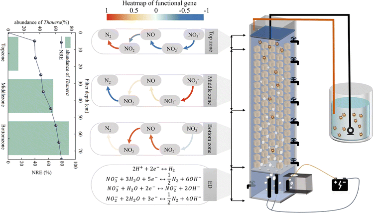 |
| | Fig. 7 Vertical spatial denitrification performance and microbial community of the denitrification biofilter coupled with water electrolysis. | |
Conclusions
The downward flow of DNBF-WE with the polyurethane sponge as the filter medium was effective in treating nitrate pollution in the secondary effluent of wastewater disposal plants. The NRE of DNBF-WE reached 79.36%, CE reached 78%, and VDR reached 152.16 g N m−3 d−1 under C/N = 2, I = 60 mA, and HRT = 5 h. The denitrification performance of DNBF-WE varied in different zones. Specifically, the top zone contributed almost half of nitrate removal, and the middle and bottom zones contributed 16.29% and 29.25% of nitrate removal, respectively. The reactor participated in denitrification, with Thauera as the dominant genus on different vertical zones. The abundance of Thauera increased from 12.95% to 76.55% from top to bottom. Thauera can utilize not only organic matter but also H2 as electron donors for the denitrification process. This community difference contributed to enhancing the denitrification capacity and achieving stable performance. The genes related to nitrogen removal exhibited different expression levels in these three zones. Moreover, the nitrogen removal rate also varied in different zones. Despite these differences, these components formed a synergistic mechanism, thus realizing efficient nitrate removal.
Conflicts of interest
There are no conflicts to declare.
Acknowledgements
This work was funded by the National Natural Science Foundation of China (No. 21806126) and the Fundamental Research Funds for the Central Universities (WUT.2019IVB031).
Notes and references
- Q. Zhou, H. Sun, L. Jia, W. Wu and J. Wang, Chemosphere, 2022, 296, 134054 CrossRef CAS PubMed.
- Y. X. Cui, G. Guo, G. A. Ekama, Y. F. Deng, H. K. Chui, G. H. Chen and D. Wu, Water Res., 2019, 162, 246–257 CrossRef CAS PubMed.
- T. Ai, H. Zhan, L. Zou, J. Fu, Q. Fu, Q. He and H. Ai, Sci. Total Environ., 2020, 722, 137830 CrossRef CAS PubMed.
- F. Di Capua, S. Papirio, P. N. L. Lens and G. Esposito, Chem. Eng. J., 2015, 280, 643–657 CrossRef CAS.
- Y. Sakakibara, H. Cong Vo, K. Naito, A. Kiga and J. Ye, Water Supply, 2015, 15, 881–888 CrossRef.
- Y. Inagaki, D. Yamada, M. Komori and Y. Sakakibara, J. Water Proc. Eng., 2020, 38, 101685 CrossRef.
- P. Li, W. Xing, J. Zuo, L. Tang, Y. Wang and J. Lin, Bioresour. Technol., 2013, 144, 452–459 CrossRef CAS PubMed.
- Y. García-Martínez, J. Chirinos, C. Bengoa, F. Stüber, J. Font, A. Fortuny and A. Fabregat, Chem. Eng. Process., 2017, 121, 57–64 CrossRef.
- X. Xue, Z. Liu, W. Cai, K. Cui and K. Guo, Bioresour. Technol. Rep., 2022, 18, 101073 CrossRef CAS.
- Y. Zhang, G. B. Douglas, A. H. Kaksonen, L. Cui and Z. Ye, Sci. Total Environ., 2019, 646, 1195–1203 CrossRef CAS PubMed.
- F. A. Loewus, Anal. Chem., 1952, 24, 219 CrossRef CAS.
- M. M. Bradford, Anal. Biochem., 1976, 72, 248–254 CrossRef CAS PubMed.
- Y. Sakakibara and T. Nakayama, Water Res., 2001, 35, 768–778 CrossRef CAS PubMed.
- H.-c. Wang, Y. Liu, Y.-m. Yang, Y.-k. Fang, S. Luo, H.-y. Cheng and A.-j. Wang, Water Res., 2022, 226, 119258 CrossRef CAS PubMed.
- T. Peng, C. Feng, W. Hu, N. Chen, Q. He, S. Dong, Y. Xu, Y. Gao and M. Li, Biochem. Eng. J., 2018, 134, 12–21 CrossRef CAS.
- A. Vijay, M. Chhabra and T. Vincent, Bioresour. Technol., 2019, 272, 217–225 CrossRef CAS PubMed.
- X. Huang, C. Duan, J. Yu and W. Dong, Bioresour. Technol., 2022, 345, 126471 CrossRef CAS PubMed.
- H. Song, J. Feng, L. Zhang, H. Yin, L. Pan, L. Li, C. Fan and Z. Wang, Environ. Technol. Innovat., 2021, 24, 102044 CrossRef CAS.
- S. Zheng, X. Liu, X. Yang, H. Zhou, J. Fang, S. Gong, J. Yang, J. Chen, T. Lu, M. Zeng and Y. Qin, Bioresour. Technol., 2022, 363, 127901 CrossRef CAS PubMed.
- A. P. Miqueleto, C. C. Dolosic, E. Pozzi, E. Foresti and M. Zaiat, Bioresour. Technol., 2010, 101, 1324–1330 CrossRef CAS PubMed.
- Z.-T. Feng, X. Ma, Y.-J. Sun, J.-M. Zhou, Z.-G. Liao, Z.-C. He, F. Ding and Q.-Q. Zhang, Bioresour. Technol., 2023, 386, 129566 CrossRef CAS PubMed.
- C. Ma, W. Zeng, Q. Meng, C. Wang and Y. Peng, Chemosphere, 2022, 286, 131895 CrossRef CAS PubMed.
- P. K. Taylor, A. T. Y. Yeung and R. E. W. Hancock, J. Biotechnol., 2014, 191, 121–130 CrossRef CAS PubMed.
- S. Sun, H. Lei and S. X. Chang, Biol. Fertil. Soils, 2019, 55, 275–283 CrossRef CAS.
- J. Kjellin, S. Hallin and A. Wörman, Water Res., 2007, 41, 4710–4720 CrossRef CAS PubMed.
- L. Huang, J. Ye, H. Xiang, J. Jiang, Y. Wang and Y. Li, Bioresour. Technol., 2020, 300, 122658 CrossRef CAS PubMed.
- T. Ren, Y. Chi, Y. Wang, X. Shi, X. Jin and P. Jin, Water Res., 2021, 206, 117742 CrossRef CAS PubMed.
- Y. Mao, Y. Xia and T. Zhang, Bioresour. Technol., 2013, 128, 703–710 CrossRef CAS PubMed.
- J. Liessens, J. Vanbrabant, P. De Vos, K. Kersters and W. Verstraete, Microb. Ecol., 1992, 24, 271–290 CrossRef CAS PubMed.
- Z. Hou, W. Dong, H. Wang, Z. Zhao, Z. Li, H. Liu, Y. Li, Z. Zeng, J. Xie, L. Zhang and J. Liu, Bioresour. Technol., 2023, 384, 129269 CrossRef CAS PubMed.
- B. Guo, N. Yu, D. G. Weissbrodt and Y. Liu, Water Res., 2021, 196, 117035 CrossRef CAS PubMed.
- D. Liang, W. He, C. Li, F. Wang, J. C. Crittenden and Y. Feng, Water Res., 2021, 188, 116498 CrossRef CAS PubMed.
- Z. Liu, N. U. Frigaard, K. Vogl, T. Iino, M. Ohkuma, J. Overmann and D. A. Bryant, Front. Microbiol., 2012, 3, 185 Search PubMed.
- J. Fan, R. Du, Q. Liu, C. Li and Y. Peng, Chem. Eng. J., 2024, 481, 148404 CrossRef CAS.
- M. G. I. Langille, J. Zaneveld, J. G. Caporaso, D. McDonald, D. Knights, J. A. Reyes, J. C. Clemente, D. E. Burkepile, R. L. Vega Thurber, R. Knight, R. G. Beiko and C. Huttenhower, Nat. Biotechnol., 2013, 31, 814–821 CrossRef CAS PubMed.
- Z. Wang, J. Su, R. Zhang, K. Li, R. Hu, Y. Liu, L. Zhang and J. Li, Bioresour. Technol., 2022, 364, 128098 CrossRef CAS PubMed.
- C. B. Pandey, U. Kumar, M. Kaviraj, K. J. Minick, A. K. Mishra and J. S. Singh, Sci. Total Environ., 2020, 738, 139710 CrossRef CAS PubMed.
- Y. Han, Y. Feng, N. Wang, P. Yang, G. Ding, J. An, J. Liu, N. Li and W. He, J. Clean. Prod., 2023, 414, 137627 CrossRef CAS.
- Y. Lu, X. Li, Y. Chen, Y. Wang, G. Zhu and R. J. Zeng, Sci. Total Environ., 2020, 746, 141089 CrossRef CAS PubMed.
- Y. Liu, X. Liu, K. Li, S. Lu, X. Guo, J. Zhang and B. Xi, Sci. Total Environ., 2019, 652, 977–988 CrossRef PubMed.
|
| This journal is © The Royal Society of Chemistry 2024 |
Click here to see how this site uses Cookies. View our privacy policy here.  Open Access Article
 *,
Yu Huang,
Shenyu Tan and
Heng Yang


![[thin space (1/6-em)]](https://www.rsc.org/images/entities/char_2009.gif) 000 rpm for 15 min. The protein (PN) content was determined by anthrone–sulfuric acid colorimetry at 625 nm,11 and the content of polysaccharides (PS) was determined by the Bradford reagent coomassie brilliant blue colorimetric method at 595 nm.12
000 rpm for 15 min. The protein (PN) content was determined by anthrone–sulfuric acid colorimetry at 625 nm,11 and the content of polysaccharides (PS) was determined by the Bradford reagent coomassie brilliant blue colorimetric method at 595 nm.12


