
 Open Access Article
 This Open Access Article is licensed under a Creative Commons Attribution-Non Commercial 3.0 Unported Licence
Catalytic effects of graphene structures on Pt/graphene catalysts†
Zhenzhen Du ab,
Fan Yub,
Jun Wangab,
Jiongli Liab,
Xudong Wang*ab and
Aniu Qian*c
ab,
Fan Yub,
Jun Wangab,
Jiongli Liab,
Xudong Wang*ab and
Aniu Qian*c
aAECC Beijing Institute of Aeronautical Materials, Beijing 100095, China. E-mail: netfacn@163.com
bBeijing Institute of Graphene Technology, Beijing 100094, China
cInstitute of Resources and Environment Engineering, Shanxi University, Taiyuan 030006, China. E-mail: anqian@sxu.edu.cn
First published on 16th July 2024
Abstract
Pt/C catalysts have been considered the ideal cathodic catalyst for proton exchange membrane fuel cells (PEMFCs) due to their superior oxygen reduction reaction (ORR) catalytic activity at low temperatures. However, oxidation and corrosion of the carbon black support at the cathode result in the agglomeration of Pt particles, which reduces the active sites in the Pt/C catalyst. Graphene supports have shown great promise to address this issue, and therefore, finding out the main structural features of the graphene support is of great significance for guiding the rational construction of graphene-based Pt (Pt/graphene) catalysts for optimized ORR catalysts. In order to systematically study the influence of the structural features of the graphene support on the electro-catalytic properties of Pt/graphene catalysts, we prepared porous nitrogen-doped reduced graphene oxide (P-NRGO), nitrogen-doped reduced graphene oxide (NRGO), treated P-NRGO (TP-NRGO) and reduced graphene oxide (RGO) with different nitrogen species contents (7.76, 7.54, 3.24, and 0.14 at%), oxygen species contents (18.68, 18.12, 6.34 and 21.12 at%), specific surface areas (370.4, 70.6, 347.7 and 276.2 m2 g−1) and pore volumes (1.366, 0.1424, 1.3299 and 1.0414 cm3 g−1). The ORR activity of the four Pt/graphene catalysts when listed in the order of their half-wave potentials (E1/2) and peak power densities was found to be as Pt/P-NRGO > Pt/NRGO > Pt/TP-NRGO > Pt/RGO. The long-term durability of Pt/P-NRGO for the operation of H2–air PEMFCs is better than that of commercial Pt/C catalysts. The excellent ORR catalytic performance of Pt/P-NRGO compared to that of the other three Pt/graphene catalysts is ascribed to the high nitrogen species content of P-NRGO that can facilitate the uniform dispersion of Pt particles and provide accessible active sites for ORR. The results indicate that the specific surface area (SSA) and heteroatom dopants have strong influence on the Pt particle size, and that the nitrogen species of graphene supports play a more important role than the oxygen species, specific surface area and pore volume for the Pt/graphene catalysts in providing accessible active sites.
1. Introduction
Proton exchange membrane fuel cells (PEMFCs) have attracted considerable attention because they can convert chemical energy into electrical energy without causing pollution.1–3 It is known that platinum (Pt) has been considered the ideal cathodic catalyst due to its superior ORR catalytic activity at low temperatures.4,5 Support materials play an important role in determining the electro-catalytic performance, durability and efficiency of cathodic catalysts, particularly for the diffusion of reactants and the transport of products.6 The support material not only anchors and disperses Pt particles but also contributes to catalytic activity and durability.4,7 The support material properties including high electrical conductivity, moderate catalyst–support interaction, large specific surface area (SSA) and excellent corrosion resistance are the keys to optimized cathodic catalysts.8Carbon black materials are commonly used as the support material to accommodate Pt particles to provide diffusion channels for mass transport and charge transfer in ORRs.9 However, the carbon black support suffers from oxidation and corrosion at the cathode in a harsh electrochemical environment, which causes Pt particles to fall off from the carbon black support, resulting in the agglomeration of Pt particles.10,11 Furthermore, the agglomeration leads to a reduction of the active sites in the Pt/C catalyst, thus reducing the activity and stability of the Pt/C catalyst.12,13 Therefore, it is necessary to find a more stable support material to improve the catalytic activity of the catalyst. The use of graphitized nano carbon is an effective way to solve the above-mentioned oxidation and corrosion resistance problems, thus improving the performance and stability of the catalyst.14–18
Graphene is a sp2-hybridized carbon with high graphitization, and exhibits high electrical conductivity, high surface area, and excellent mechanical strength.19,20 Therefore, it is a promising material used as the support material of cathodic catalysts. However, a major issue with the graphene support is its “stacking” through π–π interaction, particularly when graphene-supported materials are dried.21–23 The stacking results in an agglomerate structure, which blocks the mass transport of reactive species, and thus, retards the catalytic reaction. Various efforts have been devoted to the construction of porous graphene structures to prevent the graphene sheets from agglomeration.24–26 The cross-linked porous network that is usually accompanied by high SSA shortens the diffusion distance from the reactants to the catalytically active sites during the ORR, thereby exhibiting a high catalytic performance.26 Furthermore, highly graphitized graphene has a weak interaction with Pt particles, which is unsatisfactory to deposit well-dispersed, uniform-sized nanoparticles.27–29 Pioneering studies have focused on introducing heteroatom dopants (i.e., nitrogen,30–32 oxygen,22,33 sulfur,34–36 and phosphorus37,38) or organic cations27 into the graphene structures to tailor the graphene–Pt interaction.
The structural features of graphene supports including morphology (SSA and pore volume) and surface chemistry play an important role in obtaining optimized graphene-based Pt (Pt/graphene) catalysts. The morphology and electro-catalytic property of the Pt/graphene catalyst depend on a complex synergy between the morphology and the surface chemistry of graphene supports, yet the major factors should be present. Finding out the main structural features of the graphene support is of great significance for guiding the rational construction of the graphene-based Pt material for optimized ORR catalysts.
In this study, we synthetized four types of graphene materials. The porous nitrogen-doped reduced graphene oxide (P-NRGO) material has a high concentration of nitrogen species of 7.76 at%, a moderate concentration of oxygen species of 18.68 at% and a high SSA of 370.4 m2 g−1 with an average pore volume of 1.366 cm3 g−1. The nitrogen-doped reduced graphene oxide (NRGO) material has a high concentration of nitrogen species of 7.54 at%, a concentration of oxygen species of 18.12 at% similar to that of P-NRGO, the lowest SSA of 70.6 m2 g−1 and the lowest average pore volume of 0.1424 cm3 g−1. The treated P-NRGO (TP-NRGO) material has a low concentration of nitrogen species of 3.24 at%, a concentration of oxygen species of 6.34 at%, an SSA of 347.7 m2 g−1 and an average pore volume of 1.3299 cm3 g−1. The reduced graphene oxide (RGO) material has the lowest concentration of nitrogen species of 0.14 at%, the highest concentration of oxygen species of 21.12 at%, an SSA of 276.2 m2 g−1 and an average pore volume of 1.0414 cm3 g−1. Pt particles were impregnated in the P-NRGO, NRGO, TP-NRGO and RGO materials to obtain Pt/graphene catalysts with a Pt content of around 40 wt%. The ORR catalytic activity of the four Pt/graphene catalysts reaches Pt/P-NRGO > Pt/NRGO > Pt/TP-NRGO > Pt/RGO when listed in the order of their half-wave potentials (E1/2) and peak power density. The long-term durability of Pt/P-NRGO for the operation of H2–air PEMFCs is better than that of commercial Pt/C catalysts. The excellent ORR catalytic performance of Pt/P-NRGO compared to the other three Pt/graphene catalysts is ascribed to the high nitrogen species content of P-NRGO that can facilitate the uniform dispersion of Pt particles and provide accessible active sites for the ORR. The results indicate that the SSA and heteroatom dopants have strong influence on the size of Pt particles, and that the nitrogen species of graphene supports play a more important role than the oxygen species, SSA and pore volume for the Pt/graphene catalysts in providing accessible active sites.
2. Experimental section
2.1. Preparation of graphene materials
A GO (graphene oxide) slurry was prepared by the modified Hummers' method.39 A spherical GO powder was obtained after spray drying of the GO slurry at 50 °C. For the synthesis of P-NRGO, 3 g of spherical GO powder and 80 ml of ammonium hydroxide were placed into a zirconia jar containing stainless steel balls (200 g, diameter 3 mm), and then, the jar was fixed in a planetary ball grinder and agitated at 200 rpm for 5 h to obtain a nitrogen-doped GO (NGO) suspension. The NGO powder was collected via five cycles of filtration-rinse, followed by a freeze-drying technique. Finally, porous nitrogen-doped reduction graphene oxide (P-NRGO) was obtained by heating the NGO powder at 750 °C under an Ar atmosphere for 30 minutes with a temperature ramp of 50 °C min−1. Nitrogen-doped reduction graphene oxide (NRGO) was prepared following the same procedure as those for P-NRGO except for the use of a temperature ramp of 10 °C min−1 for heating. Treated porous nitrogen-doped reduced graphene oxide (TP-NRGO) with a low nitrogen content was prepared following the same procedure as those for P-NRGO except that the heating time was 2.5 hours. For the preparation of reduced graphene oxide (RGO), GO was heated under an Ar atmosphere at 750 °C for 30 minutes with a temperature ramp of 10 °C min−1.2.2. Preparation of Pt/graphene catalysts
Pt/graphene catalysts were prepared by a glycol reduction process. In detail, 120 mg of graphene powders were dispersed in ethylene glycol by ultrasonication for 2 hours to obtain a graphene solution with a concentration of 1 mg ml−1. Then 220 ml of chloroplatinic acid solution (0.25 mg ml−1 Pt in ethylene glycol) was added to the graphene solution, and the mixture was kept under stirring for 40 minutes. Thereafter, the above-mentioned solution was stirred at 130 °C for 5 hours under the reflux conditions. The Pt/graphene catalysts were obtained by filtration and finally dried by a freeze-drying technique.2.3. Characterization
Scanning electron microscopic (SEM) observation was performed using a JSM-7610F (JEO Ltd). Transmission electron microscopic (TEM) observation was performed using a JEM-ARM200F (JEOL Ltd) at an accelerating voltage of 200 kV. Atomic force microscopy (AFM) was performed using a Bruker Dimension FastScan in the tapping mode. Raman spectra were recorded using a HORIBA Scientific LabRAM HR Evolution under 532 nm incident laser excitation. X-ray photoelectron spectroscopy (XPS) analysis was performed using a Thermo Fisher Scientific, 250Xi instrument. Nitrogen adsorption/desorption isotherms were performed using an ASAP 2460 to determine the specific surface areas (SSAs) and pore volumes of the graphene materials. The SSAs were obtained by the Brunauer–Emmett–Teller (BET) analysis and the pore volumes were determined by the BJH model. Thermogravimetric analysis (TGA, NETZSCH STA 449 F3/F5) was performed in an air atmosphere at a heating rate of 5 °C min−1 to 800 °C to calculate the Pt contents in the Pt/graphene catalysts. X-ray diffraction (XRD) measurements were conducted using a Bruker D8-Advance X-ray diffractometer (Cu Kα radiation, λ = 1.5406 Å).2.4. Electrochemical measurements
Electrochemical characterizations of Pt/graphene catalysts were performed using a CHI 760E electrochemical workstation connected by a three-electrode system. First, 4 mg of graphene catalysts and 50 μl of 5 wt% Nafion were dispersed in 2 ml of ethanol by ultrasonication for 30 min to obtain a catalyst ink. Then 8 μl of this catalyst ink was drop-casted onto a glassy carbon electrode (Pine Instrumentation) with an electrode area of 0.196 cm2 and dried at room temperature. Cyclic voltammetry (CV) curves were measured in a N2-saturated 0.5 M H2SO4 electrolyte in the range of 0.0–1.2 V vs. RHE at a scan rate of 50 mV s−1. The electrochemical surface area (ECSA) of Pt nanoparticles was obtained by calculating the integral area of the hydrogen desorption region in the CV curve. The ORR properties were obtained in an O2-saturated 0.5 M H2SO4 electrolyte in the range of 0.0–1.0 V vs. RHE at a scan rate of 10 mV s−1 and a speed of 1600 rpm. The hydrogen peroxide (H2O2) yield (H2O2%) and the corresponding number of transferred electrons (n) were determined using the following eqn (1) and (2):
 | (1) |
 | (2) |
The Pt/graphene and Pt/C catalysts were investigated as cathode catalyst layers in the membrane electrolyte assembly (MEA) testing. For this, 1 mg ml−1 of catalyst inks were made by mixing a certain amount of catalysts with 5 wt% Nafion solution and isopropyl alcohol, followed by sonication of the dispersion solution at room temperature for 1 h. The I/C ratio of the catalyst inks was 0.4. The catalyst inks were then spray-coated onto the DMR100 Nafion membrane using an UC330 ultrasonic spraying system to obtain the a catalyst-coated membrane (CCM). The Pt loading was 0.1 mg cm−2 and 0.2 mg cm−2 for the anode and cathode, respectively. Two pieces of 40 μm PTFE films were placed on both sides of the CCM and pressed at 120 °C under the protection of a heat-resistant packaging mold. Then, the film was cooled to room temperature. The carbon paper which includes a microporous layer (total thickness of 235 mm) was used as the gas diffusion layer (GDL). Finally, two pieces of GDLs were placed on both sides of the cathode and anode and fixed with the fuel cell adhesive to obtain the MEA. The active area of the MEA was 5 × 5 cm2. The single H2–air cell performances of catalysts were tested using an RG11100 fuel cell test system. The MEA was sandwiched between two graphite plates with serpentine flow channels machined in them. H2/air was fed into the anode/cathode with a stoichiometry ratio of 1.2/2.5. During the measurements, the MEA was maintained at 75 °C, 150 kPaabs (abs: absolute) and 100% RH. In order to test the practical durability of catalysts in the MEA, an accelerated durability test (ADT) was performed. According to the DOE MEA ADT protocol, a square wave voltage ranging from 0.6 to 0.95 V with a duration of 3 s at each voltage was applied on the MEA for 30![[thin space (1/6-em)]](https://www.rsc.org/images/entities/char_2009.gif) 000 cycles. Each ADT was operated at 75 °C, 150 kPaabs (abs: absolute), and 100% RH, at a H2/N2 flow rate of 0.5/0.5 slpm for the anode and cathode, respectively.
000 cycles. Each ADT was operated at 75 °C, 150 kPaabs (abs: absolute), and 100% RH, at a H2/N2 flow rate of 0.5/0.5 slpm for the anode and cathode, respectively.
3. Results and discussion
3.1. Structural characterization
The P-NRGO, NRGO, TP-NRGO and RGO materials were synthesized by the method described in the experimental section. The morphologies of the four graphene samples were examined by SEM. As shown in Fig. 1a–d, the P-NRGO and TP-NRGO materials have the similar interconnected 3D frameworks, while NRGO aggregates owing to the strong van der Waals forces among individual graphene nanosheets. In the RGO material, the graphene nanosheets are stacked into porous ball structures. It is worth noting that although the treatment temperature for preparing P-NRGO and NRGO is the same, the morphology of P-NRGO is different from that of NRGO. The reason for this difference is that the ramping temperature rate for preparing P-NRGO (50 °C min−1) is much higher than that for preparing NRGO (10 °C min−1). Compared with slow heating, rapid heating makes NGO obtain high energy instantly and achieve rapid reduction, accompanied by the release of a large amount of gas, which contributes to forming a porous structure.40 Furthermore, although the ramping temperature rate and treatment temperature for the preparation of NRGO and RGO are the same, their morphologies are completely different. The raw materials required for achieving thermal reduction in the preparation of NRGO and RGO are dense NGO blocks (Fig. S1†) and spherical GO (Fig. S2†), respectively. The size of spherical GO is much smaller than that of massive NGO. During the thermal reduction of small-sized spherical GO, the slowly released gas partially pushes apart the graphene sheet and forms porous ball structures. However, it is difficult for massive NGO to expand into porous structures at a slow heating rate owing to the strong van der Waals forces among individual graphene nanosheets, and hence, NRGO retains the NGO stack structure.41 AFM images (Fig. S3†) show that the thickness of GO and the four graphene materials is about 2.85–3.32 nm. Since the thickness of a single graphene sheet is about 0.34 nm,42 the number of graphene layers for GO and the four graphene materials is about 8–10 layers. The N2 adsorption/desorption isotherms were performed to determine the SSAs and the pore volumes of the four graphene samples (Fig. 1e and f). The P-NRGO and TP-NRGO have similar SSAs of 370.4 and 347.7 m2 g−1, respectively, which are significantly higher than those of the NRGO (70.6 m2 g−1) and RGO (276.2 m2 g−1) materials. The pore volumes of the P-NRGO, NRGO, TP-NRGO and RGO materials are 1.366, 0.1424, 1.3299 and 1.0414 cm3 g−1, respectively, indicating different pore structures of the four graphene materials.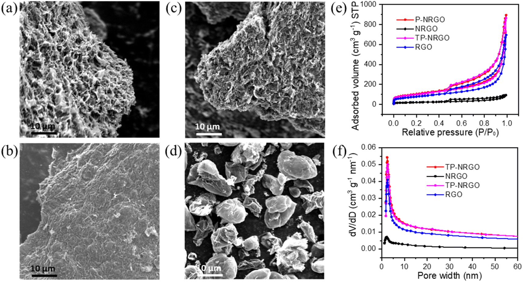 | ||
| Fig. 1 SEM images of (a) P-NRGO, (b) NRGO, (c) TP-NRGO and (d) RGO. (e) N2 adsorption/desorption isotherms of P-NRGO, NRGO, TP-NRGO and RGO. (f) Cumulative pore volumes and pore-size distributions of P-NRGO, NRGO, TP-NRGO and RGO. | ||
XPS measurements were performed to confirm the detailed surface chemistry of the four graphene materials. XPS spectra (Fig. 2a) reveal that the P-NRGO, NRGO and TP-NRGO materials are mainly composed of C, N and O, and RGO is mainly composed of C and O. For the P-NRGO, NRGO and TP-NRGO, the C 1s spectra could be deconvoluted into four subpeaks at 284.7, 285.2, 286.6 and 289.0 eV (Fig. 2b–d), which are arising from C–C, C–N, C–O and C–O![[double bond, length as m-dash]](https://www.rsc.org/images/entities/char_e001.gif) C, respectively.43,44 The deconvoluted C 1s spectrum of RGO consists of only C–C, C–O and C–OC (Fig. 2e). The high-resolution N 1s XPS spectra (Fig. 2f–h) can be fitted with four different types of nitrogen species, namely pyridinic N (398.7 eV), pyrrolic N (399.9 eV), graphitic N (401.1 eV), and oxidized N (N–O) (402.4 eV).45,46 The contents of each type of nitrogen species in P-NRGO, NRGO and TP-NRGO are summarized in Table S1.† The atomic ratio of nitrogen in TP-NRGO (3.24 at%) decreases compared to that of P-NRGO (7.76 at%), suggesting the decrease of nitrogen species in TP-NRGO by increasing the heating time. Furthermore, the atomic ratio of oxygen in RGO (21.12 at%) is higher than those of P-NRGO (18.68 at%), NRGO (18.12 at%) and TP-NRGO (6.34 at%), indicating a high concentration of the oxygen-containing functional groups in RGO. The corresponding elementary compositions of the four graphene materials are summarized in Table 1. The typical Raman spectra (Fig. S4†) of the GO, P-NRGO, NRGO, TP-NRGO and RGO materials are characterized by two major peaks appearing at ∼1340 and 1584 cm−1, which can be ascribed to the disordered defective graphite (D band) and the ordered crystal graphite (G band), respectively.47 The D/G intensity ratios (ID/IG) of P-NRGO (1.045), NRGO (1.032) and TP-NRGO (1.015) are higher than those of RGO (1.004) and GO (0.983), demonstrating the successful incorporation of N atoms in the graphene that could introduce a large number of topological defects.31,48
C, respectively.43,44 The deconvoluted C 1s spectrum of RGO consists of only C–C, C–O and C–OC (Fig. 2e). The high-resolution N 1s XPS spectra (Fig. 2f–h) can be fitted with four different types of nitrogen species, namely pyridinic N (398.7 eV), pyrrolic N (399.9 eV), graphitic N (401.1 eV), and oxidized N (N–O) (402.4 eV).45,46 The contents of each type of nitrogen species in P-NRGO, NRGO and TP-NRGO are summarized in Table S1.† The atomic ratio of nitrogen in TP-NRGO (3.24 at%) decreases compared to that of P-NRGO (7.76 at%), suggesting the decrease of nitrogen species in TP-NRGO by increasing the heating time. Furthermore, the atomic ratio of oxygen in RGO (21.12 at%) is higher than those of P-NRGO (18.68 at%), NRGO (18.12 at%) and TP-NRGO (6.34 at%), indicating a high concentration of the oxygen-containing functional groups in RGO. The corresponding elementary compositions of the four graphene materials are summarized in Table 1. The typical Raman spectra (Fig. S4†) of the GO, P-NRGO, NRGO, TP-NRGO and RGO materials are characterized by two major peaks appearing at ∼1340 and 1584 cm−1, which can be ascribed to the disordered defective graphite (D band) and the ordered crystal graphite (G band), respectively.47 The D/G intensity ratios (ID/IG) of P-NRGO (1.045), NRGO (1.032) and TP-NRGO (1.015) are higher than those of RGO (1.004) and GO (0.983), demonstrating the successful incorporation of N atoms in the graphene that could introduce a large number of topological defects.31,48
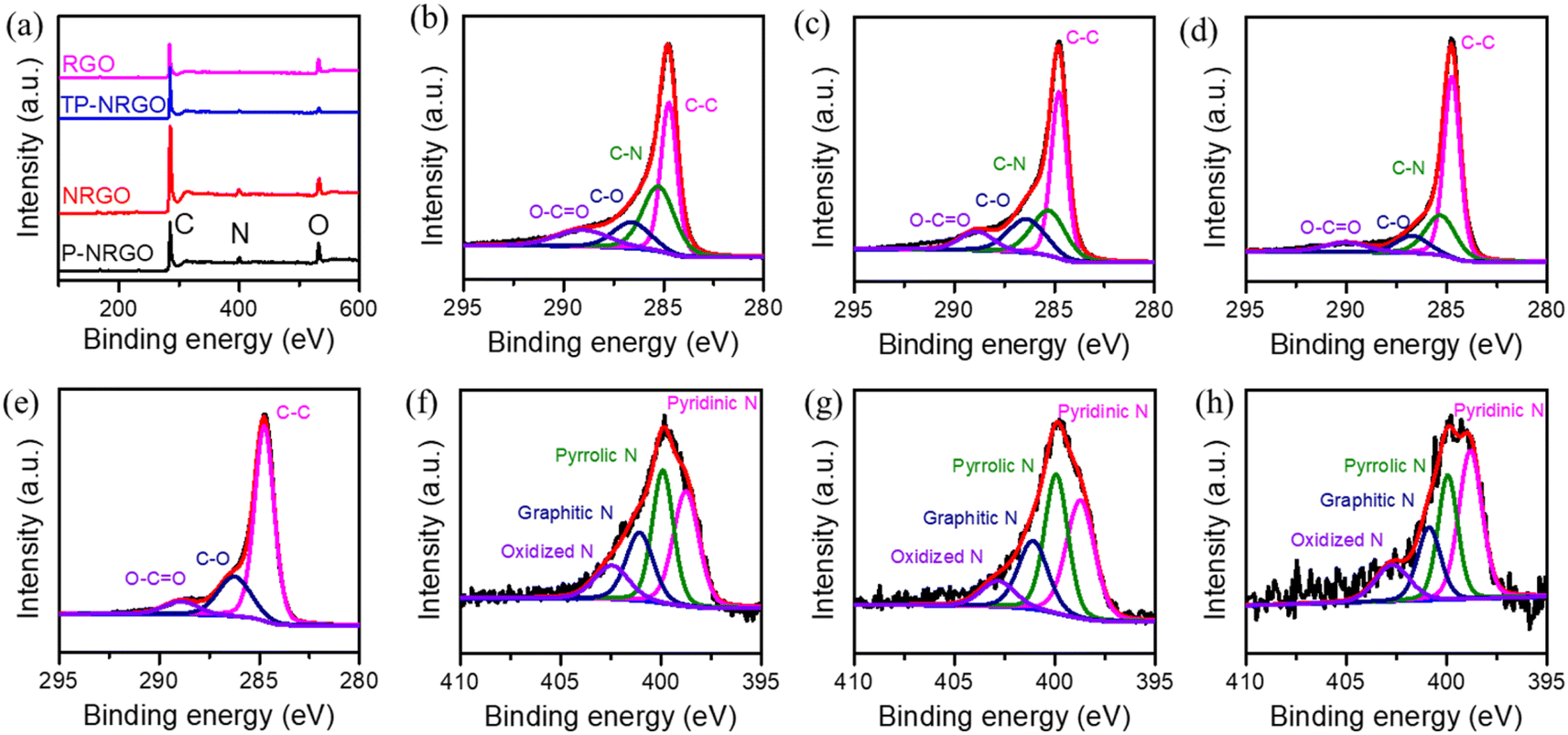 | ||
| Fig. 2 (a) XPS spectra of the four graphene materials. High-resolution C 1s XPS spectra of (b) P-NRGO, (c) NRGO, (d) TP-NRGO and (e) RGO. High-resolution N 1s XPS spectra of (f) P-NRGO, (g) NRGO and (h) TP-NRGO. | ||
| Atomic ratio | P-NRGO | NRGO | TP-NRGO | RGO |
|---|---|---|---|---|
| C (at%) | 73.16 | 74.34 | 90.42 | 78.74 |
| N (at%) | 7.76 | 7.54 | 3.24 | 0.14 |
| O (at%) | 18.68 | 18.12 | 6.34 | 21.12 |
Pt particles were impregnated in P-NRGO, NRGO, TP-NRGO and RGO via a glycol reduction process. The XRD patterns of the four Pt/graphene catalysts (Fig. 3a) show peaks at 39.81°, 46.12°, and 67.45° corresponding to the (111), (200) and (220) planes, respectively, of crystalline Pt.34 Moreover, Pt/RGO exhibits the lowest full width at half maximum (FWHM) among the four Pt/graphene catalysts, indicating the larger size of Pt particles on RGO than those on the other three graphene materials. The TGA (Fig. 3b) shows that the Pt contents are around 40 wt% for all of the four Pt/graphene catalysts. The fast Fourier transform (FFT) patterns (Fig. 4c, f, i and l) show clear hexagonal diffractions, demonstrating well-crystallized Pt nanoparticles in the four Pt/graphene catalysts. The d-spacing of the (111) lattice fringe of Pt nanoparticles in the four Pt/graphene catalysts is about 0.22 nm (Fig. S5†). The TEM images (Fig. 4) indicate that the Pt particles have different average diameters of 2.4, 4.5, 4.5 and 6 nm on P-NRGO, NRGO, TP-NRGO and RGO, respectively. The significantly larger SSA and pore volume of P-NRGO (370.4 m2 g−1 and 1.366 cm3 g−1) and TP-NRGO (347.7 m2 g−1 and 1.3299 cm3 g−1) than those of NRGO (70.6 m2 g−1 and 0.1424 cm3 g−1) provides more space for Pt adhering, which is favorable for forming smaller Pt particles.49 However, the average particle size of Pt on TP-NRGO is larger than that on P-NRGO. This phenomenon may be ascribed to the higher N content of P-NRGO than that of TP-NRGO, which favors the uniform dispersion of Pt particles on the graphene support.50,51 Moreover, the average diameter of the Pt particles on RGO is larger than that on NRGO though the SSA and pore volume of RGO are larger than those of NRGO, which may be ascribed to the high oxygen-containing functional groups in RGO. The oxygen-containing functional groups interact strongly with Pt catalyst precursor species, thus inhibit the uniform dispersion of Pt particles.21 These results indicate that the SSA and heteroatom dopants have strong influences on the size of Pt particles. Specifically, large SSA, large volume and high content of nitrogen species are beneficial for the deposition of uniformly sized Pt particles on the graphene materials, and the nitrogen species of graphene supports play a more important role than the oxygen species, SSA and pore volume for the Pt/graphene catalysts in helping the uniform dispersion of Pt particles.
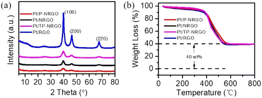 | ||
| Fig. 3 (a) XRD patterns and (b) TG curves of the Pt/P-NRGO, Pt/NRGO, Pt/TP-NRGO and Pt/RGO catalysts. | ||
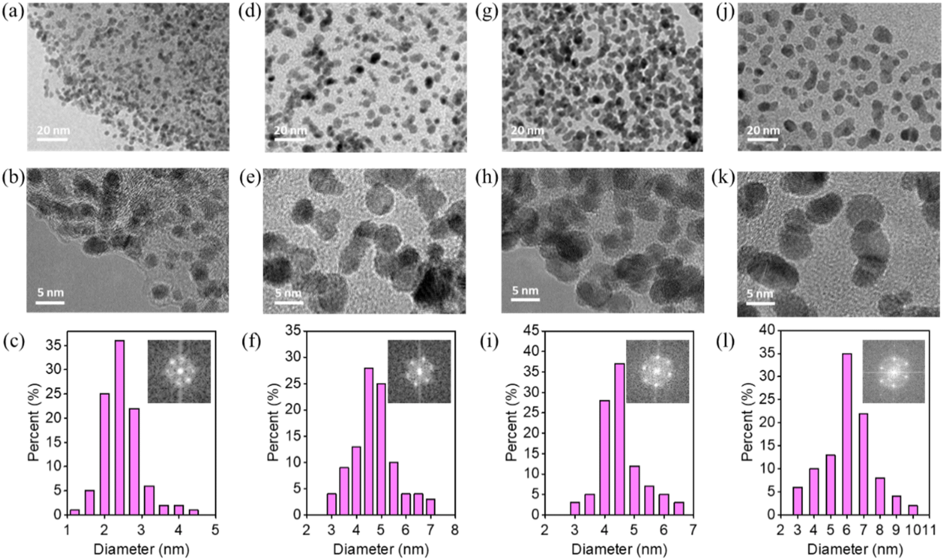 | ||
| Fig. 4 TEM images of (a and b) Pt/P-NRGO, (d and e) Pt/NRGO, (g and h) Pt/TP-NRGO and (j and k) Pt/RGO at different magnifications. Pt particle size distribution results and insets of the FFT patterns of (c) Pt/P-NRGO, (f) Pt/NRGO, (i) Pt/TP-NRGO and (l) Pt/RGO. | ||
To reveal the surface chemistry of Pt/graphene catalysts, the surface characteristics of the four Pt/graphene catalysts were characterized by XPS, and the results are displayed in Fig. 5 and S6.† Nitrogen atoms in the Pt/P-NRGO, Pt/NRGO and Pt/TP-NRGO catalysts are present in the form of pyridinic (398.7 eV), pyrrolic (399.9 eV), graphitic (400.7 eV) and oxidized N groups (402.4 eV). It is interesting to note that only the N 1s peak, assigned to graphitic N of the three Pt/graphene catalysts (Pt/P-NRGO, Pt/NRGO, and Pt/TP-NRGO), down-shifts by ∼0.4 eV with respect to its position in graphene (401.1 eV, Fig. 2f–h), suggesting that Pt in the Pt/P-NRGO, Pt/NRGO, and Pt/TP-NRGO catalysts is bound to graphitic N.52,53 The contents of each type of nitrogen species in Pt/P-NRGO, Pt/NRGO and Pt/TP-NRGO are summarized in Table S2.† It can be seen that Pt/P-NRGO (21.72%) and Pt/NRGO (21.05%) have a higher content of graphitic N than Pt/TP-NRGO (19.49%). The Pt 4f spectra show that the Pt binding energy of the Pt/P-NRGO, Pt/NRGO, and Pt/TP-NRGO catalysts shifts towards a higher value than that of Pt/RGO, implying that Pt particles interact with graphene supports in the Pt/P-NRGO, Pt/NRGO and Pt/TP-NRGO catalysts,31 which is in accordance with the N 1s spectra analysis. The interaction between graphitic N and Pt is conducive to anchoring Pt particles, and therefore, it inhibits the growth of Pt particles,54 making the size of Pt particles in Pt/P-NRGO, Pt/NRGO, and Pt/TP-NRGO lower than that in Pt/RGO (Fig. 4). The O 1s signal of the four Pt/graphene catalysts (Fig. S6†) consists of component peaks at 531.1, 532.3 and 533.5 eV, corresponding to Pt–O and CO, C–O, and OC–O, respectively.55–57 The Pt 4f spectra show that the percentage (50.6%) of Pt2+ (Pt–O) in Pt/RGO (Fig. 5h) is much higher than those of Pt/P-NRGO (30.9%, Fig. 5e), Pt/NRGO (29.4%, Fig. 5f) and Pt/TP-NRGO (44.4%, Fig. 5g) due to the high oxygen content and almost absence of N species in RGO, suggesting a stronger interaction between oxygen species and Pt in the Pt/RGO catalyst than those in the Pt/P-NRGO, Pt/NRGO and Pt/TP-NRGO catalysts.25,58 The strong interaction between oxygen species and Pt in Pt/RGO is not conducive to the uniform dispersion of Pt particles, and thus results in a larger Pt particle size on RGO.25,58
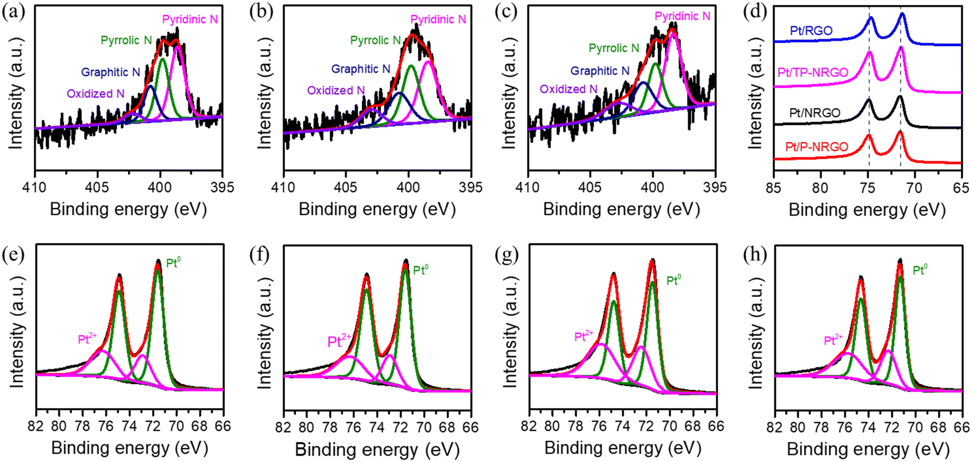 | ||
| Fig. 5 XPS spectra of the four Pt/graphene catalysts. High-resolution N 1s XPS spectra of (a) Pt/P-NRGO, (b) Pt/NRGO and (c) Pt/TP-NRGO. (d) Pt 4f XPS spectra of the four Pt/graphene catalysts. High-resolution Pt 4f XPS spectra of (e) Pt/P-NRGO, (f) Pt/NRGO, (g) Pt/TP-NRGO and (h) Pt/RGO. | ||
3.2. Electrochemical performance
The intrinsic ORR electro-catalytic performances of the four Pt/graphene catalysts were tested in 0.5 M H2SO4 electrolyte and compared with the commercial Pt/C (40 wt% Pt on Vulcan XC72R carbon) catalyst. In the H2SO4 electrolyte, sulfate ions have specific adsorption on Pt particles, which may reduce the ORR catalytic activity of the catalyst.59 Since Pt particles in the Pt/graphene and Pt/C catalysts have the same crystal structure and the same content (Fig. 3 and S7†), the use of H2SO4 electrolytes has little impact on the results of performance comparison in this study. Fig. 6a depicts the CV curves measured in a N2-saturated 0.5 M H2SO4 electrolyte in the range of 0.0–1.2 V vs. RHE at a scan rate of 50 mV s−1. Pt/P-NRGO, Pt/NRGO, Pt/TP-NRGO and Pt/RGO deliver electrochemical active surface areas (ECSA) of 97.4, 84.7, 87.1 and 40.6 m2 g−1, respectively, compared with 84.2 m2 g−1 for the commercial Pt/C catalyst. The utilization rate of the active sites of Pt particles determines the ECSA.4,8,60 The higher ECSA of Pt/P-NRGO than those of the other three Pt/graphene catalysts may be ascribed to the high porosity of the P-NRGO support and the uniform dispersion of Pt particles in the P-NRGO support. Pt/RGO has the lowest ECSA, mainly due to the large size of Pt particles in the catalyst with fewer available active sites.6,61 Although the average diameter of Pt on the NRGO is comparable to that on TP-NRGO, Pt/NRGO has a slightly lower ECSA, indicating that the graphene sheets stacking in NRGO inhibit the diffusion of oxygen molecules to the Pt active sites.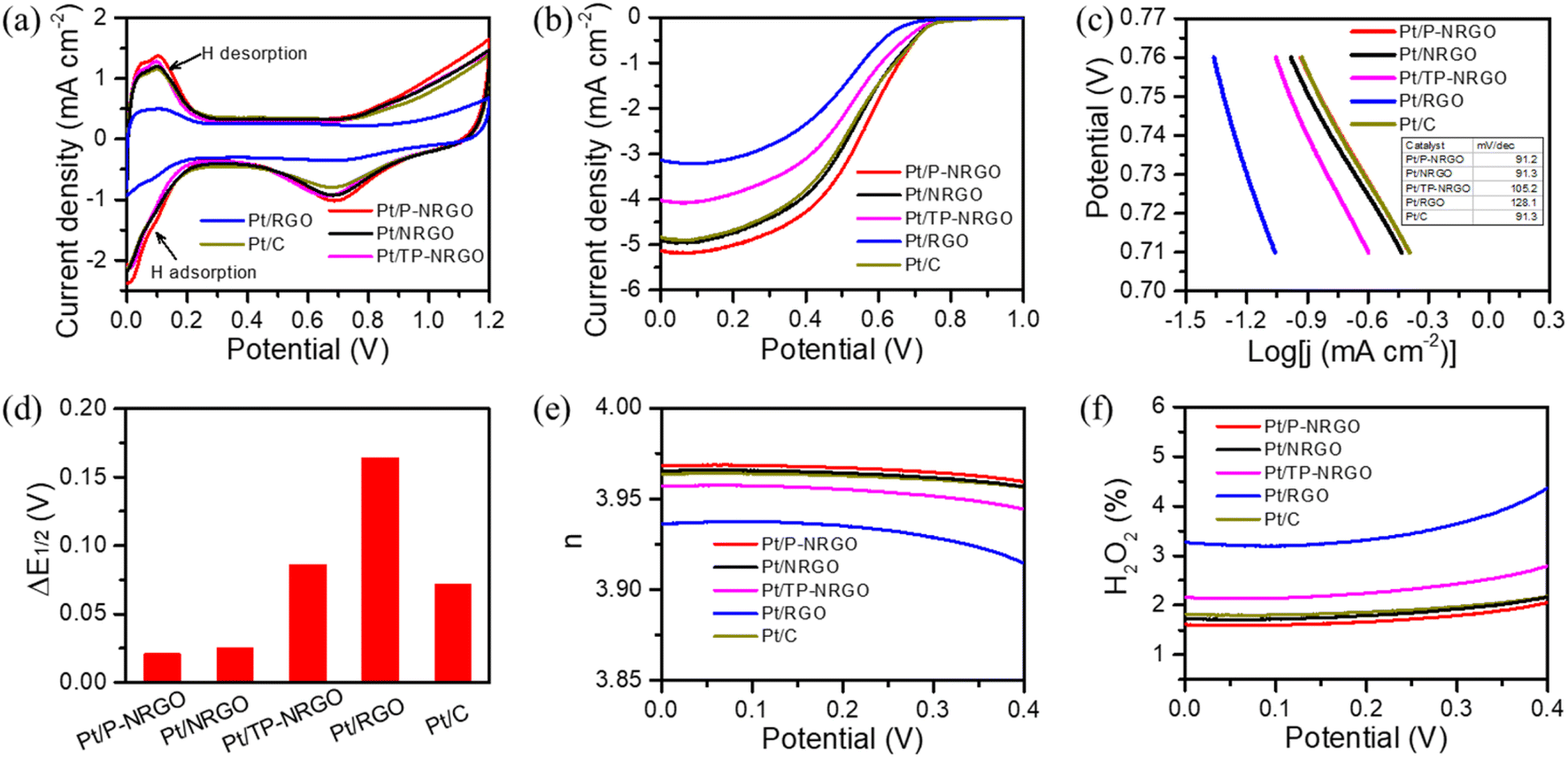 | ||
| Fig. 6 ORR activity performances of the catalysts in a 0.5 M H2SO4 electrolyte. (a) CV and (b) ORR polarization curves of Pt/P-NRGO, Pt/NRGO, Pt/TP-NRGO, Pt/RGO and Pt/C catalysts. CV curves were performed in a N2-saturated electrolyte at a scan rate of 50 mV s−1. ORR polarization curves were conducted in an O2-saturated electrolyte at a scan rate of 10 mV s−1 and a rotation of 1600 rpm. (c) Tafel slopes of Pt/P-NRGO, Pt/NRGO, Pt/TP-NRGO, Pt/RGO and Pt/C catalysts. (d) ΔE1/2 for Pt/P-NRGO, Pt/NRGO, Pt/TP-NRGO, Pt/RGO and Pt/C catalysts from the initial to the 10000th cycle of CV in O2-saturated 0.5 M H2SO4. Here, CV was performed in an O2-saturated electrolyte at a scan rate of 50 mV s−1. (e) Electron transfer number (n) values and (f) H2O2 yields of Pt/P-NRGO, Pt/NRGO, Pt/TP-NRGO, Pt/RGO and Pt/C in O2-saturated 0.5 M H2SO4 at a scan rate of 10 mV s−1 and a speed of 1600 rpm. | ||
The ORR polarization curves of the four Pt/graphene catalysts (Fig. 6b) and the four graphene materials (Fig. S8†) were obtained in an O2-saturated 0.5 M H2SO4 electrolyte in the range of 0.0–1.0 V vs. RHE at a scan rate of 10 mV s−1 and a speed of 1600 rpm. The catalytic performances of P-NRGO, NRGO and TP-NRGO are apparently higher than that of RGO (Fig. S8†), suggesting that the nitrogen species in the graphene support are the active sites for the ORR. It has been reported that the half-wave potential (E1/2) represents the catalytic activity of the catalyst.31,62 The E1/2 values are 0.558, 0.523, 0.503, 0.491 and 0.523 V, respectively, for the Pt/P-NRGO, Pt/NRGO, Pt/TP-NRGO, Pt/RGO and Pt/C catalysts. Remarkably, the E1/2 value of Pt/NRGO exceeds that of Pt/TP-NRGO, and is comparable to that of Pt/C, although Pt/NRGO has a lower ECSA than that of Pt/TP-NRGO. The specific activity (SA) and mass activity (MA) of Pt/NRGO are 0.53 mA cm−2 and 0.45 A mgPt−1, respectively, both of which are higher than those of Pt/TP-NRGO (Table S3†). The higher catalytic activity of Pt/NRGO than that of Pt/TP-NRGO can be ascribed to the higher nitrogen content of NRGO than that of TP-NRGO (Table 1), and the defects caused by nitrogen doping are conducive to the adsorption of O species and catalyze the ORR.14,63 These results indicate that the nitrogen content in the graphene support contributes more to the catalytic activity of ORRs than the SSA, and that a higher nitrogen content in the graphene support provides more accessible active sites for ORRs. The Tafel curves (Fig. 6c) obtained from the LSV curves show that the Tafel slopes of Pt/P-NRGO (91.2 mV dec−1), Pt/NRGO (91.3 mV dec−1) and Pt/TP-NRGO (105.2 mV dec−1) are lower than that of Pt/RGO (128.1 mV dec−1). In addition, the exchange current densities of Pt/P-NRGO, Pt/NRGO, Pt/TP-NRGO, Pt/RGO and Pt/C are 20.85, 20.69, 18.35, 15.49 and 20.69 mA cm−2, respectively. The lower Tafel slopes and higher exchange current densities of Pt/P-NRGO, Pt/NRGO and Pt/TP-NRGO than that of Pt/RGO further manifest that the nitrogen species in the support are the active sites for ORRs and that nitrogen species contribute to the ORR kinetic process in Pt/P-NRGO, Pt/NRGO and Pt/TP-NRGO. Therefore, the Pt/P-NRGO catalyst exhibits a higher catalytic activity than that of the other three Pt/graphene catalysts due to the high nitrogen content in P-NRGO and the high ECSA of Pt/P-NRGO. Pt/RGO has the lowest electro-catalytic activity. Though the oxygen species may help in creating a favorable three-phase interface to facilitate the ORR,64 the high oxygen content of RGO does not help in improving the electro-catalytic activity of the Pt/RGO catalyst in this study. This phenomenon may be ascribed to the largest Pt particle size of the Pt/RGO catalyst among the four Pt/graphene catalysts, which provides few accessible active sites for the ORR.8,13
In order to investigate the durability of the four Pt/graphene catalysts, the ORR polarization curves for the four Pt/graphene catalysts before and after the 10000th cycle of CV were compared (Fig. S9†), and the ΔE1/2 value was accordingly extracted (Fig. 6d). The ΔE1/2 value for Pt/P-NRGO, Pt/NRGO, Pt/TP-NRGO, Pt/RGO and Pt/C is 0.021, 0.025, 0.086, 0.164 and 0.072 V, respectively. This implies that Pt/P-NRGO and Pt/NRGO have a considerable stability over multicycle use, and that Pt/P-NRGO and Pt/NRGO have a better stability than those of the other two Pt/graphene catalysts in this work and the commercial Pt/C catalyst. The excellent durability of Pt/P-NRGO and Pt/NRGO can be attributed to the high graphitic N content in P-NRGO and NRGO, which helps Pt species adhesion on the graphene support.65,66
To understand the ORR pathways of the four Pt/graphene catalysts, RRDE measurements were performed to estimate the electron transfer number (n) and monitor the formation of peroxide species (H2O2) during the ORR process. The electron transfer number (n) and the percentage of H2O2 were estimated using eqn (1) and (2). As shown in Fig. 6e, the n values of the four Pt/graphene catalysts derived from the RRDE measurements range from 3.92 to 3.97. Notably, the n values of Pt/P-NRGO and Pt/NRGO are higher than those of Pt/TP-NRGO and Pt/RGO over the whole measurement range of 0.0–0.4 V. A significantly low H2O2 content (below 2.2%) was observed for Pt/P-NRGO and Pt/NRGO, which is comparable to that of the commercial Pt/C catalyst (Fig. 6f). However, the H2O2 percentage produced by Pt/TP-NRGO and Pt/RGO is close to 3% and 4.5%, respectively, higher than that of the commercial Pt/C catalyst. Based on this evidence, it could be proposed that the four Pt/graphene catalysts in this work tend to catalyze the ORR via a four-electron pathway, and that Pt/P-NRGO and Pt/NRGO exhibit a higher efficiency and a lower by-product yield during the ORR process compared with Pt/TP-NRGO and Pt/RGO. The fast kinetic process of Pt/P-NRGO and Pt/NRGO can be ascribed to the high content of nitrogen species, which provide accessible active sites for ORRs.14,63
The comparison of Pt/P-NRGO, Pt/NRGO, Pt/TP-NRGO, Pt/RGO and Pt/C in H2–air PEMFCs is displayed in Fig. 7a. Pt/P-NRGO (0.76 W cm−2) has the highest peak power density compared to the other three Pt/graphene catalysts, which is in accordance with ORR polarization curves of the four Pt/graphene catalysts (Fig. 6b). The peak power density of the H2–air PEMFCs reaches Pt/P-NRGO > Pt/C > Pt/NRGO > Pt/TP-NRGO > Pt/RGO. This result indicates a much better utilization of active sites for the Pt/P-NRGO catalyst in H2–air PEMFCs than for the other three Pt/graphene catalysts, owing to the porous structure and high nitrogen content of P-NRGO. The cell performance of Pt/NRGO was decreased compared to that of Pt/C though the ORR performances of Pt/NRGO and Pt/C are very close (Fig. 6b), which may be ascribed to the fact that the graphene sheets tend to agglomerate during the preparation of the catalyst layer, hindering the reactant diffusion and product transport.23
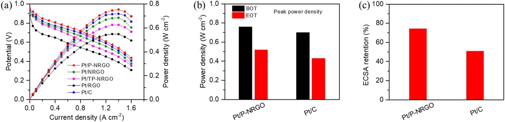 | ||
| Fig. 7 (a) Single cell performances of H2–air PEMFCs recorded on MEAs with Pt/P-NRGO, Pt/NRGO, Pt/TP-NRGO, Pt/RGO and Pt/C as cathode catalysts. (b) Comparison of peak power densities at the BOT and EOT for Pt/P-NRGO and Pt/C catalysts. (c) ECSA retentions from the BOT to the EOT of Pt/P-NRGO and Pt/C catalysts. The MEA tests were performed at 75 °C, 150 kPaabs (abs: absolute) and 100% RH. | ||
The durability of the MEA performance is a serious factor for evaluating the stability of catalysts for practical H2–air PEMFCs. Since Pt/P-NRGO shows the best electro-catalytic property among the four Pt/graphene catalysts in this study, it was selected for testing and compared with the commercial Pt/C catalyst in the durability investigation of the MEA. In order to test the practical durability of Pt/P-NRGO and Pt/C catalysts in the MEA, an accelerated durability test (ADT) was conducted. In the ADT for catalysts, a square wave voltage from 0.6 to 0.95 V with a duration of 3 s at each voltage was applied on the MEA for 30000 cycles. As shown in Fig. 7b and S10,† the peak power densities of Pt/P-NRGO at the beginning of test (BOT) and end of test (EOT) are 0.76 and 0.52 W cm−2, respectively, which are higher than those of commercial Pt/C (0.70 and 0.43 W cm−2 at BOT and DOT, respectively). Pt/P-NRGO has a power retention rate of 68% after 30000 cycles of square wave ADT, higher than that of commercial Pt/C (61%, Fig. S11†). The CV curves in the MEA were also tested at the BOT and EOT (Fig. S12†). The MEA based on Pt/P-NRGO retains more than 70% of initial ECSA (MEA) after 30000 cycles of square-wave ADT, much higher than that of commercial Pt/C (50%, Fig. 7c). These results indicate that the long-term durability of Pt/P-NRGO for the operation of H2–air PEMFCs is better than that of the Pt/C catalyst.
Furthermore, TEM images, XRD patterns, and Raman spectra were recorded using Pt/P-NRGO and Pt/C catalysts after the 30000 cycles of square-wave ADT to investigate the structural stability of catalysts. The Pt particles in Pt/C exhibit obvious aggregation (Fig. S13†), with the average size of Pt particles increasing from 3 (BOT) to 4 nm (EOT). The XRD pattern of Pt/C at the EOT shows a lower FWHM than that at the BOT (Fig. S14b†), further confirming the aggregation of Pt particles at the EOT. An obvious change in Raman spectra is observed for Pt/C after ADT (Fig. S15b†), indicating the instability of the carbon support in the Pt/C catalyst. The size coarsening for Pt/P-NRGO can also be observed, but to a much less degree (Fig. 4a–c and 8a–c). The sizes of Pt particles in Pt/P-NRGO at the BOT and EOT are 2.4 and 2.8 nm, respectively (Fig. 4c and 8c). The coarsening of Pt particles gives rise to a decrease in Pt active sites, which contributes to the observed MEA performance degradation at the EOT (Fig. 7b and c). No obvious changes can be observed in the FFT patterns (Fig. 4c and 7c), XRD patterns (Fig. S14a†) and Raman spectra (Fig. S15a†) for Pt/P-NRGO at EOT, further confirming that the morphology, crystallinity, and lattice spacing of Pt/P-NRGO are well kept after the 30000 cycles of square-wave ADT. The remarkable structural stability of Pt/P-NRGO is related to high graphitic nitrogen species content in P-NRGO (see Tables S1 and S2†), which helps Pt species adhesion on the graphene support65,66 and the structure stability of the P-NRGO support, as indicated in the Raman results (Fig. S15a†).
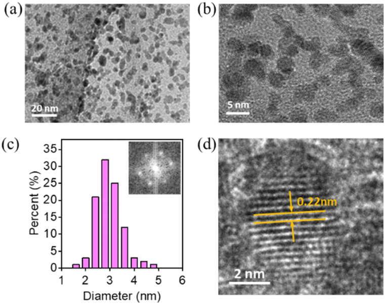 | ||
| Fig. 8 (a and b) TEM images with different magnifications for Pt/P-NRGO at the EOT. (c) Pt particle size distribution; inset: FFT pattern of Pt/P-NRGO at the EOT. (d) High-resolution TEM image showing the lattice and d-spacing value of Pt/P-NRGO at the EOT. | ||
4. Conclusions
In summary, we have synthetized four types of graphene materials and studied the relevance of the structural features (SSA, pore volume, nitrogen content and oxygen content) of graphene supports to the electro-catalytic properties of the Pt/graphene catalysts. The Pt/P-NRGO catalyst delivers the best electro-catalytic performance among the four Pt/graphene catalysts, while P-NRGO has a high concentration of nitrogen species of 7.76 at%, a moderate concentration of oxygen species of 18.68 at% and a high SSA of 370.4 m2 g−1 with an average pore volume of 1.366 cm3 g−1. Furthermore, the ORR catalytic activity of the four Pt/graphene catalysts reaches Pt/P-NRGO > Pt/NRGO > Pt/TP-NRGO > Pt/RGO when listed in the order of their E1/2 and peak power density, and the long-term durability of Pt/P-NRGO for the operation of H2–air PEMFCs is better than that of the commercial Pt/C catalyst. Combining the results from TEM, XPS and H2–air PEMFCs, we conclude that the SSA and heteroatom dopant have a strong influence on the size of Pt particles, and that the nitrogen species of graphene supports play a more important role than the oxygen species, SSA and pore volume for the Pt/graphene catalysts in providing accessible active sites. Furthermore, our results can pave the way to designing advanced graphene supports for graphene-based ORR catalysts of PEMFCs.Data availability
The data supporting this article have been included as part of the ESI.†Conflicts of interest
There are no conflicts to declare.Acknowledgements
This study is supported by the Stabilization Support Program. The authors are also grateful to Beijing General Research Institute for Nonferrous Metals for providing support with the microstructure characterization.References
- W. Hwang and Y. E. Sung, J. Electrochem. Sci. Technol., 2023, 14, 120–130 CrossRef CAS.
- Y. Wang, Y. H. Pang, H. Xu, A. Martinez and K. S. Chen, Energy Environ. Sci., 2022, 15, 2288–2328 RSC.
- K. Jiao, J. Xuan, Q. Du, Z. M. Bao, B. A. Xie, B. W. Wang, Y. Zhao, L. H. Fan, H. Z. Wang, Z. J. Hou, S. Huo, N. P. Brandon, Y. Yin and M. D. Guiver, Nature, 2021, 595, 361–369 CrossRef CAS.
- M. H. Tang, S. M. Zhang and S. L. Chen, Chem. Soc. Rev., 2022, 51, 1529–1546 RSC.
- Z. P. Zhao, C. L. Chen, Z. Y. Liu, J. Huang, M. H. Wu, H. T. Liu, Y. J. Li and Y. Huang, Adv. Mater., 2019, 31, 1808115 CrossRef.
- Q. Sun, X. H. Li, K. X. Wang, T. N. Ye and J. S. Chen, Energy Environ. Sci., 2023, 16, 1838–1869 RSC.
- M. X. Du, D. Li, S. Liu and J. Q. Yan, Adv. Funct. Mater., 2023, 33, 2301527 CrossRef CAS.
- S. Sui, X. Y. Wang, X. T. Zhou, Y. H. Su, S. Riffatc and C. J. Liu, J. Mater. Chem. A, 2017, 5, 1808–1825 RSC.
- L. X. Fan, J. J. Zhao, X. B. Luo and Z. K. Tu, Int. J. Hydrogen Energy, 2022, 47, 5418–5428 CrossRef CAS.
- L. Castanheira, W. O. Silva, F. H. B. Lima, A. Crisci, L. Dubau and F. Maillard, ACS Catal., 2015, 5, 2184–2194 CAS.
- J. J. Zhao, Z. K. Tu and S. H. Chan, J. Power Sources, 2021, 488, 229434 CAS.
- N. Seselj, S. M. Alfaro, E. Bompolaki, L. N. Cleemann, T. Torres and K. Azizi, Adv. Mater., 2023, 35, 2302207 CrossRef CAS.
- P. C. Okonkwo, O. O. Ige, E. Barhoumi, P. C. Uzoma, W. Emori, A. Benamor and A. M. Abdullah, Int. J. Hydrogen Energy, 2021, 46, 15850–15865 CrossRef CAS.
- Y. Xu, R. K. Xie, Q. Li, J. Y. Feng, H. Luo, Q. Y. Ye, Z. Y. Guo, Y. Cao, M. Palma, G. L. Chai, M. M. Titirici and C. R. Jones, Small, 2023, 19, 2302795 CrossRef CAS.
- G. V. Fortunato, F. de Lima and G. Maia, J. Power Sources, 2016, 302, 247–258 CrossRef CAS.
- Z. P. Zhao, Z. Y. Liu, A. Zhang, X. X. Yan, W. Xue, B. S. Peng, H. L. Xin, X. Q. Pan, X. F. Duan and Y. Huang, Nat. Nanotechnol., 2022, 17, 968–975 CrossRef CAS.
- S. Hussain, H. Erikson, N. Kongi, A. Tarre, P. Ritslaid, M. Kook, M. Rähn, M. Merisalu, V. Sammelselg and K. Tammeveski, J. Electrochem. Soc., 2019, 166, F1284–F1291 CrossRef CAS.
- S. Hussain, H. Erikson, N. Kongi, M. Merisalu, P. Ritslaid, V. Sammelselg and K. Tammeveski, Int. J. Hydrogen Energy, 2017, 42, 5958–5970 CrossRef CAS.
- M. Wang, M. Huang, D. Luo, Y. Li, M. Choe, W. K. Seong, M. Kim, S. Jin, M. Wang, S. Chatterjee, Y. Kwon, Z. Lee and R. S. Ruoff, Nature, 2021, 596, 519–524 CrossRef CAS PubMed.
- F. Bonaccorso, L. Colombo, G. H. Yu, M. Stoller, V. Tozzini, A. C. Ferrari, R. S. Ruoff and V. Pellegrini, Science, 2015, 347, 1246501 CrossRef.
- D. Higgins, P. Zamani, A. Yu and Z. Chen, Energy Environ. Sci., 2016, 9, 357–390 RSC.
- M. Samancı and A. Bayrakçeken Yurtcan, Int. J. Hydrogen Energy, 2022, 47, 19669–19689 CrossRef.
- Y. Li, Y. Li, E. Zhu, T. McLouth, C. Y. Chiu, X. Huang and Y. Huang, J. Am. Chem. Soc., 2012, 134, 12326–12329 CrossRef CAS PubMed.
- N. Manna, M. Singh and S. Kurungot, ACS Appl. Mater. Interfaces, 2023, 15, 28023–28035 CrossRef CAS PubMed.
- M. Li, Q. Jiang, M. Yan, Y. Wei, J. Zong, J. Zhang, Y. Wu and H. Huang, ACS Sustainable Chem. Eng., 2018, 6, 6644–6653 CrossRef CAS.
- K. Cheng, D. He, T. Peng, H. Lv, M. Pan and S. Mu, Electrochim. Acta, 2014, 132, 356–363 CrossRef CAS.
- M. Lei, C. Liang, Y. J. Wang, K. Huang, C. X. Ye, G. Liu, W. J. Wang, S. F. Jin, R. Zhang, D. Y. Fan, H. J. Yang and Y. G. Wang, Electrochim. Acta, 2013, 113, 366–372 CrossRef CAS.
- X. Chen, M. Peng, X. Cai, Y. Chen, Z. Jia, Y. Deng, B. Mei, Z. Jiang, D. Xiao, X. Wen, N. Wang, H. Liu and D. Ma, Nat. Commun., 2021, 12, 2664 CrossRef CAS PubMed.
- I. Y. Jeon, H. J. Choi, S. M. Jung, J. M. Seo, M. J. Kim, L. M. Dai and J. B. Baek, J. Am. Chem. Soc., 2013, 135, 1386–1393 CrossRef CAS.
- Y. B. Sun, R. X. Deng, C. Chi, X. L. Chen, Y. A. Pan, J. Li and X. H. Xia, J. Electroanal. Chem., 2023, 940, 117489 CrossRef CAS.
- P. Q. Phan, R. Naraprawatphong, P. Pornaroontham, J. Park, C. Chokradjaroen and N. Saito, Mater. Adv., 2021, 2, 322–335 RSC.
- R. Siburian, K. Sebayang, M. Supeno and H. Marpaung, Chemistryselect, 2017, 2, 1188–1195 CrossRef CAS.
- F. H. Li, Y. Q. Guo, Y. Liu, J. Yan, W. Wang and J. P. Gao, Carbon, 2014, 67, 617–626 CrossRef CAS.
- H. Huang, X. Guo, M. Yan, W. Meng, Y. Xue, D. Xiao, Q. Jiang, L. Yang and H. He, Mater. Today Energy, 2021, 21, 100814 CrossRef CAS.
- M. A. Hoque, F. M. Hassan, M. H. Seo, J. Y. Choi, M. Pritzker, S. Knights, S. Y. Ye and Z. W. Chen, Nano Energy, 2016, 19, 27–38 CrossRef CAS.
- D. Higgins, M. A. Hoque, M. H. Seo, R. Y. Wang, F. Hassan, J. Y. Choi, M. Pritzker, A. P. Yu, J. J. Zhang and Z. W. Chen, Adv. Funct. Mater., 2014, 24, 4325–4336 CrossRef CAS.
- X. X. Zhan, X. Tong, M. Q. Gu, J. Tian, Z. J. Gao, L. Y. Ma, Y. D. Xie, Z. S. Chen, H. Ranganathan, G. X. Zhang and S. H. Sun, Nanomater., 2022, 12, 1141 CrossRef CAS PubMed.
- X. H. Zou, Z. S. Li, Y. X. Xie, H. Wu and S. Lin, Int. J. Hydrogen Energy, 2020, 45, 30647–30658 CrossRef CAS.
- S. Park, J. An, R. D. Piner, I. Jung, D. Yang, A. Velamakanni, S. T. Nguyen and R. S. Ruoff, Chem. Mater., 2008, 20, 6592–6594 CrossRef CAS.
- Y. Zhu, S. Murali, M. D. Stoller, A. Velamakanni, R. D. Piner and R. S. Ruoff, Carbon, 2010, 48, 2118–2122 CrossRef CAS.
- Y. Zhu, S. Murali, M. D. Stoller, K. J. Ganesh, W. Cai, P. J. Ferreira, A. Pirkle, R. M. Wallace, K. A. Cychosz, M. Thommes, D. Su, E. A. Stach and R. S. Ruoff, Science, 2011, 332, 1537–1541 CrossRef CAS PubMed.
- X. Li, W. Cai, J. An, S. Kim, J. Nah, D. Yang, R. Piner, A. Velamakanni, I. Jung, E. Tutuc, S. K. Banerjee, L. Colombo and R. S. Ruoff, Science, 2009, 324, 1312–1314 CrossRef CAS PubMed.
- M. Du, J. Sun, J. Chang, F. Yang, L. J. Shi and L. Gao, RSC Adv., 2014, 4, 42412–42417 RSC.
- X. L. Li, H. L. Wang, J. T. Robinson, H. Sanchez, G. Diankov and H. J. Dai, J. Am. Chem. Soc., 2009, 131, 15939–15944 CrossRef CAS PubMed.
- J. Balamurugan, T. D. Thanh, N. H. Kim and J. H. Lee, Adv. Mater. Interfaces, 2016, 3, 1500348 CrossRef.
- M. Xiao, J. Zhu, L. Feng, C. Liu and W. Xing, Adv. Mater., 2015, 27, 2521–2527 CrossRef CAS.
- K. Hyun, T. Ueno, O. L. Li and N. Saito, RSC Adv., 2016, 6, 6990–6996 RSC.
- S. Ramakrishnan, M. Karuppannan, M. Vinothkannan, K. Ramachandran, O. J. Kwon and D. J. Yoo, ACS Appl. Mater. Interfaces, 2019, 11, 12504–12515 CrossRef CAS.
- L. Liang, H. Jin, H. Zhou, B. Liu, C. Hu, D. Chen, Z. Wang, Z. Hu, Y. Zhao, H.-W. Li, D. He and S. Mu, Nano Energy, 2021, 88, 106221 CrossRef CAS.
- C. Galeano, J. C. Meier, M. Soorholtz, H. Bongard, C. Baldizzone, K. J. J. Mayrhofer and F. Schüth, ACS Catal., 2014, 4, 3856–3868 CrossRef CAS.
- Y. Cheng, M. Fan, W. Lin, Z. Zhang and H. Zhang, RSC Adv., 2020, 10, 930–937 RSC.
- Z. Du, X. Chen, W. Hu, C. Chuang, S. Xie, A. Hu, W. Yan, X. Kong, X. Wu, H. Ji and L.-J. Wan, J. Am. Chem. Soc., 2019, 141, 3977–3985 CrossRef CAS.
- K. Artyushkova, B. Kiefer, B. Halevi, A. Knop-Gericke, R. Schlogl and P. Atanassov, Chem. Commun., 2013, 49, 2539–2541 RSC.
- J. Han, C. Gong, C. He, P. He, J. Zhang and Z. Zhang, J. Mater. Chem. A, 2022, 10, 16403–16408 RSC.
- F.-Y. Yu, Z.-L. Lang, L.-Y. Yin, K. Feng, Y.-J. Xia, H.-Q. Tan, H.-T. Zhu, J. Zhong, Z.-H. Kang and Y.-G. Li, Nat. Commun., 2020, 11, 490 CrossRef.
- A. S. Aricò, A. K. Shukla, H. Kim, S. Park, M. Min and V. Antonucci, Appl. Surf. Sci., 2001, 172, 33–40 CrossRef.
- Z. Xing, Z. Ju, Y. Zhao, J. Wan, Y. Zhu, Y. Qiang and Y. Qian, Sci. Rep., 2016, 6, 26146 CrossRef CAS.
- J. Liu, M. Jiao, B. Mei, Y. Tong, Y. Li, M. Ruan, P. Song, G. Sun, L. Jiang, Y. Wang, Z. Jiang, L. Gu, Z. Zhou and W. Xu, Angew Chem. Int. Ed. Engl., 2019, 58, 1163–1167 CrossRef CAS PubMed.
- M. Ma, L.-X. Shen, J. Liu, B. Xu, Y.-L. Zhang, L. Zhao and Z.-B. Wang, Rare Metals, 2024, 6, 2698 Search PubMed.
- Y. J. Wang, N. N. Zhao, B. Z. Fang, H. Li, X. T. T. Bi and H. J. Wang, Chem. Rev., 2015, 115, 3433–3467 CrossRef CAS PubMed.
- Z. J. Gao, Z. Chen, X. X. Zhan, L. Y. Zhou, Y. D. Xie, X. H. Yang, J. Tian, G. X. Zhang, S. H. Sun and X. Tong, ACS Appl. Nano Mater., 2023, 6, 10521–10530 CrossRef CAS.
- L. Zhang, L. Fan, P. Yang, M. Li, H. Zhang, Y. Tang, Z. Kang, H. Guo, R. Wang and D. Sun, Mater. Adv., 2020, 1, 2010–2018 RSC.
- G. Y. Xing, G. Y. Zhang, B. L. Wang, M. M. Tong, C. G. Tian, L. Wang and H. G. Fu, J. Mater. Chem. A, 2023, 11, 9493–9503 RSC.
- Z. Zhao, M. D. Hossain, C. Xu, Z. Lu, Y.-S. Liu, S.-H. Hsieh, I. Lee, W. Gao, J. Yang, B. V. Merinov, W. Xue, Z. Liu, J. Zhou, Z. Luo, X. Pan, F. Zaera, J. Guo, X. Duan, W. A. Goddard and Y. Huang, Matter, 2020, 3, 1774–1790 CrossRef.
- Y. Xiong, Y. Ma, L. Zou, S. Han, H. Chen, S. Wang, M. Gu, Y. Shen, L. Zhang, Z. Xia, J. Li and H. Yang, J. Catal., 2020, 382, 247–255 CrossRef CAS.
- F. Xiao, Y. Wang, G.-L. Xu, F. Yang, S. Zhu, C.-J. Sun, Y. Cui, Z. Xu, Q. Zhao, J. Jang, X. Qiu, E. Liu, W. S. Drisdell, Z. Wei, M. Gu, K. Amine and M. Shao, J. Am. Chem. Soc., 2022, 144, 20372–20384 CrossRef CAS.
Footnote |
| † Electronic supplementary information (ESI) available. See DOI: https://doi.org/10.1039/d4ra02841d |
| This journal is © The Royal Society of Chemistry 2024 |