 Open Access Article
Performance and mechanism of U(VI) removal from solution by humic acid-coated Fe3O4 nanoparticle-modified biochar from filamentous green algae†
Mingyang Shena,
Weisheng Daibc,
Muqing Qiu *b and
Baowei Hu
 b
b
aCollege of Life Sciences, Nanjing Agricultural University, 210095, P. R. China
bCollege of Life and Environmental Science, Shaoxing University, 312000, P. R. China. E-mail: qiumuqing@usx.edu.cn
cShaoxing Raw Water Group Co., LTD., Shaoxing, 312000, P. R. China
First published on 1st July 2024
Abstract
The adsorbent material humic acid-coated Fe3O4 nanoparticle-modified biochar from filamentous green algae was fabricated by introducing the composites of humic acid-coated Fe3O4 nanoparticles onto biochar from filamentous green algae using the co-precipitation method. Then, the removal of U(VI) from solution by humic acid–Fe3O4/BC was carried out through batch experiments. The results of the characterization showed that the reaction conditions had an important influence on U(VI) removal by humic acid–Fe3O4/BC. The pseudo-second-order kinetic model and Langmuir model better illustrate the adsorption process of U(VI) on the surface of humic acid–Fe3O4/BC. The adsorption processes were dominated by chemisorption and monolayer adsorption. The maximum adsorption capacity of U(VI) by humic acid–Fe3O4/BC could be calculated, and it could reach 555.56 mg g−1. The probable mechanisms of U(VI) removal by humic acid–Fe3O4/BC were reduction reaction, inner-sphere surface complexation and electrostatic adsorption. The high stability and reusability of humic acid–Fe3O4/BC made it more promising in U(VI) removal applications.
1 Introduction
With the gradual warming of the global climate and the demand for increasing energy, many countries have started to increase their investment in nuclear energy to meet the increasing energy needs of people and reduce the pressure on greenhouse gas emissions.1,2 However, it also raises other serious issues that cannot be ignored. For instance, with the development of mining and the long-term operation of nuclear energy and nuclear fuel cycle facilities, an increasing number of radioactive nuclides is released into the environment.3,4 The large amount of uranium-contaminated wastewater from uranium tailings and nuclear fuel treatment waste has seriously affected groundwater, surface water, and soil around the world.5,6 Uranium(VI) is considered one of the most common radioactive nuclides in wastewater and poses a potential threat to human health and the environment due to its radioactivity and toxicity to humans.7 It can accumulate in organs and bones, enhancing the possibility of damage to DNA and the reproductive system.8,9 Therefore, how to efficiently treat uranium containing wastewater will be of great significance for the quality of human life and environmental protection.10,11For the past few years, a large number of technologies have been currently applied for the treatment of U(VI) from wastewater, such as chemical precipitation, electrochemical process, adsorption, photocatalysis, membrane separation, solvent extraction, and ion exchange.12–18 Among these technologies, adsorption technology is believed to be the most effective technology for U(VI) removal because of its high efficiency, economic benefit, easy operation, and lack of generation of environmentally toxic byproducts.19–21 Moreover, the long-term use of adsorbents implies a complicated preparation process, high manufacturing costs, energy-intensive detachability, and a negative environmental influence. Thus, this highly limits their applicability.22 Therefore, the preparation of high-performance adsorption materials has been a popular research topic for the high-efficiency elimination of U(VI)-containing wastewater.23
In recent years, biochar (BC) has attracted the attention of a large number of scholars owing to its characteristics of low cost, sustainability, diverse oxygen-containing functional groups, high specific surface area and stable porous structure. It is known as a by-product of hydrothermal carbonization and pyrolysis under oxygen-limited reaction conditions.24 Therefore, biochar can be applied for environmental pollutant removal. Biochar can be derived from various raw waste materials, such as rice husk, waste sludge, cellulose, waste paper, crop straw, fruit peels, waste wood, and poultry manure.25–28 They can be recycled as biomass resources. In the past few decades, people have struggled with the abundance of algae. A large number of algae are produced in the lake. If excessive algae in the lake are not cleaned up promptly, it may produce hydrogen sulfide, algal toxins, and other toxic and harmful substances. This poses a huge danger to the environment. Because algae are also biological resources, it is necessary to utilize them as biomass resources. In recent years, many researchers have carried out several studies on the preparation of biochar from algae. Biochar derived from wakame, natural algae, and macro-algae also has strong adsorption capacity. It can remove various environmental pollutants.29–31
To improve the adsorption ability and maximize the recycling of biochar from aqueous solutions, magnetic biochar composites have been widely elaborated in detail. A large number of reports have shown that magnetic biochar greatly improved the adsorption capacity and achieved the purpose of recycling.32,33 The U(VI) ions in an aqueous solution can be adsorbed onto the surface of iron oxide nanoparticles.34,35 Additionally, they can be quickly recovered through magnetic separation.36–38 Therefore, microscale magnetite and magnetite nanoparticles (Fe3O4 nanoparticles) have attracted significant attention owing to their application in engineered adsorption processes. However, Fe3O4 nanoparticles are easy to aggregate.39 This shortcoming affects their elimination efficiency. Thus, it also restricts their large-scale engineering application in environmental remediation. Therefore, the surface modification of Fe3O4 nanoparticles can reduce particle aggregation and improve reaction performance.40
Humic acid (HA) is ubiquitous in surface water, groundwater, and soil systems.37 It contains abundant sulfhydryl functional groups, carboxylic functional groups, and phenolic functional groups. Therefore, it can be used as an inexpensive and simple means of coating Fe3O4 nanoparticles to reduce the aggregation reaction of Fe3O4 nanoparticles through electrostatic repulsive forces between HA and Fe3O4 nanoparticles. Additionally, it can form strong bonds with environmental pollutants through its abundant sulfhydryl functional groups, carboxylic functional groups, and phenolic functional groups. Therefore, the composites of HA coatings on Fe3O4 nanoparticles can lead to the highly effective adsorption of environmental pollution in a solution.41 Related studies on the preparation and application of HA-coated Fe3O4 nanoparticles have been reported.42 Although some studies have tested U(VI) removal from solution by HA-coated Fe3O4 nanoparticles, few studies have been conducted on U(VI) removal from solution by HA-coated Fe3O4 nanoparticle-modified biochar from algae.43
In this study, biochar was derived from filamentous green algae. Then, humic acid-coated Fe3O4 nanoparticles modified biochar (HA–Fe3O4/BC) were fabricated by introducing the composites of humic acid-coated Fe3O4 nanoparticles onto the biochar with the co-precipitation method. Then, the performance of U(VI) removal from the solution by HA–Fe3O4/BC was carried out through batch experiments. The main objectives of this work were to (1) elaborate the characteristics of HA–Fe3O4/BC; (2) survey the interfacial adsorption behavior of U(VI) removal by HA–Fe3O4/BC and the effects of the related reaction conditions; (3) elucidate the removal mechanism of U(VI) removal by HA–Fe3O4/BC through XPS analyses; and (4) assess the chemical stability of U(VI) removal by HA–Fe3O4/BC by recycling adsorption experiments.
2 Materials and method
2.1 Materials
Chemical reagents and preparation of BC are shown in ESI.†2.2 Preparation of HA–Fe3O4/BC
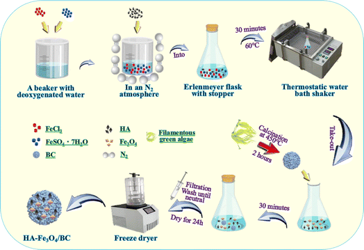
HA–Fe3O4/BC was synthesized according to a previous study using the co-precipitation method.33,44 Briefly, 2.78 g of FeSO4·7H2O and 1.62 g of FeCl3 were added to 250 mL of the conical flask with a stopper and dissolved with 100 mL of deoxygenated water. The deionized water was deoxygenated for 10 min by heating to a temperature of 100 °C. Then, 1.0 g of HA was rapidly added to the mixture solution under a N2 atmosphere. Next, they were stirred and placed at 60 °C for 30 min under a thermostat water bath. Subsequently, 5.0 g of biochar from the filamentous green algae was added to the mixture solution. After 30 min, the precipitated composites were collected, filtered, washed with deionized water until neutral, and freeze-dried for 24 h. Finally, the composites of HA–Fe3O4/BC were obtained. The synthesis procedure of HA–Fe3O4/BC composites is displayed in Fig. 1.2.3 Adsorption experiments
The adsorption of U(VI) removal by HA–Fe3O4/BC was tested through a series of batch experiments. 10 mg of HA–Fe3O4/BC was added into a 250 mL Erlenmeyer flask. Then, 100 mL of U(VI) solution was put into the Erlenmeyer flask. Then, it was placed in a water bath shaker. The reaction conditions, such as pH in solution, reaction time, reaction temperature and the initial concentration of U(VI), could be fixed. After the reaction reached equilibrium, the adsorption experiment was completed. The concentration of U(VI) in the solution was measured by Arsenazo-III colorimetry using a UV-vis spectrophotometer at 650 nm.37 Each adsorption experiment was tested three times under the same reaction conditions. The results are taken as the arithmetic mean.2.4 Characterization
Samples were characterized by technologies of SEM, TEM, FT-IR, XRD and XPS. The detailed information is shown in ESI.†3 Results and discussion
3.1 Characterization of BC and HA–Fe3O4/BC
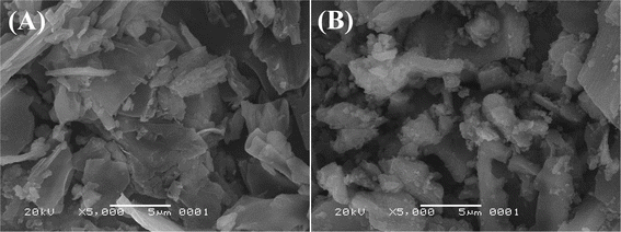
The results of the SEM images were used to characterize the surface morphology of BC (the original biochar) and HA–Fe3O4/BC (the modified biochar with the composites of HA and Fe3O4 nanoparticles). The SEM images of BC and HA–Fe3O4/BC are displayed in Fig. 2.Comparing the surface morphology of BC (Fig. 2A) and HA–Fe3O4/BC (Fig. 2B), the difference in surface morphology could be observed. After modification with the composites of the HA and Fe3O4 nanoparticles, the basic surface structure of biochar was not destroyed compared to the unmodified biochar. From Fig. 2A, it could be observed that BC was an irregular and smooth surface. However, the surface of HA–Fe3O4/BC became rougher and had an irregular surface structure. Some flocculent particles appeared on the surface of HA–Fe3O4/BC. The appearance of these flocculent particles indicated that they might be the composites of HA and Fe3O4 nanoparticles. To further verify these flocculent particles, the characterization of BC and HA–Fe3O4/BC was determined by these technologies of FT-IR, XRD and XPS. The related results are displayed in Fig. 3.
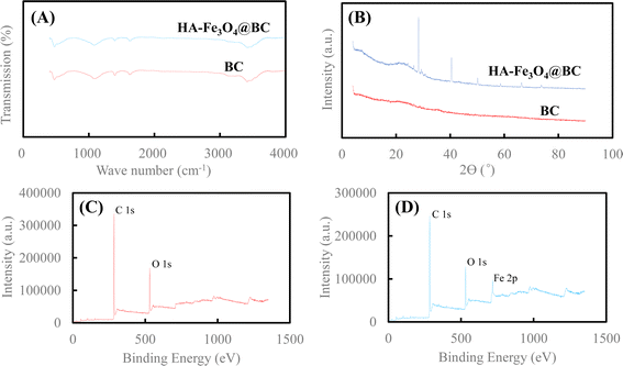 | ||
| Fig. 3 (A) FT-IR spectra of BC and HA–Fe3O4/BC, (B) XRD patterns of BC and HA–Fe3O4/BC, (C) XPS spectra of BC and (D) XPS spectra of HA–Fe3O4/BC. | ||
The surface functional groups of BC and HA–Fe3O4/BC were compared through the FT-IR spectra (Fig. 3A). For BC, the peak at 3404 cm−1 appeared, and it was ascribed to the group of –O–H stretching vibration. This indicates that hydroxyl groups on the surface of BC were observed.45 The two peaks at 1610 cm−1 and 1383 cm−1 of BC represented –C![[double bond, length as m-dash]](https://www.rsc.org/images/entities/char_e001.gif) C– and –CH3 or –CH3 functional groups, respectively.46 The peak at 1060 cm−1 appeared, and it was ascribed to the group of –C–O–C– stretching vibration.47 For HA–Fe3O4/BC, the peaks at 3410 cm−1, 1608 cm−1, 1381 cm−1, and 1053 cm−1 appeared, and they represent –O–H stretching vibration, –C
C– and –CH3 or –CH3 functional groups, respectively.46 The peak at 1060 cm−1 appeared, and it was ascribed to the group of –C–O–C– stretching vibration.47 For HA–Fe3O4/BC, the peaks at 3410 cm−1, 1608 cm−1, 1381 cm−1, and 1053 cm−1 appeared, and they represent –O–H stretching vibration, –C![[double bond, length as m-dash]](https://www.rsc.org/images/entities/char_e001.gif) C– stretching vibration, –CH3 stretching vibration and –C–O–C– stretching vibration, respectively. Additionally, the peak of HA–Fe3O4/BC at 467 cm−1 was assigned to the stretching vibration of Fe–O functional group.48
C– stretching vibration, –CH3 stretching vibration and –C–O–C– stretching vibration, respectively. Additionally, the peak of HA–Fe3O4/BC at 467 cm−1 was assigned to the stretching vibration of Fe–O functional group.48
The crystal phase and structural information of BC and HA–Fe3O4/BC were analyzed according to the results of the XRD pattern. The XRD patterns of BC and HA–Fe3O4/BC are displayed in Fig. 3B. As shown in Fig. 3B, six reflections are at 2θ = 74.06, 66.38, 58.84, 50.12, 40.52 and 28.31°. PDF card no. 96-900-5840 indexed to the magnetite lattice planes are (220), (311), (400), (511), and (440).49 They presented strong signals of Fe3O4 nanoparticles. Therefore, they also indicated the successful coating of Fe3O4 nanoparticles onto BC.
The changes in functional groups on BC and HA–Fe3O4/BC were elaborated through the results of XPS spectra (Fig. 3C and D). From Fig. 3C, the two wide photoelectron lines at the binding energies at 284.06 and 531.06 eV appeared, and they were attributed to C 1s and O 1s, respectively. The main element components of HA–Fe3O4/BC composites were C (76.84% (wt%)) and O (23.16% (wt%)). As shown in Fig. 3D, the three wide photoelectron lines at the binding energies at 284.06, 531.06 and 710.28 eV appeared, and they were attributed to C 1s, O 1s and Fe 2p, respectively. The main element components of HA–Fe3O4/BC composites were C (76.84% (wt%)), O (17.72% (wt%)) and Fe (5.44% (wt%)). The occurrence of the Fe 2p peak (at 710.28 eV) for HA–Fe3O4/BC demonstrated the element of Fe loading onto BC. In other words, the composites of HA–Fe3O4/BC were successfully fabricated by introducing the composites of humic acid-coated Fe3O4 nanoparticles onto the biochar from filamentous green algae using the co-precipitation method.
3.2 Adsorption experiments
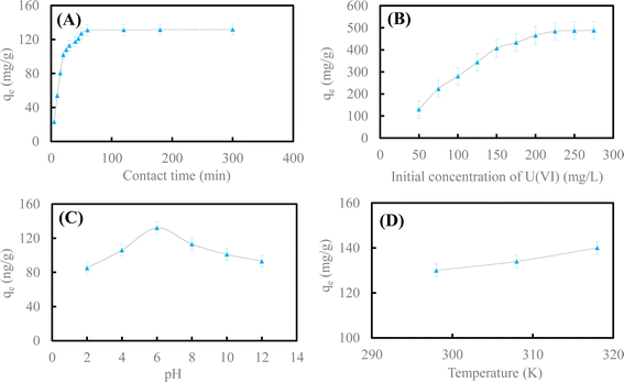 | ||
| Fig. 4 Effect of contact time (A) and initial concentration of U(VI) (B); pH (C) and reaction temperature (D) on U(VI) removal by HA–Fe3O4/BC. | ||
Fig. 4A illustrates the influence of contact time on U(VI) removal by HA–Fe3O4/BC. This adsorption experiment was carried out at different reaction times (t = 5–300 min). The other reaction conditions were as follows: initial concentration of U(VI) was 50 mg L−1, the dosage of HA–Fe3O4/BC was 0.3 g L−1, pH in solution was 6.0 and reaction temperature was 298 K. As exhibited in Fig. 4A, the adsorption process could be divided into two stages. In the first adsorption stage, the removal rate of U(VI) by HA–Fe3O4/BC increased quickly as the reaction time increased. The adsorption capacity of U(VI) by HA–Fe3O4/BC reached 127.2 mg g−1 at a reaction time of 60 min. In the second adsorption stage, the removal rate of U(VI) by HA–Fe3O4/BC increased slowly and reached equilibrium. At this adsorption stage, the adsorption capacity of U(VI) by HA–Fe3O4/BC only increased by 4.56 mg g−1. The removal rate of U(VI) by HA–Fe3O4/BC increased slowly. A large number of adsorption sites on the surface of HA–Fe3O4/BC appeared at the first adsorption stage. They could be conducive to more U(VI) on the surface of HA–Fe3O4/BC. With an increase in reaction time, the adsorption sites on the surface of HA–Fe3O4/BC started to decrease gradually. They were slowly covered by U(VI), and the adsorption processes gradually reached equilibrium.1
Fig. 4B depicts the influence of the initial concentration of U(VI) on U(VI) removal by HA–Fe3O4/BC. The adsorption experiments were carried out at different initial concentrations of U(VI) (C0 = 50–275 mg L−1). The other reaction conditions were as follows: the dosage of HA–Fe3O4/BC was 0.3 g L−1, reaction time was 300 min, pH in solution was 6.0 and reaction temperature was 298 K. As shown in Fig. 4B, the removal capacity of U(VI) by HA–Fe3O4/BC increased slowly with the increase in the initial concentration of U(VI) in the solution. This indicated that the initial concentration of U(VI) had an important influence on the removal capacity, and a high initial concentration of U(VI) would improve the removal capacity of U(VI). This is due to the interaction between U(VI) ions from the solution and the adsorbent. When the initial concentration of U(VI) ions from the solution increased, the driving force of the solution mass on the surface of BC and HA–Fe3O4/BC increased. Therefore, the adsorption capacity increased with an increase in the initial concentration.
Fig. 4C shows the influence of pH in solution on U(VI) removal by HA–Fe3O4/BC. The adsorption experiments were carried out at a different initial pH (pH = 2.0–12.0) adjusted with (1 + 1) H2SO4 and 10% NaOH solution. The other reaction conditions were as follows: the dosage of HA–Fe3O4/BC was 0.3 g L−1, the reaction time was 300 min, the initial concentration of U(VI) was 50 mg L−1 and the reaction temperature was 298 K. As shown in Fig. 4C, the removal capacity of U(VI) by HA–Fe3O4/BC increased gradually at pH ranging from 2.0 to 6.0. Then, it started to decrease slowly at pH ranging from 6.0 to 12.0. The species of U(VI) under a different pH in solution had an important influence on the removal capacity of U(VI) by HA–Fe3O4/BC. At pH < 4.0, the species of U(VI) in solution were mainly UO22+. At pH ranging from 4.0–8.0, the species of U(VI) in solution were (UO2)3(OH)5+ and UO2OH+. At pH > 8.0, the species of U(VI) in solution were (UO2)3(OH)7− and UO2(OH)3−. Therefore, the positively and negatively charged HA–Fe3O4/BC appeared at pH 8.0. The removal capacity of U(VI) was possibly ascribed to the electrostatic interaction between the negative surface charges of HA–Fe3O4/BC and the positive species of U(VI) in the solution. The negatively charged surface of HA–Fe3O4/BC with abundant binding sites increased as the pH in the solution increased. This result is similar to those of previous studies.3,50
Fig. 4D depicts the influence of reaction temperature on U(VI) removal by HA–Fe3O4/BC. The adsorption experiments were carried out at different reaction temperatures (T = 298 K, 308 K and 318 K). The other reaction conditions were as follows: the dosage of HA–Fe3O4/BC was 0.3 g L−1, the reaction time was 300 min, the initial concentration of U(VI) was 50 mg L−1 and the pH in solution was 6.0. As shown in Fig. 4D, the removal capacity of U(VI) by HA–Fe3O4/BC increased as the reaction temperature increased. When the reaction temperature rose from 298 K to 318 K, the value of removal capacity increased from 129.16 mg g−1 to 141.23 mg g−1. This indicated that the reaction temperature affected the diffusion of U(VI) in the solution. The reaction temperature could increase the rate of mass transfer from the bulk to the boundary layer surrounding the surface of HA–Fe3O4/BC.
| qt = qe(1 − e−K1t), | (1) |
 | (2) |
 | (3) |
| qe = KfCe1/n. | (4) |
According to the data of Fig. 4A and B and eqn (1)–(4), adsorption kinetics and adsorption isotherms of U(VI) removal by HA–Fe3O4/BC are displayed in Fig. 5.
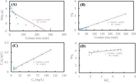 | ||
| Fig. 5 Adsorption kinetics and adsorption isotherms of U(VI) removal by HA–Fe3O4/BC (pseudo-first-order model (A), pseudo-second-order model (B), Langmuir model (C) and Freundlich model (D)). | ||
As shown in Fig. 5A and B, the pseudo-second-order kinetic model could better illustrate the adsorption process of U(VI) on the surface of HA–Fe3O4/BC (R2 = 0.9952 > 0.7351). The values of pseudo-second-order kinetics were close to the results of the adsorption experiment. This implies that the adsorption processes of U(VI) on the surface of HA–Fe3O4/BC were mainly chemisorption.1 As displayed in Fig. 5C and D, the Langmuir model was more consistent with the adsorption process of U(VI) on the surface of HA–Fe3O4/BC than the Freundlich model (R2 = 0.9831 > 0.6468). This indicates that the adsorption process of U(VI) on the surface of HA–Fe3O4/BC was dominated by monolayer adsorption. According to the Langmuir model, the maximum adsorption capacity of U(VI) by HA–Fe3O4/BC could be calculated, and it could reach 555.56 mg g−1. Compared with the related reported, HA–Fe3O4/BC exhibited excellent adsorption performance of U(VI) removal, low cost and wide source. This indicates that these materials of HA–Fe3O4/BC could be widely used in the treatment of U(VI) wastewater.
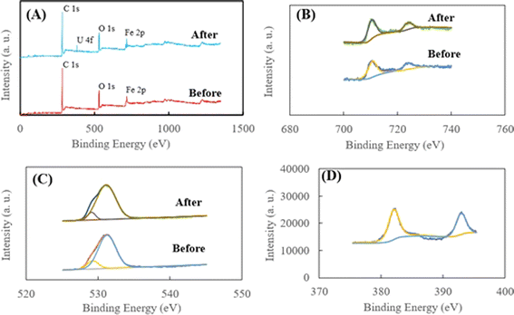
As shown in Fig. 6A, for HA–Fe3O4/BC before the adsorption, the peaks at 283.77, 525.18 and 700.18 eV could be attributed to C 1s, O 1s and Fe 2p, respectively. The appearance of Fe 2p implies that the BC nanoparticles were successfully modified by Fe3O4 nanoparticles. For HA–Fe3O4/BC after the adsorption of U(VI) removal, three peaks of C 1s, O 1s and Fe 2p could be observed. Additionally, the peaks at 382.08 eV could be attributed to U 4f. The appearance of the U 4f peak indicated that U(VI) could be successfully captured on the surface of HA–Fe3O4/BC. As illustrated in Fig. 6B, the two peaks at 711.18 and 725.38 eV. They were assigned to Fe 2p3/2 and Fe 2p1/2, respectively.55 This also indicates that Fe3O4 nanoparticles appeared on the surface of HA–Fe3O4/BC. In addition, the peak areas of Fe 2p3/2 and Fe 2p1/2 changed after adsorption of U(VI), which demonstrates that U(VI) could be reduced to U(IV) by Fe2+.
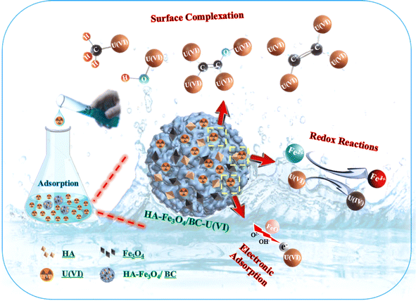
This result is consistent with that illustrated in Fig. 6D. From Fig. 6D, the two peaks at 382.35 and 393.15 eV appeared. They were assigned to U 4f5/2 and U 4f7/2, respectively. They could be deconvoluted into U(IV) and U(VI) sub-peaks. This implies that the reduction reaction of U(VI) with Fe3O4 nanoparticles occurred on the surface of HA–Fe3O4/BC. The O 1s XPS spectra before and after U(VI) removal are shown in Fig. 6C. They could be resolved into two peaks occurring at 531.94 and 534.13 eV, which were ascribed to anionic oxygen and OH− functional groups on the surface of HA–Fe3O4/BC,56 respectively. The relative proportions of the anionic oxygen and OH− functional groups decreased after U(VI) removal. They indicated that anionic oxygen and OH− functional groups played an important role in the U(VI) removal on the surface of HA–Fe3O4/BC. The electrostatic adsorption of anionic oxygen and OH− functional groups with U(VI) was mainly a reaction process of U(VI) removal onto the HA–Fe3O4/BC. Additionally, according to the results of the FT-IR spectra, the number of functional groups (such as –O–H, –C![[double bond, length as m-dash]](https://www.rsc.org/images/entities/char_e001.gif) C–, –CH3 or –CH3, –C–O–C– and Fe–O) could be observed on the surface of HA–Fe3O4/BC. They could adsorb U(VI) through inner-sphere surface complexation. Further, the probable mechanism of U(VI) removal by HA–Fe3O4/BC is illustrated in Fig. 7. This suggests that the probable mechanism of U(VI) removal by HA–Fe3O4/BC could be divided into reduction reaction, inner-sphere surface complexation and electrostatic adsorption.
C–, –CH3 or –CH3, –C–O–C– and Fe–O) could be observed on the surface of HA–Fe3O4/BC. They could adsorb U(VI) through inner-sphere surface complexation. Further, the probable mechanism of U(VI) removal by HA–Fe3O4/BC is illustrated in Fig. 7. This suggests that the probable mechanism of U(VI) removal by HA–Fe3O4/BC could be divided into reduction reaction, inner-sphere surface complexation and electrostatic adsorption.
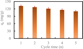
With the increase in the number of cycles, the removal capacity of U(VI) by HA–Fe3O4/BC still could reach 110.82 mg g−1 after five cycles. This exhibited high stability and reusability.
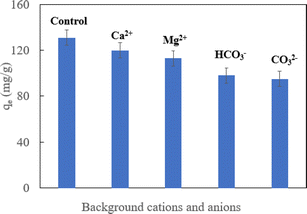
The real ground water samples contained various background ions. They could impact the performance of the adsorbent for pollutant removal. Therefore, the impact of background cations (Mg2+ and Ca2+) and anions (HCO3−, and CO32−) on HA–Fe3O4/BC removal was assessed. As shown in Fig. 9, when each of Mg2+, Ca2+, HCO3−, and CO32− separately existed in solution, they had an important influence on the U(VI) removal by HA–Fe3O4/BC. This might be because adsorption sites on the surface of HA–Fe3O4/BC were occupied by background cations and anions (Mg2+, Ca2+, HCO3−, and CO32−), thus decreasing the adsorption sites.
4 Conclusions
Herein, HA–Fe3O4/BC was fabricated using the co-precipitation method to remove U(VI) from the aqueous solution. Adsorption experiments indicated that HA–Fe3O4/BC exhibited excellent adsorption performance for U(VI) removal, low cost and wide source. The reaction conditions had an important influence on U(VI) removal by HA–Fe3O4/BC. The adsorption processes were dominated by chemisorption and monolayer adsorption. The maximum adsorption capacity of U(VI) by HA–Fe3O4/BC could reach 555.56 mg g−1. The probable mechanisms of U(VI) removal by HA–Fe3O4/BC were reduction reaction, inner-sphere surface complexation and electrostatic adsorption. It is a promising adsorption material for U(VI) removal.Data availability
The data and materials presented in this study are available on request from the corresponding author. The data are not publicly available due to privacy restrictions.Conflicts of interest
There are no conflicts of interest to declare.Acknowledgements
The authors would like to thank their respective institutes for their support in this research.References
- T. Ye, B. Huang, Y. Wang, L. Zhou and Z. Liu, Rapid removal of uranium(VI) using functionalized luffa rattan biochar from aqueous solution, Colloids Surf., A, 2020, 606, 125480 CrossRef CAS.
- A. Corner, D. Venables, A. Spence, W. Poortinga, C. Demski and N. Pidgeon, Nuclear power, climate change and energy security: exploring British public attitudes, Energy Policy, 2011, 39, 4823–4833 CrossRef.
- M. Sobczyk, C. Nguyen Dinh, M. Marzec, E. Bazarkina, K. O. Kvashnina, A. Cwanek, E. Lokas and T. Bajda, Insights into uranium sequestration by coal fly-ash-derived zeolites: Understanding via wet chemistry, and advanced spectroscopies, J. Cleaner Prod., 2024, 449, 141206 CrossRef CAS.
- D. Li and D. I. Kaplan, Sorption coefficients and molecular mechanisms of Pu, U, Np, Am and Tc to Fe (hydr)oxides: a review, J. Hazard. Mater., 2012, 243, 1–18 CrossRef CAS PubMed.
- A. Gladysz-Plaska, E. Grabias and M. Majdan, Simultaneous adsorption of uranium(VI) and phosphate on red clay, Prog. Nucl. Energy, 2018, 104, 150–159 CrossRef CAS.
- S. Avasarala, P. C. Lichtner, A. M. S. Ali, R. González-Pinzón, J. M. Blake and J. M. Cerrato, Reactive transport of U and V from abandoned uranium mine wastes, Environ. Sci. Technol., 2017, 51, 12385–12393 CrossRef CAS.
- H. Liu, M. Li, T. Chen, C. Chen, N. S. Alharbi, T. Hayat, D. Cheng, Q. Zhang and Y. Sun, New synthesis of nZVI/C composites as an efficient adsorbent for the uptake of U(VI) from aqueous solutions, Environ. Sci. Technol., 2017, 51, 9227–9234 CrossRef CAS PubMed.
- B. Bajwa, S. Kumar, S. Singh, S. Sahoo and R. Tripathi, Uranium and other heavy toxic elements distribution in the drinking water samples of SW-Punjab, India, J. Radiat. Res. Appl. Sci., 2017, 10, 13–19 CAS.
- L. Corlin, T. Rock, J. Cordova, M. Woodin, J. L. Durant, D. M. Gute, J. Ingram and D. Brugge, Health effects and environmental justice concerns of exposure to uranium in drinking water, Curr. Environ. Health Rep., 2016, 3, 434–442 CrossRef CAS PubMed.
- M. Qiu, L. Liu, Q. Ling, Y. Cai, S. Yu, S. Wang, D. Fu, B. Hu and X. Wang, Biochar for the removal of contaminants from soil and water: a review, Biochar, 2022, 4, 19 CrossRef CAS.
- S. Yu, H. Tang, D. Zhang, S. Wang, M. Qiu, G. Song, D. Fu, B. Hu and X. Wang, MXenes as emerging nanomaterials in water purification and environmental remediation, Sci. Total Environ., 2022, 811, 152280 CrossRef CAS.
- A. Elzoghby, H. Fahmy, M. Taha and S. Ibrahim, Active carbon-based waste packaging materials for uranium sorption from aqueous solution, Environ. Sci. Pollut. Res., 2023, 30, 74726–74741 CrossRef CAS PubMed.
- J. T. Amphlett, M. D. Ogden, R. I. Foster, N. Syna, K. H. Soldenhoff and C. A. Sharrad, The effect of contaminants on the application of polyamine functionalised ion exchange resins for uranium extraction from sulfate based mining process waters, Chem. Eng. J., 2018, 354, 633–640 CrossRef CAS.
- K. Kiegiel, A. Abramowska, P. Biełuszka, G. Zakrzewska-Kołtuniewicz and S. Wołkowicz, Solvent extraction of uranium from leach solutions obtained in processing of Polish low-grade ores, J. Radioanal. Nucl. Chem., 2017, 311, 589–598 CrossRef CAS PubMed.
- M. Chaudhary, L. Singh, P. Rekha, V. C. Srivastava and P. Mohanty, Adsorption of uranium from aqueous solution as well as seawater conditions by nitrogen-enriched nanoporous polytriazine, Chem. Eng. J., 2019, 378, 122236 CrossRef CAS.
- T. A. Duster, J. E. S. Szymanowski and J. B. Fein, Experimental measurements and surface complexation modeling of U(VI) adsorption onto multilayered graphene oxide: the importance of adsorbate–adsorbent ratios, Environ. Sci. Technol., 2017, 51, 8510–8518 CrossRef CAS PubMed.
- J. T. M. Amphlett, M. D. Ogden, R. I. Foster, N. Syna, K. Soldenhoff and C. A. Sharrad, Polyamine functionalised ion exchange resins: synthesis, characterisation and uranyl uptake, Chem. Eng. J., 2018, 334, 1361–1370 CrossRef CAS.
- A. Sklodowska, S. Mielnicki and L. Drewniak, Raoultella sp. SM1, a novel ironreducing and uranium-precipitating strain, Chemosphere, 2018, 195, 722–726 CrossRef CAS PubMed.
- T. H. Dao, N. T. Nguyen, M. N. Nguyen, C. L. Ngo, N. H. Luong, D. B. Le and T. D. Pham, Adsorption Behavior of Polyelectrolyte onto Alumina and Application in Ciprofloxacin Removal, Polymers, 2020, 12, 1554 CrossRef CAS.
- T. Nguyen, Q. Truong, C. Chen, W. Chen and C. Dong, Pyrolysis of marine algae for biochar production for adsorption of Ciprofloxacin from aqueous solutions, Bioresour. Technol., 2022, 351, 127043 CrossRef CAS.
- K. Ioannou, P. Hadjiyiannis, I. Liatsou and I. Pashalidis, U(VI) adsorption by biochar fiber-MnO2 composites, J. Radioanal. Nucl. Chem., 2019, 320, 425–432 CrossRef CAS.
- L. Gao, L. Peng, J. Li, W. Zhang and B. Shi, Superefficient separation of Th(IV) and U(VI) by lignin-derived magnetic biochar via competitive adsorption mechanism, Sep. Purif. Technol., 2023, 315, 123635 CrossRef.
- E. M. Bakhsh, S. B. Khan, K. Akhtar, E. Y. Danish, T. M. Fagieh, C. Qiu, Y. Sun, V. Romanovski and X. Su, Simultaneous preparation of humic acid and mesoporous silica from municipal sludge and their adsorption properties for U(VI), Colloids Surf., A, 2022, 647, 129060 CrossRef CAS.
- T. Atugoda, C. Gunawardane, M. Ahmad and M. Vithanage, Mechanistic interaction of ciprofloxacin on zeolite modified seaweed (Sargassum crassifolium) derived biochar: Kinetics, isotherm and thermodynamics, Chemosphere, 2021, 281, 130676 CrossRef CAS PubMed.
- S. Bakshi, D. A. Laird, R. G. Smith and R. C. Brown, Capture and Release of Orthophosphate by Fe-Modified Biochars: Mechanisms and Environmental Applications, ACS Sustain. Chem. Eng., 2021, 9, 658–668 CrossRef CAS.
- J. He, Y. Xiao, J. Tang, H. Chen and H. Sun, Persulfate activation with sawdust biochar in aqueous solution by enhanced electron donor-transfer effect, Sci. Total Environ., 2019, 690, 768–777 CrossRef CAS.
- A. Gopinath, G. Divyapriya, V. Srivastava, A. R. Laiju, P. V. Nidheesh and M. S. Kumar, Conversion of sewage sludge into biochar: A potential resource in water and wastewater treatment, Environ. Res., 2021, 194, 110656 CrossRef CAS PubMed.
- V. Dhanya and N. Rajesh, A cradle to approach towards remediation of uranium from water using carbonized arecanut hask fiber, RSC Adv., 2023, 13, 4394–4406 RSC.
- K. M. Poo, E. B. Son, J. S. Chang, X. Ren, Y. J. Choi and K. J. Chae, Biochars derived from wasted marine macro-algae (Saccharina japonica and Sargassum fusiforme) and their potential for heavy metal removal in aqueous solution, J. Environ. Manage., 2018, 206, 364–372 CrossRef CAS.
- M. J. Ahmed, P. U. Okoye, E. H. Hummadi and B. H. Hameed, High-performance porous biochar from the pyrolysis of natural and renewable seaweed (Gelidiella acerosa) and its application for the adsorption of methylene blue, Bioresour. Technol., 2019, 278, 159–164 CrossRef CAS.
- X. Yao, L. Ji, J. Guo, S. Ge, W. Lu, L. Cai, Y. Wang, W. Song and H. Zhang, Magnetic activated biochar nanocomposites derived from wakame and its application in methylene blue adsorption, Bioresour. Technol., 2020, 302, 122842 CrossRef CAS PubMed.
- Y. Han, X. Cao, X. Ouyang, S. P. Sohi and J. Chen, Adsorption kinetics of magnetic biochar derived from peanut hull on removal of Cr (VI) from aqueous solution: effects of production conditions and particle size, Chemosphere, 2016, 145, 336–341 CrossRef CAS.
- K. R. Thines, E. C. Abdullah, N. M. Mubarak and M. Ruthiraan, Synthesis of magnetic biochar from agricultural waste biomass to enhancing route for waste water and polymer application: a review, Renewable Sustainable Energy Rev., 2017, 67, 257–276 CrossRef CAS.
- F. Huber, D. Schild, T. Vitova, J. Rothe, R. Kirsch and T. Schafer, U(VI) removal kinetics in presence of synthetic magnetite nanoparticles, Geochim. Cosmochim. Acta, 2012, 96, 154–173 CrossRef CAS.
- Y. Xie, C. Chen, X. Ren, X. Wang, H. Wang and X. Wang, Emerging natural and tailored materials for uranium-contaminated water treatment and environmental remediation, Prog. Mater. Sci., 2019, 103, 180–234 CrossRef CAS.
- X. J. Jin, R. R. Liu, H. F. Wang, L. Han, M. Q. Qiu and B. W. Hu, Functionalized porous nanoscale Fe3O4 particles supported biochar from peanut shell for Pb(II) ions removal from landscape wastewater, Environ. Sci. Pollut. Res., 2022, 29, 37159–37169 CrossRef CAS PubMed.
- Y. Zhang, Y. Li, Y. Ning, D. Liu, P. Tang, Z. Yang, Y. Lu and X. Wang, Adsorption and desorption of uranium (VI) onto humic acids derived from uranium-enriched lignites, Water Sci. Technol., 2018, 77, 920–930 CrossRef CAS PubMed.
- L. Yao, H. Yang, Z. Chen, M. Qiu, B. Hu and X. Wang, Bismuth oxychloride-based materials for the removal of organic pollutants in wastewater, Chemosphere, 2021, 273, 128576 CrossRef CAS.
- D. Maity and D. C. Agrawal, Synthesis of iron oxide nanoparticles under oxidizing environment and their stabilization in aqueous and non-aqueous media, J. Magn. Magn. Mater., 2007, 308, 46–55 CrossRef CAS.
- W. Li, J. T. Mayo, D. N. Benoit, L. D. Troyer, Z. A. Lewicka, B. J. Lafferty, J. G. Catalano, S. S. Lee, V. L. Colvin and J. D. Fortner, Engineered superparamagnetic iron oxide nanoparticles for ultra-enhanced uranium separation and sensing, J. Mater. Chem. A, 2016, 4, 15022–15029 RSC.
- H. Gonzalez-Raymat, V. Anagnostopoulos, M. Denham, Y. Cai and Y. P. Katsenovich, Unrefined humic substances as a potential low-cost amendment for the management of acidic groundwater contamination, J. Environ. Manage., 2018, 212, 210–218 CrossRef CAS.
- S. Yang, P. Zong, X. Ren, Q. Wang and X. Wang, Rapid and highly efficient preconcentration of Eu(III) by core-shell structured Fe3O4@humic acid magnetic nanoparticles, ACS Appl. Mater. Interfaces, 2012, 4, 6891–6900 CrossRef CAS.
- P. Singhal, S. K. Jha, S. P. Pandey and S. Neogy, Rapid extraction of uranium from sea water using Fe3O4 and humic acid coated Fe3O4 nanoparticles, J. Hazard. Mater., 2017, 335, 152–161 CrossRef CAS PubMed.
- W. Jiang, Q. Cai, W. Xu, M. Yang, Y. Cai and D. D. Dionysiou, et al., Cr(VI) adsorption and reduction by humic acid coated on magnetite, Environ. Sci. Technol., 2014, 48, 8078–8085 CrossRef CAS PubMed.
- H. Wang, H. Wang, H. Zhao and Q. Yan, Adsorption and Fenton-like removal of chelated nickel from Zn-Ni alloy electroplating wastewater using activated biochar composite derived from Taihu blue algae, Chem. Eng. J., 2020, 379, 122372 CrossRef CAS.
- F. Xiao, J. Cheng, W. Cao, C. Yang, J. Chen and Z. Luo, Removal of heavy metals from aqueous solution using chitosan-combined magnetic biochars, J. Colloid Interface Sci., 2019, 540, 579–584 CrossRef CAS.
- D. Cheng, H. H. Ngo, W. Guo, S. W. Chang, D. D. Nguyen and X. Zhang, et al., Feasibility study on a new pomelo peel derived biochar for tetracycline antibiotics removal in swine wastewater, Sci. Total Environ., 2020, 720, 137662 CrossRef CAS PubMed.
- C. Shan, Z. Ma and M. Tong, Efficient removal of trace antimony(III) through adsorption by hematite modified magnetic nanoparticles, J. Hazard. Mater., 2014, 268, 229–236 CrossRef CAS PubMed.
- M. Li, H. Liu, T. Chen and W. Lin, Nano-hematite prepared by activation of natural siderite and its performance on immobilization of Eu(III), Appl. Geochem., 2017, 84, 154–161 CrossRef CAS.
- C. Ding, W. Cheng, Y. Sun and X. Wang, Effects of Bacillus subtilis on the reduction of U(VI) by nano-Fe0, Geochim. Cosmochim. Acta, 2015, 165, 86–107 CrossRef CAS.
- S. Lagergren, Zur theorie der sogenannten adsorption geloster stoffe Pseudo-second order model for sorption processes, Handlingar, 1898, 24, 1–39 Search PubMed.
- H. M. F. Freundlich, Uber die adsorption in lasungen, J. Phys. Chem., 1906, 57, 385–470 CAS.
- I. Langmuir, The adsorption of gases on plane surface of glass, mica and platinum, J. Am. Chem. Soc., 1918, 40, 1361–1403 CrossRef CAS.
- W. S. Hummers and R. E. Offeman, Preparation of graphitic oxide, J. Am. Chem. Soc., 1958, 80, 1339 CrossRef CAS.
- C. Galindo, M. Del Nero, R. Barillon, E. Halter and B. Made, Mechanisms of uranyl and phosphate (co)sorption: complexation and precipitation at alpha-Al2O3 surfaces, J. Colloid Interface Sci., 2010, 347, 282–289 CrossRef CAS.
- C. Ding, W. Cheng, X. Nie and F. Yi, Synergistic mechanism of U(VI) sequestration by magnetite-graphene oxide composites: evidence from spectroscopic and theoretical calculation, Chem. Eng. J., 2017, 324, 113–121 CrossRef CAS.
Footnote |
| † Electronic supplementary information (ESI) available. See DOI: https://doi.org/10.1039/d4ra03421j |
| This journal is © The Royal Society of Chemistry 2024 |

