 Open Access Article
Polyaniline nanofiber: an excellent anode material for microbial fuel cells
Jalal Ahmed and
Sunghyun Kim *
*
Department of Systems Biotechnology, Konkuk Institute of Science and Technology, Konkuk University, 120 Neudong-ro, Gwangjin-gu, Seoul 05029, Korea. E-mail: skim100@konkuk.ac.kr; Tel: +82 2 450 3378
First published on 29th October 2024
Abstract
Sluggish electron transfer from the bacterial metabolic system to the electrode is a critical issue in microbial fuel cell (MFC) research. However, a number of strategies have already been demonstrated for the improved performance of MFCs through the chemical or electrochemical manipulation of the anode. In this study, a new anode fabrication technique was introduced with polyaniline nanofibers (PANInf) to increase the surface area of the anode in a three-dimensional pattern. A large number of bacteria were anchored to the high surface area anode through the electrostatic interaction between positively charged anode surface and negatively charged bacteria cell wall. An improved conductive nature also plays an important role in accelerating the electron transfer process, yielding a current density of 0.87 mA cm−2, which is almost a 73% increase from that of the PANI anode (0.503 mA cm−2). The maximum power density with a PANInf-modified anode was 1091 ± 5% mW m−2, which is 40% higher than that of the PANI-modified anode (777 ± 5% mW m−2). Impedance spectroscopic study shows that PANInf modification reasonably reduces the charge transfer resistance, leading to faster electron transfer kinetics.
Introduction
Electricity generation in microbial fuel cells (MFCs) through the catalytic degradation of organic components has drawn significant attention in recent years as a carbon-neutral, eco-friendly, and renewable green energy source.1,2 The versatility of microbes in utilizing a diverse range of fuels makes MFCs an ideal technology for applications such as wastewater treatment,3–5 energy recovery,6 and power supply for remote sensing using indigenous fuels.7 Several factors influence MFC performance, including cell design, substrates, flow rate, and temperature.8,9Electrode materials based on carbon are particularly crucial as they considerably enhanced power generation and MFC performance by providing a large surface area to anchor a dense bacterial population, facilitating high substrate oxidation rates and rapid electron transfer to the external circuit.10,11 They exhibit a variety of physical and chemical properties, including differences in bacterial attachment, electron transfer capabilities, internal resistance, and reaction rates on the electrode surface. Various carbon-based materials, such as carbon cloth, carbon paper,12 graphite granules, graphite felt, graphite fiber brushes,13 carbon mesh,14 graphite rods,15 and reticulated vitreous carbon (RVC),16 are extensively utilized as MFC anodes. These materials are favoured for their high chemical stability, biocompatibility, substantial surface area, excellent conductivity, and ability to support bacterial colony formation.
Despite their advantages, carbon materials have considerable drawbacks such as clogging due to cell death, high resistance, fragility, and high costs for field-scale applications.17 Moreover, the inefficiencies of the anodic process on the electrode surface are yet to be fully elucidated. Several strategies have been explored to enhance the electrocatalytic performance of anodes, including the immobilization of redox mediators, which has proven to be effective.18,19 However, the durability of redox mediators is questionable due to their toxicity and tendency to wash off the electrode surface.20
The nanostructural advantages of conductive materials, with their unique electrical and catalytic properties, have been found to significantly improve both bioelectrocatalytic and signal transduction processes, thereby enhancing MFC performance.21 For example, Wu et al.22 demonstrated enhanced electron transfer from Shewanella to a boron-doped diamond nanograss array, improving bacterial interaction with the electrode surface. Studies have explored the potential of carbon nanotube–polymer composites to increase bacterial electron transfer,23–25 although the toxicity of CNTs can lead to cell death and inhibit cell proliferation.
Conductive polymers such as polyaniline and polypyrrole along with their composites continue to be extensively researched for their application in various electrochemical devices due to their conductive properties and polymer structure.26,27 Polyaniline, in particular, is particularly attractive due to its ease of processing, electrical conductivity, and environmental stability. The electronic properties of these polymers can be manipulated through processes such as doping-dedoping and protonation,28 and their reversible redox activity and ability to form ordered nanostructures make them ideal materials for bioelectricity generation systems.29
Recently, there has been considerable attention on enhancing the MFC performance through the additive role of conductive polymers in the anode. Among the conductive polymers studied, polyaniline, polypyrrole (PPy), and their composite materials have been shown to effectively improve MFC performance. Lai et al.30 demonstrated that an anode modified with polyaniline increased the power output to 2.6 times that of an unmodified anode. Feng et al.31 used a copolymer, polypyrrole/anthraquinone-2,6-disulphonic (PPy/AQDS), to modify an anode, achieving a maximum power density 13 times greater than that of an unmodified one. Anodes coated with a nanotube/polyaniline composite demonstrated improved power density in MFCs compared to those coated solely with carbon nanotubes.24 However, the potential issues of carbon nanotube toxicity and biomass deposition clogging, which can hinder substrate diffusion and increase electrode resistance, were not addressed.
In this study, we propose a polyaniline nanofiber (PANInf) composite electrode, which offers higher conductivity and greater affinity for bacterial attachment on the electrode surface, as a promising option for enhancing microbial fuel cell performance. The nano-scale fabrication of the electrode surface with PANInf could facilitate faster electron transfer and more rapid proton release from the dense biofilm. The mesoporous morphology of the nanofiber-modified surface clearly benefits substrate diffusion within the dense biofilm, thereby accelerating the substrate oxidation rate.
Experimental
Chemicals and materials
All chemicals used were of reagent grade and purchased from Sigma-Aldrich; they were utilized as received without further purification. A solution of polytetrafluoroethylene (PTFE) from DuPont was employed to fabricate the gas diffusion layer. 20% platinum on Vulcan X-72 carbon was procured from E-Tek, USA. Non-wet-proofed (type A) and 30% wet-proofed (type B) carbon cloths, supplied by Fuel Cell Earth, USA, served as the anode and cathode materials, respectively. Untreated sludge was collected from the Jung-Nang sewage treatment facility in Seoul, Korea.Polyaniline nanofiber (PANInf) and polyaniline (PANI) synthesis
Before synthesizing PANInf, the aniline monomer was distilled under reduced pressure. Polyaniline nanofiber was synthesized at room temperature from the aqueous/organic interface, as previously described by Huang et al.32 Briefly, a 0.3 M solution of aniline in dichloromethane was covered with a spray of 0.075 M ammonium persulfate in 1 M perchloric acid solution, twice the volume of the aniline solution, and left to react at room temperature for 24 hours. The resultant PANInf was thoroughly washed with copious amounts of deionized water and acetonitrile until the filtrate became colorless. Doping was performed by stirring the PANInf in 1.0 M perchloric acid for 15 hours, followed by filtration, extensive washing with water, and vacuum drying at 40 °C.Conventional polyaniline synthesis was carried out in an ice bath, maintaining the temperature in the range of 0–5 °C. The aniline monomer was added to an ammonium persulfate (0.075 M) solution, stirred vigorously and allowed to settle for 24 h to complete polymerization. The morphologies of the synthesized PANInf and PANI were examined using a SEM instrument (JSM 6380, JEOL, Japan).
Electrode preparation and MFC set up
Air cathodes were prepared as previously described by Cheng et al.33 with a platinum loading of 0.3 mg cm−2. Both 3 mg cm−2 PANInf/PANI and 1 mg cm−2 carbon black (Vulcan XC72) were thoroughly mixed. After thorough mixing, 0.5 mL water and 100 μL of a 5% Nafion solution were added sequentially, followed by sonication for 30 min to ensure the complete dispersion of the nanofibers. This composite mixture was then applied to one side of a type A carbon cloth anode and allowed to dry overnight at room temperature. A cylindrical single-chamber MFC reactor, measuring 3.0 cm in diameter by 2.1 cm in length, was constructed from Plexiglass with an internal volume of 14 mL; the cathode and anode were positioned facing each other with a 2.0 cm gap.Enrichment and operation
MFCs were inoculated by mixing 2 mL of aerobic sludge with culture media. The culture media comprised a 1 g per L acetate solution in a 50 mM phosphate buffer, supplemented with 12.5 mL L−1 of minerals and 5 mL L−1 of vitamins. The MFC operated in the batch mode, connected to a 1 kΩ external resistor. The batch was changed when the cell voltage dropped below 10 mV, using the same culture media. After achieving at least five consecutive and reproducible charging–discharging cycles, the polarization curve was obtained by connecting variable external resistors. The power density curves were derived from the polarization curves as a function of current density using P = IV. Three independent MFCs were simultaneously operated and the average values were taken.Measurements and calculations
The structural conformation of polyaniline and the bacterial biofilm were examined using scanning electron microscopy (SEM, JSM 6380, JEOL Japan) and transmission electron microscopy (TEM, Tecnai G2 F30, FEI, USA). Fixation of the biofilm bacteria was achieved by rinsing the biofilm on carbon cloth in PBS solution three times, followed by a 2 h incubation in 2.5% glutaraldehyde solution; it was then washed with deionized water and sequentially dehydrated through exposure to ethanol solutions of increasing concentrations (10, 25, 50, 75, 90, and 100%) for 20 min each.Cyclic voltammetry was performed on an MFC cell using a saturated calomel electrode (SCE) positioned between the cathode and anode, with the data recorded by a potentiostat (Autolab PGSTAT 30, ECO CHEM). Electrochemical impedance spectroscopy was used to measure the internal resistance (Rint) at an open circuit voltage (OCV) across the frequency range from 10 kHz to 10 mHz applying a sinusoidal perturbation of 10 mV amplitude using the same potentiostat. The total impedance was graphed on the Zre–Zim plane (Nyquist plot) to determine the internal resistance (Rint), and the ohmic resistance (RΩ) and charge-transfer resistance (Rct) components were subsequently derived from the fit data of the impedance plot. The cell voltage (Vcell) over the external resistance (Rext) was recorded over time by an automatic battery cycler (WBCS300, WonAtech, Korea). The plot of power density versus current was constructed from the polarization curve as previously described.34
Results and discussion
Characterization of synthesized PANInf
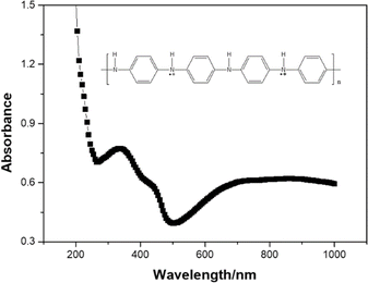
Synthesized PANInf exists in the emeraldine salt form among four different forms of PANI after doping in 1.0 M perchloric acid. It was confirmed by UV/vis absorption spectra (Fig. 1).The structural morphologies of the synthesized PANInf and PANI were observed using scanning electron microscopy, as shown in Fig. 2A and B. PANInf displays a uniform, net-like fibrous structure that interconnects to form a distinct three-dimensional network, enhancing contact with the bacteria. Its porous nature facilitates substrate diffusion within the catalyst layer. The fibres have lengths ranging from several hundred nanometers to several micrometers, with an average diameter of approximately 50 nm, as confirmed by the TEM image (Fig. 2E).
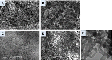 | ||
| Fig. 2 SEM images of PANInf (A) and PANI (B). (C and D) Show SEM images of the bacterial biofilm on the PANInf and PANI, respectively. (E) Shows the TEM image of PANInf. | ||
Note that washing PANInf with acetonitrile increases its conductivity tenfold from the usual scale.35 This increase is attributed to the removal of residual monomeric species adhering to the fibre surface. The 3D spatial conformation of the fibres allows bacteria to colonize deep within the electrode, fostering significant interactions between the anolyte, bacteria, and biofilm.
In contrast, conventional PANI forms thick, coarse particle-shaped networks that offer fewer interspaces, resulting in less pronounced three-dimensional characteristics. Fig. 2C depicts densely populated bacteria on the PANInf-modified surface, indicating a biofilm that diversifies across the PANInf surface, thereby providing additional space for bacterial settlement. This modified surface structurally favours the accommodation of multiple bacterial layers. However, the PANI anode surface, as shown in Fig. 2D, supports a more two-dimensional bacterial population, though both surfaces accumulate positive charges that drive the bacteria towards them. The conductive nature of the nanofibers, coupled with high interaction levels, potentially facilitates faster electron and proton release.
Voltage generation from MFCs with PANInf and PANI anodes, and voltammetric response of anode biofilms
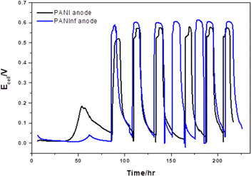
To assess the PANInf and PANI anodes, we operated both microbial fuel cells (MFCs) under identical conditions simultaneously. We monitored the voltage generation including a start-up period, as shown in Fig. 3. Initially, the PANInf-modified anode displayed slower voltage generation compared to the PANI anode. This slower onset can be attributed to the more extended period required for bacteria to inoculate the interior of the PANInf, which offers less room for bacteria compared to the PANI-decorated anode that behaves more like a 2D surface, facilitating straightforward biofilm formation.Over time, the PANInf-modified MFC began producing higher voltages than the PANI-modified MFC. This sustained voltage generation, observed for over ten days, indicates a higher substrate oxidation rate on the nanofiber-decorated anode, resulting in a cell voltage approximately 40 mV higher than that of the conventional PANI-modified electrode. The higher oxidation current observed for the modified anode is a result of the increased substrate oxidation rate and the large number of bacteria colonizing the polyaniline nanofibers surface. Studies such as those by Bond et al.36 and Reguera et al.37 have shown that an increase in biomass attached to the electrode surface enhances the oxidation of electron-donating species as Liu et al.38 established the relationship between current potential and MFC cell performance.
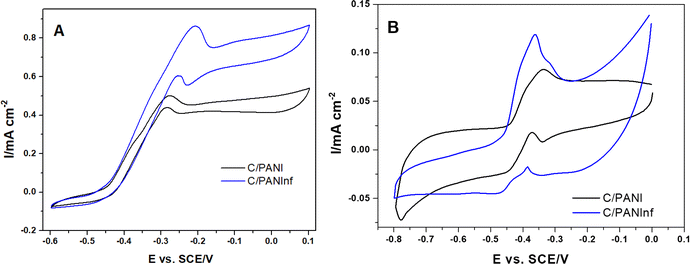
Cyclic voltammetry techniques were used to study and characterize the electron transfer interactions between microorganisms and the anode. Fig. 4A presents a typical voltammogram of a bacterial biofilm, characterized by a sigmoidal shape with a single inflection point. Here, we observed a higher catalytic current of 0.87 mA cm−2 on PANInf modification, compared to only 0.5 mA cm−2 for PANI. This strong correlation with the peak current in substrate-depleted conditions (Fig. 4B) and catalytic currents described by Fricke et al.39 suggest that electron transfer from bacteria to the electrode can occur over a wider redox potential window for PANInf, whereas it is more restricted for PANI.
Structural transformations from benzoid to quinoid forms are more readily facilitated with a positive shift in the voltage on PANInf, as shown by Ding et al.,40 while these transformations in PANI are monotonically restricted, resulting in inferior electron transfer at certain potentials. Hence, PANInf provides a clear advantage over conventional PANI as an anode material.
MFC power generation
Bioelectricity generation in microbial fuel cells (MFCs) is critically dependent on the properties of the anode, which are determined by the materials used. As illustrated in Fig. 5, the power density varies with the current density. According to start-up experiments, the PANInf electrode considerably outperforms the PANI electrode. The power density increases with current density but begins to decline with further increase. This relationship between the output current density and power density is typical. The maximum power density recorded was 1091 ± 5% mW m−2 at a current density of 3.83 A m−2, which is 40% higher than that of the PANI anode, which recorded 777 ± 5% mW m−2 at a current density of 3.36 A m−2.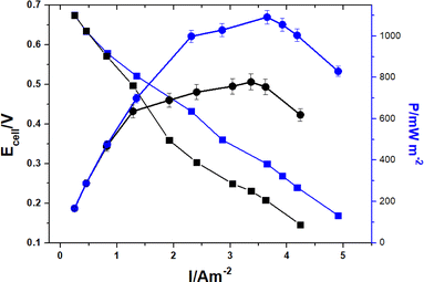 | ||
| Fig. 5 Polarization (■) and power density (●) curves for PANI (black) and PANInf (blue) anodes as a function of current density. | ||
This performance exceeds that of other recent studies, for example, 228 mW m−2 with a polypyrrole carbon nanotubes composite electrode,41 42 mW m−2 with a polyaniline/carbon nanotube composite electrode,24 and 27.4 mW m−2 with a polyaniline and poly(aniline-co-o-aminophenol) modified anode.42
The superior power density of PANInf is attributed to its mesoporous structure and biocompatibility, which offer an optimal habitat for a large bacterial population.
The power density in this study is comparable to that achieved with a three-dimensional loofah-like anode,43 although the anode in this case is two-dimensional. PANInf's high conductivity is crucial for minimizing the overpotential and efficiently delivering electrons to the external circuit. Additionally, the 3D nanofiber network facilitates the diffusion of reactants and products, while a large specific anode surface area enhances the cell potential by reducing activation losses at higher current densities.
Electrochemical impedance study
Electrochemical impedance spectroscopy (EIS) measurements were conducted to compare the charge transfer characteristics of both PANI and PANInf-modified anodes. The charge-transfer resistance (Rct), indicated by the diameter of the semicircle in the high-frequency region of the Nyquist plot (Fig. 6), shows that the Rct for the PANInf-modified anode is approximately 35 Ω, whereas it is about 44 Ω for the PANI-modified anode. A decrease in Rct signifies enhanced electrode processes and superior electron transport capacity due to the highly conductive PANInf on the anode surface. The Rct is influenced by the electrode surface reactions and the charge transfer processes, which depend on the bacterial population and the properties of the electrode surface. Surface kinetics impact the interfacial capacitance, which in turn reduces the Rct and increases the power density. Qiao et al. observed a similar phenomenon with the introduction of conducting polymers in their microbial fuel cells (MFCs), which significantly reduced the Rct of the system (Qiao et al., 2007).24 Thus, a highly conductive surface offers an additional advantage in reducing the internal resistance, a key barrier to achieving higher power generation in MFCs.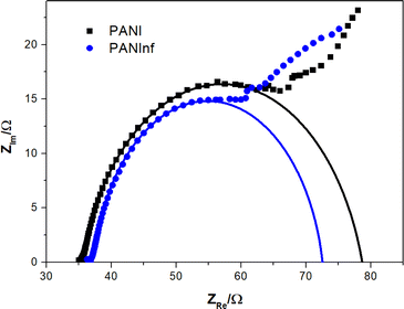 | ||
| Fig. 6 Nyquist plots of PANI (black) and PANInf (blue)-modified anodes measured between 10 kHz and 10 Hz. Black and blue lines are fitted curves for PANI and PANInf anodes, respectively. | ||
Furthermore, a decrease in Rct and an increase in capacitance are also indicative of conducting biofilm formation and bacterial aggregation, as supported by the bacterial distribution within the biofilm shown in Fig. 1C.44
Conclusions
In summary, a highly conductive surface composed of mesoporous polyaniline nanofibers was developed to enhance the performance of microbial fuel cells (MFCs). This innovative anode material facilitates the formation of a dense biofilm, supporting a large population of bacteria. The three-dimensional network of the polyaniline nanofibers (PANInf) interconnects bacteria that are distant from the anode surface, enhancing electron transfer to the electrode. The high dual conductivity of PANInf enables the simultaneous transport of electrons and protons while reducing the surface resistance. This leads to more efficient electrochemical cells and improved power generation.Although MFC technology has not yet been implemented in practical application, our method is expected to be adopted for anode preparation when this technology is commercialized.
Data availability
The data that support the findings of this study are available from the corresponding author upon request.Author contributions
J. Ahmed performed PANInf synthesis and MFC experiments, and wrote the first draft of the manuscript. S. Kim supervised the research and completed the manuscript.Conflicts of interest
There are no conflicts to declare.Acknowledgements
This paper was written as part of Konkuk University's research support program for its faculty on sabbatical leave in 2021.References
- J. V. Boas, V. B. Oliveira, M. Simoes and A. M. F. R. Pinto, J. Environ. Manage., 2022, 307, 114525 CrossRef CAS PubMed.
- R. Prashanthi, Ionics, 2023, 29, 1667–1697 CrossRef CAS.
- G. J. Tsekouras, P. M. Deligianni, F. D. Kanellos, V. T. Kontargyri, P. A. Kontaxis, N. M. Manousakis and C. N. Elias, Front. Energy Res., 2022, 10, 843768 CrossRef.
- C. Abourached, M. J. English and H. Liu, J. Cleaner Prod., 2016, 137, 144–149 CrossRef CAS.
- Y. Guo, J. Wang, S. Shinde, X. Wang, Y. Li, Y. Dai, J. Ren, P. Zhang and X. Liu, RSC Adv., 2020, 10, 25874–25887 RSC.
- M. O. Idris, H.-C. Kim, A. A. Yaqoob and M. N. M. Ibraim, Sustain. Energy Technol. Assessments, 2022, 52, 102183 CrossRef.
- F. Ivars-Barceló, A. Zuliani, M. Fallah, M. Mashkour, M. Rahimnejad and R. Luque, Appl. Sci., 2018, 8, 1184 CrossRef.
- I. Ieropoulos, J. Winfield and J. Greenman, Bioresour. Technol., 2010, 101, 3520–3525 CrossRef CAS PubMed.
- H. Liu, S. A. Cheng and B. E. Logan, Environ. Sci. Technol., 2005, 39, 588–5493 Search PubMed.
- X. Huang, C. Duan, W. Duan, F. Sun, H. Cui, S. Zhang and X. Chen, J. Cleaner Prod., 2021, 201, 126951 CrossRef.
- F. Mahmoodzadeh, N. Navidjouy, S. Alizadeh and M. Rahimnejad, Sci. Rep., 2023, 13, 20755 CrossRef CAS PubMed.
- J. R. Kim, S. H. Jung, J. M. Regan and B. E. Logan, Bioresour. Technol., 2007, 98, 2568–2577 CrossRef CAS PubMed.
- Y. Ahn and B. E. Logan, Bioresour. Technol., 2010, 101, 469–475 CrossRef CAS PubMed.
- Y. Luo, F. Zhang, B. Wei, G. L. Liu, R. D. Zhang and B. E. Logan, J. Power Sources, 2011, 196, 9317–9321 CrossRef CAS.
- B. E. Logan, Water Sci. Technol., 2005, 52, 31–37 CrossRef CAS PubMed.
- Z. He, S. D. Minteer and L. T. Angenent, Environ. Sci. Technol., 2005, 39, 5262–5267 CrossRef CAS PubMed.
- M. H. Zhou, M. L. Chi, J. M. Luo, H. H. He and T. Jin, J. Power Sources, 2011, 196, 4427–4435 CrossRef CAS.
- M. Adachi, T. Shimomura, M. Komatsu, H. Yakuwa and A. Miya, Chem. Commun., 2008, 17, 2055–2057 RSC.
- X. H. Tang, Z. W. Du and H. R. Li, Electrochem. Commun., 2010, 12, 1140–1143 CrossRef CAS.
- D. R. Lovley, Nat. Rev. Microbiol., 2006, 4, 497–508 CrossRef CAS PubMed.
- R. Nakamura, F. Kai, A. Okamoto, G. J. Newton and K. Hashimoto, Angew. Chem., Int. Ed., 2009, 48, 508–511 CrossRef CAS PubMed.
- W. G. Wu, L. L. Bai, X. Liu, Z. M. Tang and Z. Z. Gu, Electrochem. Commun., 2011, 13, 872–874 CrossRef CAS.
- L. Peng, S. J. You and J. Y. Wang, Biosens. Bioelectron., 2010, 25, 1248–1251 CrossRef CAS PubMed.
- Y. Qiao, C. M. Li, S. J. Bao and Q. L. Bao, J. Power Sources, 2007, 170, 79–84 CrossRef CAS.
- X. Xie, L. B. Hu, M. Pasta, G. F. Wells, D. S. Kong, C. S. Criddle and Y. Cui, Nano Lett., 2011, 11, 291–296 CrossRef CAS PubMed.
- H. Dong, C. M. Li, W. Chen, Q. Zhou, Z. X. Zeng and J. H. T. Luong, Anal. Chem., 2006, 78, 7424–7431 CrossRef CAS PubMed.
- C. M. Li, W. Chen, X. Yang, C. Q. Sun, C. Gao, Z. X. Zheng and J. Sawyer, Front. Biosci., 2005, 10, 2518–2526 CrossRef CAS PubMed.
- H. Zengin, W. S. Zhou, J. Y. Jin, R. Czerw, D. W. Smith, L. Echegoyen, D. L. Carroll, S. H. Foulger and J. Ballato, Adv. Mater., 2002, 14, 1480–1483 CrossRef CAS.
- C. M. Ding, H. Liu, Y. Zhu, M. X. Wan and L. Jiang, Energy Environ. Sci., 2012, 5, 8517–8522 RSC.
- B. Lai, X. H. Tang, H. R. Li, Z. W. Du, X. W. Liu and Q. Zhang, Biosens. Bioelectron., 2011, 28, 373–377 CrossRef CAS PubMed.
- C. H. Feng, L. Ma, F. B. Li, H. J. Mai, X. M. Lang and S. S. Fan, Biosens. Bioelectron., 2010, 25, 1516–1520 CrossRef CAS PubMed.
- J. X. Huang, S. Virji, B. H. Weiller and R. B. Kaner, J. Am. Chem. Soc., 2003, 125, 314–315 CrossRef CAS PubMed.
- S. Cheng, H. Liu and B. E. Logan, Electrochem. Commun., 2006, 8, 489–494 CrossRef CAS.
- S. Cheng, H. Liu and B. E. Logan, Environ. Sci. Technol., 2006, 40, 364–369 CrossRef CAS PubMed.
- S. R. Sivakkumar, J. S. Oh and D. W. Kim, J. Power Sources, 2006, 163, 573–577 CrossRef CAS.
- D. R. Bond, D. E. Holmes, L. M. Tender and D. R. Lovely, Science, 2002, 295, 483–485 CrossRef CAS PubMed.
- G. Reguera, K. P. Nevin, J. S. Nicoll, S. F. Covalla, T. L. Woodard, D. R. Lovely and D. R. Appl, Environ. Microbiol., 2006, 72, 7345–7348 CrossRef CAS PubMed.
- H. Liu, S. A. Cheng and B. E. Logan, Environ. Sci. Technol., 2005, 39, 658–662 CrossRef CAS PubMed.
- K. Fricke, F. Harnisch and U. Schröder, Energy Environ. Sci., 2008, 1, 144–147 RSC.
- C. M. Ding, H. Liu, Y. Zhu, M. X. Wan and L. Jiang, Energy Environ. Sci., 2012, 5, 8517–8522 RSC.
- Y. J. Zou, C. L. Xiang, L. N. Yang, L. X. Sun, F. Xu and Z. Cao, Int. J. Hydrogen Energy, 2008, 33, 4856–4862 CrossRef CAS.
- C. Li, L. B. Zhang, L. L. Ding, H. Q. Ren and H. Cui, Biosens. Bioelectron., 2011, 26, 4169–4176 CrossRef CAS PubMed.
- Y. Yuan, S. G. Zhou, Y. Liu and J. H. Tang, Environ. Sci. Technol., 2013, 47, 14525–14532 CrossRef CAS PubMed.
- R. P. Ramasamy, Z. Y. Ren, M. M. Mench and J. M. Regan, Biotechnol. Bioeng., 2008, 101, 101–108 CrossRef CAS PubMed.
| This journal is © The Royal Society of Chemistry 2024 |

