 Open Access Article
Upconverting particles in near-infrared light-induced TiO2 photocatalysis: towards the optimal architecture of upconverter/photocatalyst systems†
Paulina O'Callaghana,
Agnieszka Jarosz-Dudaa,
Joanna Kuncewicz *a,
Krzysztof Dzierżęga
 b and
Wojciech Macyk
 *a
*a
aFaculty of Chemistry, Jagiellonian University, ul. Gronostajowa 2, 30-387 Kraków, Poland. E-mail: kuncewic@chemia.uj.edu.pl; macyk@chemia.uj.edu.pl
bFaculty of Physics, Astronomy and Applied Computer Science, Jagiellonian University, ul. Łojasiewicza 11, 30-348 Kraków, Poland
First published on 20th November 2024
Abstract
Preparation of highly active core–shell/hybrid materials based on up-converting particles combined with semiconductors for photocatalytic application usually requires sophisticated and multi-step synthesis procedures. We propose a new design of a highly efficient NIR-driven photocatalytic system composed of spatially separated thin films of upconverting NaYF4:Yb,Tm particles (UCPs), and TiO2. Several samples of UCPs were prepared in the form of thin films and suspensions, directly coated with a titania layer or mixed with P25. Photocatalytic and photoelectrochemical studies have shown that thin film samples achieved significantly higher photocatalytic activity than their suspended counterparts. Moreover, the sample consisting of spatially separated layers of UCPs and P25 presented a significant photocatalytic activity and generated the highest photocurrent intensity. Separating the photocatalyst and upconverter layers allows for an interchangeable photocatalytic system active in a wide range of light.
Introduction
Some of the most extensively studied photocatalytic systems based on upconverting particles are composites of NaYF4:Yb,Tm particles and TiO2.1–5 The NaYF4:Yb,Tm crystals, absorbing at 980 nm, emit light in the UV/Vis/NIR range which can be utilized to excite the photocatalyst.6 In such hybrid systems, a photocatalyst is usually loaded on the surface of the UCPs.7,8 It is believed that such heterostructured architecture provides the required contact between the components. In some cases, it may even enable the energy transfer among components and thus improve the photocatalytic activity of the materials.9 However, these systems often suffer from low efficiency.10,11 Many efforts have been made to increase the photocatalytic activity of UCP-based photocatalysts under NIR irradiation.12,13 These studies are mainly focused on improving the efficiency of the upconverting materials by, e.g., developing new core–shell structures, combining the UCPs with photonic crystals, or enhancing absorption of the light emitted by UCPs by photocatalysts through, for example, their combination with plasmonic nanoparticles or dye photosensitizers.14–22 Moreover, nano-sized UCPs/photocatalyst materials are desired since excitation of the suspension of micro-sized particles with a high density-NIR light source, which is necessary for multi-photon processes, is impeded due to the intense light scattering.In our work, we propose a different approach. We demonstrate that high photocatalytic activity of the UCPs-based photocatalysts can be achieved without changing the chemical or spectroscopic properties of their components, e.g. by synthesis of the additional shells, modifications, or dopants, which only increase the complexity of the structure. Moreover, we propose a design of a highly efficient NIR-driven photocatalytic system with spatially separated and fully interchangeable components. In the proposed systems no physical contact, i.e. heterojunction, between the components is necessary to preserve desired photocatalytic activity.
Results and discussion
Synthesis, morphology, elemental and structural analysis
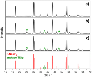
We synthesized NaYF4:Yb,Tm particles and combined them with a semiconductor by either directly synthesizing the titania shell (UCPs@TiO2) or by mixing them with commercial TiO2 (P25, Evonik) (UCPs + P25). The obtained UCPs crystals are in the form of microrods with an average length of approximately 1.5 μm and a diameter of roughly 0.3 μm (Fig. 1a). The surface of pure UCPs appears to be smooth, and the crystals are well-developed. The mixture of the UCPs and P25 is inhomogeneous on a microscale and shows two fractions – tiny TiO2 crystals and NaYF4:Yb3+,Tm3+ microrods (Fig. 1b). Deposition of TiO2 on the pure UCPs crystals by solvothermal method followed by the calcination resulted in the formation of a uniform layer of anatase TiO2 nanoparticles (sample β-NaYF4:Yb3+,Tm3+@TiO2, Fig. 1c), which was confirmed by the XRD and EDX analysis (Fig. 2 and S1c,† respectively).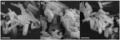 | ||
| Fig. 1 SEM images of (a) uncoated UCPs, (b) UCPs mixed with P25 and (c) UCPs coated with TiO2 layer. The scale bar represents 1 μm. | ||
The diffractogram of the β-NaYF4:Yb3+,Tm3+ sample represents very sharp diffraction peaks assigned to hexagonal crystalline structure (β-NaYF4, PDF no. 00-064-0156), indicating the excellent crystallinity of the synthesized material. No impurities from the cubic phase (α-NaYF4:Yb3+,Tm3+) crystals were detected. The size and crystalline structure of upconverting microcrystals combined with TiO2 were neither affected by the solvothermal synthesis of TiO2 nor the calcination process (Fig. 2).
Spectroscopic analysis
NaYF4 doped with Yb3+ and Tm3+ ions emits light within UV and visible range under a 980 nm laser excitation, as shown in Fig. 3a. The UV emission peaks with maxima at 349 and 362 nm, which are crucial for the NIR-driven photocatalytic activity of TiO2, are attributed to the five- and four-photon transitions of Tm3+ ions: 1I6 → 3F4, and 1D2 → 3H6, respectively. The two blue emission peaks centered at 450 and 474 nm correspond to the four- and three-photon 1D2 → 3F4 and 1G4 → 3H6 transitions of Tm3+ ions, respectively. The measurements of luminescence were performed for the materials in the form of thin films (f; cf. caption to Fig. 3) spread on ITO foil. Some significant spectral differences can be observed between the UCPs samples coated or mixed with titania and pure UCPs. The intensities of the emission bands in the UV range decrease for both UCPs@TiO2(f) and UCPs + P25(f), while the emission intensity of the band centered at 476 nm remains almost unaffected compared with the pure UCPs. The observed attenuation of the UV emission has arisen from the absorption of the light emitted by upconverting crystals by the TiO2, which was indicated by the DRS spectra of the UCPs samples (Fig. 3b). However, the reduction of the UV emission is more pronounced in the case of UCPs + P25(f) than for UCPs@TiO2(f), which may result from a weaker absorption of the UV light by the deposited TiO2. Moreover, the intensity of the 452 nm emission band with respect to the 476 nm band, which indicates the efficiency of four-photon transition, is significantly lower for UCPs@TiO2(f) than for UCPs + P25(f).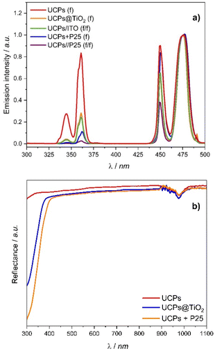 | ||
| Fig. 3 (a) Upconversion luminescence spectra of UCPs crystals (UCPs(f)), UCPs coated with titania (UCPs@TiO2(f)), UCPs mixed with P25 (UCPs + P25(f)), spatially separated UCPs and P25, deposited on two different ITO foil pieces (UCPs/P25(f/f)) and UCPs with additional uncoated ITO substrate (UCPs/ITO(f/f)). All spectra have been normalized to the emission intensity at 476 nm. (b) The DRS spectra of the UCPs, UCPs coated with titania layer (UCPs@TiO2), and UCPs mixed with P25 (UCPs + P25). The 980 nm band originates from the Yb3+ absorption. Tauc plots of UCPs@TiO2 and UCPs + P25 are presented in Fig. S2.† | ||
The efficiency of multi-photon processes strongly depends on the host's crystal field and geometry, concentration and spatial arrangement of the luminescent ions, particularly the presence of the volume and surface defects.23 The lower efficiency of upconversion arising from the four-photon transition observed for UCPs@TiO2 may result from the structural changes in UCPs particles caused by the TiO2 deposition process, which did not occur in the case of the UCPs + P25 physical mixture. A significant decrease in the UV emission intensity was also observed for the sample where UCPs and P25 films are spatially separated (UCPs/P25(f/f); cf. ESI†). Apart from the strong absorption of the UV light by P25, an additional reduction of visible light emission intensity was observed. In UCPs/P25(f/f) sample, incident light passes through the ITO foil covered with P25 before reaching the UCPs film. The attenuation of the visible light emission indicates partial absorption of the incident NIR light by ITO foil. It was confirmed by the decrease of intensities of all (349, 362, and 452 nm) peaks observed in the spectrum of UCPs thin film with the uncoated ITO foil placed in front of the sample (UCPs/ITO(f/f)).
Photoelectrochemical measurements
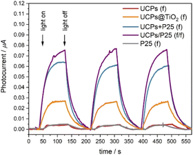
The same samples in the form of films were used in photoelectrochemical measurements to quantify the generation of electron–hole pairs in the UCPs-based photocatalytic systems under NIR light (Fig. 4). We observed repetitive photocurrent pulses from electrodes in response to laser pulses. The samples containing P25 (UCPs + P25(f) and UCPs/P25(f/f)) exhibit much stronger photocurrents than in the case of the UCPs@TiO2 sample, which indicates the advantage of mixed systems over coated ones. Although identical amounts of the UCPs and TiO2 were used for the preparation of UCPs + P25(f) and UCPs/P25(f/f) samples, the highest photocurrents were achieved for the sample where P25 was spatially separated from the UCPs layer. It is most likely because the electron transport through the electrode was not obstructed by the UCPs crystals dispersed in the semiconductor layer. Due to the spatial separation, the TiO2 layer was uniformly irradiated, and more semiconductor particles were in direct contact with the underlying ITO layer and electrolyte. The bare P25 and UCPs samples show scarcely any photo-response under NIR irradiation.Photocatalytic performance
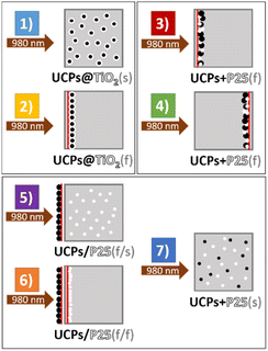
It has been reported that NaYF4:Yb3+,Tm3+ crystals directly coated with titania act as a more efficient photocatalyst compared with their physical mixture with TiO2.24–26 However, most of the papers on the titania-coated upconversion-based photocatalysts present the results of the photocatalytic test of colloidal solutions/suspensions of those materials.25,27,28 In our work, the photoactivity of the NaYF4:Yb3+,Tm3+ combined with TiO2 in the forms of suspended powders (s) and thin films (f) has been studied in various arrangements (Fig. 5). To verify the photocatalytic activity of examined samples, terephthalic acid (TA) was used as a probe compound to estimate of HO˙ radicals generation efficiency. TA reacts with photogenerated radicals to form a luminescent hydroxyterephthalic acid (TAOH).Fig. 6 shows the time dependence of the concentration of the generated TAOH upon NIR irradiation. Firstly, the results demonstrate that the materials in the form of thin films exhibit remarkably higher photocatalytic activity under NIR irradiation than their suspended counterparts. Irradiation of the UCPs@TiO2(s) (setup 1) generated an insignificant amount of hydroxyl radicals. However, the measured photocatalytic activity increased significantly when the same amount of the material was irradiated as a thin film (setup 2). It is most likely due to the substantial reduction of the solvent-based radiation losses in the thin film system. The intensity of the upconversion (IUC) emission strongly depends on the intensity of the excitation light (I), according to eqn (1):1
| IUC = k·In | (1) |
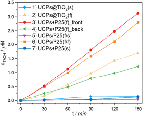 | ||
| Fig. 6 The concentration of TAOH generated in the presence of studied materials in the experimental setups depicted in Fig. 5 (1–7), under 980 nm irradiation. | ||
The obtained results not only demonstrate the superiority of the films of physical mixtures of UCPs/photocatalyst over the films of hybrid materials obtained in a multi-step process but also unequivocally show no need for direct contact between the UCPs and the photocatalyst. The high photocatalytic activity of setup 6, when the photocatalyst and UCPs layers are separated physically by a quartz wall of the cuvette, proves that the mechanism of TiO2 excitation involves the emission of UV light by UCPs and its absorption by titania particles (both confirmed by spectroscopic measurements). No other energy or electron transfer processes can occur through a thick (ca. 1.25 mm) quartz window. This shows that in the case of such hybrid semiconductor/UCPs materials, the heterojunction created between the components is irrelevant to overall activity because no electron transfer between them is necessary. In addition, in such systems with spatially separated components, it is possible to use various photocatalysts with the same film of UCPs and change them when necessary. Such design allows for the creation of interchangeable and reusable NIR-driven photocatalytic systems.
Experimental
Materials
Ytterbium chloride hexahydrate (YbCl3·6H2O, 99.99%, Sigma-Aldrich), yttrium chloride hexahydrate (YCl3·6H2O, 99.99%, Sigma-Aldrich), thulium chloride anhydrous (TmCl3, 99.99%, Sigma-Aldrich), sodium hydroxide (NaOH, 99.8%, POCh), oleic acid (OA, 99.9%, Fluka), ammonium fluoride (NH4F, Acros), ethyl alcohol (EtOH, POCh), cyclohexane (Sigma-Aldrich), hydrochloric acid (HCl, POCh), terephthalic acid (TA, Aldrich), and titanium(IV) oxide (P25, Evonik), titanium(IV) fluoride (TiF4, Sigma-Aldrich), polyvinylpyrrolidone (PVP10, Sigma-Aldrich), barium sulfate (BaSO4, Sigma-Aldrich) were used as received without further purification.Synthesis of NaYF4:Yb3+,Tm3+ microcrystals (UCPs)
The NaYF4:Yb,Tm phosphors were prepared by a solvothermal method. In a typical process, 0.36 g NaOH was transferred to a Teflon autoclave lining, filled with 2.4 ml ethanol and 0.6 ml distilled water, and stirred until a homogeneous solution was obtained. Vigorous stirring was continued throughout the preparation of the reaction mixture. Then 6 ml of oleic acid was added to the solution. After 20 minutes, a total volume of 1.5 ml of 0.2 M rare-earth chlorides solutions (YCl3, YbCl3, and TmCl3 with a stoichiometric ratio of 50![[thin space (1/6-em)]](https://www.rsc.org/images/entities/char_2009.gif) :
:![[thin space (1/6-em)]](https://www.rsc.org/images/entities/char_2009.gif) 49
49![[thin space (1/6-em)]](https://www.rsc.org/images/entities/char_2009.gif) :
:![[thin space (1/6-em)]](https://www.rsc.org/images/entities/char_2009.gif) 1) was added dropwise to the reaction vessel. The amount of the added 0.1 M NH4F was fixed at 2.4 ml for obtaining particles with F−/RE3+ = 8/1 molar ratio.
1) was added dropwise to the reaction vessel. The amount of the added 0.1 M NH4F was fixed at 2.4 ml for obtaining particles with F−/RE3+ = 8/1 molar ratio.
The Teflon lining with the resulting solution was then placed in a stainless steel autoclave, sealed, and maintained at 190 °C for 12 hours. The synthesized particles were washed with ethanol and centrifuged at 5000 rpm for 20 minutes. The supernatant was removed, and the particles were washed several times with cyclohexane and ethanol to remove the remaining unbound oleic acid and possible impurities formed during the synthesis. The purified oleate-capped particles were collected and dried in the oven at 60 °C. To remove oleic acid from the surface of NaYF4:Yb3+,Tm3+ crystals to obtain ligand-free water-dispersible upconverting microcrystals, the modified literature procedure reported by Bogdan et al. was used.33 In a typical experiment, oleate-capped particles were dispersed in 2 ml of 2 M HCl solution and sonicated for 15 min to remove surface ligands. The products were washed with ethanol and water three times, collected by centrifugation, and dried in the oven at 60 °C. To improve the crystallinity of the materials and remove any organic impurities, the obtained powders were calcined in the oven at 400 °C for 3 hours.
Synthesis of NaYF4:Yb3+,Tm3+@TiO2 composites (UCPs@TiO2)
The NaYF4:Yb3+,Tm3+@TiO2 composites were synthesized according to a modified literature procedure.34 In a typical experiment, 25 mg of the previously synthesized upconverting particles were mixed with 3 ml of deionized water and 0.3 g of PVP. The mixture was sonicated until all of the PVP was dissolved. Subsequently, 10 ml of ethanol was added to a reaction flask, and the content was stirred for 30 minutes. As a titanium source, 4 ml 0.025 M TiF4 solution was added dropwise. The reaction content was transferred into a 20 ml Teflon-lined steel autoclave and maintained at 180 °C for 6 h. After cooling to room temperature, the obtained products were precipitated with ethanol, centrifuged at 3300g for 10 minutes, and washed with DI water and ethanol three times. The particles were then dried on air and further calcined in the oven at 400 °C for 3 hours.Preparation of the thin films of the materials
The mixture of the UCPs and P25 (UCP + P25) was prepared by grinding in a mortar 2 mg of the UCPs with 1 mg of P25. Then, 20 μl of water was added, and the suspension was transferred on the ITO foil and spread evenly to form a uniform layer of the area matching the beam size (vide infra). The film was then dried in a stream of warm air (ca. 40–50 °C). To prepare a sample composed of spatially separated UCPs and TiO2 (P25), labelled UCPs/P25, 2 mg of UCPs and 1 mg of P25 were ground and loaded onto separate ITO foil sheets and then dried. The thin film of UCPs coated with titania (UCPs@TiO2) was prepared correspondingly, with 3 mg of the material loaded onto the ITO foil.Characterization
The purity and phase structure of the synthesized particles were obtained using a MiniFlex 600 (Rigaku) X-ray diffractometer equipped with CuKα nickel-filtered source lamp (λ = 1.54 Å) operating at 40 kV voltage. The scan range was 3–70° 2θ with a step of 0.02° and a speed of 10° per minute.The size, morphology, and elemental analyses were determined using a Vega 3 LM (Tescan) scanning electron microscope equipped with a LaB6 cathode and EDS detector (10 mm2 x-act SDD detector, Oxford Instruments) operating at 20 and 30 kV voltage. The samples were prepared by spreading the powders on carbon tape.
PerkinElmer LS55 fluorescence spectrometer was used to record luminescence spectra of hydroxyterephthalic acid. The excitation wavelength was set to 315 nm, and emission was measured in the 300–600 nm range. The measurements were performed in high-purity cuvettes with a path length of 1 cm.
The diffuse reflectance spectra (DRS) were measured in a Shimadzu UV-3600 spectrophotometer equipped with a 5 cm diameter integrating sphere. The samples were ground in the agate mortar with barium sulfate in the weight ratio of 1![[thin space (1/6-em)]](https://www.rsc.org/images/entities/char_2009.gif) :
:![[thin space (1/6-em)]](https://www.rsc.org/images/entities/char_2009.gif) 50. BaSO4 was also used as a reference.
50. BaSO4 was also used as a reference.
The upconversion luminescence spectra of the thin film samples were obtained using a 980 CW diode laser (LambdaWave) with a light power of 0.84 W and an irradiated area of 8 mm2 (light power density: 105 mW mm−2) combined with SPEX Fluorolog 3.22 (Horiba) spectrofluorometer. The film samples were prepared using the same procedure as for the preparation of thin films for photocatalytic tests (see: Photocatalytic measurements: a part).
Photoelectrochemical measurements were performed using 0.1 mol per dm3 KNO3 water solution as an electrolyte in a three-electrode set-up. The working electrode was prepared by spreading an aqueous suspension of studied material on a transparent foil covered with indium–tin-oxide (ITO) and dried afterwards in a stream of warm air (ca. 40–50 °C). The silver chloride electrode and a platinum wire were used as reference and auxiliary electrodes, respectively. The measurements were carried out using a 980 nm laser diode with an output power of 0.84 W and the photoelectric spectrometer and potentiostat (Instytut Fotonowy).
Photocatalytic measurements
Terephthalic acid (TA) was used as a reagent to investigate the photocatalytic activity of the materials. The fluorescence intensity (at λmax = 426 nm) of hydroxyterephthalic acid (TAOH) formed in the reaction of TA hydroxylation was measured. We studied the photocatalytic activity of several samples in the form of suspended powders and thin films in various arrangements, and the following abbreviations for the prepared samples were used:– UCPs@TiO2(s) – suspension of NaYF4:Yb3+,Tm3+ crystals coated with solvothermally synthesized titania;
– UCPs@TiO2(f) – a thin film of NaYF4:Yb3+,Tm3+ crystals coated with solvothermally synthesized titania;
– UCPs + P25(f) – a thin film of NaYF4:Yb3+,Tm3+ crystals mixed with commercially available titania – P25 (Evonik);
– UCPs/P25(f/s) – thin film of NaYF4:Yb3+,Tm3+ crystals and suspension of P25;
– UCPs/P25(f/f) – thin film of NaYF4:Yb3+,Tm3+ crystals with an adjacent thin film of P25;
– UCPs + P25(s) – suspension of a mixture of NaYF4:Yb3+,Tm3+ crystals, and P25.
Photocatalytic tests performed for thin films
Typically, 1.5 ml of the 0.3 mM TA solution in 10 mM NaOH aqueous solution was added to the glass cuvette. The UCPs + P25(f) sample was prepared by mixing 2 mg of the UCPs and 1 mg of P25 in a mortar and loaded on a thin transparent ITO foil. For the UCPs@TiO2(f) sample, 3 mg of the material was used for one sample. The prepared film was then immersed in the TA solution and irradiated with a 0.84 W 980 nm laser diode. The cuvette was air-cooled, so the temperature rise of the suspension did not exceed 50 °C. In the experiment with the two separated thin films (UCPs/P25(f/f)), 2 mg of UCPs and 1 mg of P25 were used for the preparation of the films, respectively. The film with P25 was then immersed in the TA solution and the film with UCPs was placed in front of a cuvette. The whole setup was irradiated with a 0.84 W 980 nm laser diode. To determine the amount of generated TAOH, proportional to the amount of generated HO˙ radicals, the fluorescence of the generated TAOH was measured every 30 minutes.Photocatalytic tests performed on suspensions
The experiments with suspensions were conducted in the same conditions as for the thin films. Materials were suspended in 1.5 ml of the 0.3 mM TA solution in 10 mM NaOH aqueous solution and irradiated with the 980 nm laser diode. For the UCPs@TiO2(s), 3 mg of the material was used. In the case of a UCPs/P25(f/s) sample, 1 mg of P25 was suspended in a solution, while 2 mg of UCPs was loaded on a transparent ITO foil in the form of a thin film, which was then placed in front of a cuvette. For a UCPs + P25(s) sample, 1 mg of P25 and 2 mg of UCPs were suspended in the same solution. Five identical samples were prepared and irradiated for 30, 60, 90, 120 and 150 minutes for each material. After that, the suspensions were collected and centrifuged to remove the photocatalyst and UCPs, and then the emission spectrum of the supernatant was measured.Conclusions
We synthesized well-defined hexagonal NaYF4:Yb3+,Tm3+ microcrystals (UCPs) exhibiting upconverting properties. Upon 980 nm irradiation, they emit intense UV and visible light, making them perfect candidates for use in NIR-driven photocatalysis. We combined UCPs with a photocatalyst by coating titania directly on their surface in the hydrothermal process and by preparing a physical mixture with commercially available TiO2 (P25, Evonik). The obtained materials were characterized by SEM, EDX, XRD and photoluminescence spectroscopy. We studied the photocatalytic and photoelectrochemical activity of such UCPs-based photocatalytic systems in various experimental setups. We have discovered that the most efficient way to increase the photocatalytic activity of the studied materials is to prepare them in the form of thin films. An additional advantage of the proposed approach is the possibility of using microcrystalline UCPs, which are relatively easy to prepare and more efficient in NIR upconversion compared to their nanocrystalline analogues. We also proved that TiO2 can be excited by the upconverted light without any direct physical contact between the photocatalyst and the upconverter, as demonstrated by the samples where a cuvette wall spatially separates the photocatalyst and UCPs. Such design allows for the creation of interchangeable and reusable NIR-driven photocatalytic systems.Data availability
The data supporting this article have been included as part of the ESI.†Author contributions
Paulina O'Callaghan: investigation, validation, visualization, writing – original draft; Agnieszka Jarosz-Duda: investigation, validation, visualization, writing – original draft; Joanna Kuncewicz: methodology, investigation, writing – original draft, writing – review and editing; Krzysztof Dzierżęga: investigation, validation; Wojciech Macyk: funding acquisition, project administration, methodology, writing – review and editing.Conflicts of interest
There are no conflicts to declare.Acknowledgements
This research was financially supported by the Foundation for Polish Science within the TEAM project (POIR.04.04.00-00-3D74/16).References
- L. Wang, X. Xu, Q. Cheng, S. X. Dou and Y. Du, Small, 2019, 1904107 Search PubMed.
- W. Wei, M. Ding, C. Lu, Y. Ni and Z. Xu, Appl. Catal., B, 2014, 144, 379–385 CrossRef.
- W. Shijia, J. Lv, F. Wang, N. Duan, Q. Li and Z. Wang, Sci. Rep., 2017, 7, 1–11 CrossRef PubMed.
- S. M. Zheng, L. Li, K. Wang, R. Qiao, Y. Zhong, Y. Hu and Z. Li, J. Mater. Chem. A, 2014, 2, 13486–13491 RSC.
- W. Wanni, M. Zhao, C. Zhang and H. Qian, Chem. Rec., 2020, 20, 2–9 CrossRef PubMed.
- X. Liu, C.-H. Yan and J. A. Capobianco, Chem. Soc. Rev., 2015, 44, 1299–1301 RSC.
- Y. Sang, H. Liu and A. Umar, ChemCatChem, 2015, 7, 559–573 CrossRef CAS.
- Y. Wu, S. Y. Chan, J. Xu and X. Liu, Chem.–Asian J., 2021, 16, 2596–2609 CrossRef CAS PubMed.
- C. Li, F. Wang, J. Zhu and C. Y. Jimmy, Appl. Catal., B, 2010, 100, 433–439 CrossRef CAS.
- Q. Zhang, F. Yang, Z. Xu, M. Chaker and D. Ma, Nanoscale Horiz., 2019, 4, 579–591 RSC.
- W. Yang, X. Li, D. Chi, H. Zhang and X. Liu, Nanotechnology, 2014, 25, 482001 CrossRef PubMed.
- A. Kar, S. Kundu and A. Patra, ChemPhysChem, 2015, 16, 505–521 CrossRef CAS PubMed.
- D. Yin, L. Zhang, X. Cao, Z. Chen and J. Tang, Dalton Trans., 2016, 45, 1467–1475 RSC.
- A. Jarosz-Duda, P. O'Callaghan, J. Kuncewicz, P. Łabuz and W. Macyk, Catalysts, 2020, 10, 232 CrossRef CAS.
- A. A. Chilkalwar and S. S. Rayalu, J. Phys. Chem. C, 2018, 122, 26307–26314 CrossRef CAS.
- H. Huang, H. Li, Z. Wang, P. Wang and Z. Zheng, Chem. Eng. J., 2019, 361, 1089–1097 CrossRef CAS.
- Z. Xu, M. Quintanilla, F. Vetrone, A. O. Govorov, M. Chaker and D. Ma, Adv. Funct. Mater., 2015, 25, 2950–2960 CrossRef CAS.
- Y. Yang, P. Zhou, W. Xu, S. Xu, Y. Jiang, X. Chen and H. Song, J. Mater. Chem. C, 2016, 4, 659–662 RSC.
- X. Xu, Y. Sun, Q. Zhang, H. Cai, Q. Li and S. Zhou, Opt. Mater., 2019, 94, 444–453 CrossRef CAS.
- H. Anwer and J.-W. Park, Appl. Catal., B, 2019, 243, 438–447 CrossRef CAS.
- Q. Zhang, F. Yang, Z. Xu, M. Chaker and D. Ma, Nanoscale Horiz., 2019, 4, 579–591 RSC.
- B. S. Richards, D. Hudry, D. Busko, A. Turshatov and I. A. Howard, Chem. Rev., 2021, 121, 9165–9195 CrossRef CAS PubMed.
- X. Li, F. Zhang and D. Zhao, Nano Today, 2013, 8, 643–676 CrossRef CAS.
- Y. Tang, W. Di, X. Zhai, R. Yang and W. Qin, ACS Catal., 2013, 3, 405–412 CrossRef CAS.
- W. Wang, Y. Li, Z. Kang, F. Wang and J. C. Yu, Appl. Catal., B, 2016, 182, 184–192 CrossRef CAS.
- Y. Chen, S. Mishra, G. Ledoux, E. Jeanneau, M. Daniel, J. Zhang and S. Daniele, Chem.–Asian J., 2014, 9, 2415–2421 CrossRef CAS PubMed.
- D.-X. Xu, Z.-W. Lian, M.-I. Fu, B. Yuan, J.-W. Shi and H.-J. Cui, Appl. Catal., B, 2013, 142–143, 377–386 CrossRef CAS.
- W. Wang, W. Huang, Y. Ni, C. Lu and Z. Xu, ACS Appl. Mater. Interfaces, 2014, 6, 340–348 CrossRef CAS PubMed.
- T.-M. Liu, J. Conde, T. Lipiński, A. Bednarkiewicz and C.-C. Huang, NPG Asia Mater., 2016, 8, e295 CrossRef CAS.
- F. Wang, J. Wang and X. Liu, Angew. Chem., Int. Ed., 2010, 49, 7456–7460 CrossRef CAS PubMed.
- F. T. Rabouw, P. T. Prins, P. Villanueva-Delgado, M. Castelijns, R. G. Geitenbeek and A. Meijerink, ACS Nano, 2018, 12, 4812–4823 CrossRef CAS PubMed.
- D. C. Hurum, A. G. Agrios, K. A. Gray, T. Rajh and M. C. Thurnaueret, J. Phys. Chem. B, 2003, 107, 4545–4549 CrossRef CAS.
- N. Bogdan, F. Vetrone, G. A. Ozin and J. A. Capobianco, Nano Lett., 2011, 11, 835–840 CrossRef CAS PubMed.
- Z. Hou, Y. Zhang, K. Deng, Y. Chen, X. Li, X. Deng, Z. Cheng, H. Lian, C. Li and J. Lin, ACS Nano, 2015, 9, 2584–2599 CrossRef CAS PubMed.
Footnote |
| † Electronic supplementary information (ESI) available. See DOI: https://doi.org/10.1039/d4ra04185b |
| This journal is © The Royal Society of Chemistry 2024 |

